1982 VOLVO 700 torque
[x] Cancel search: torquePage 154 of 168
70019401960 Specifications
Section
4 Power Transmission
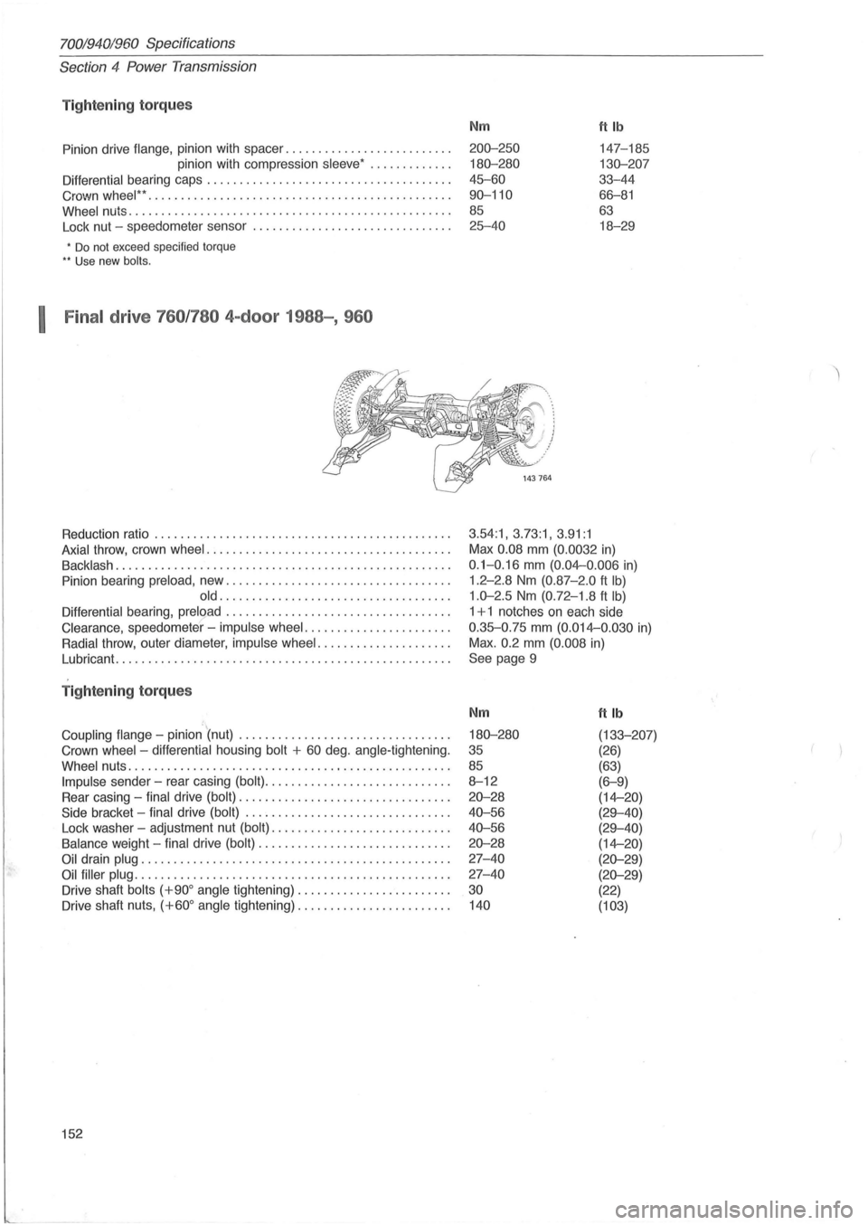
Tightening torqu es
Pinion drive flange, pinion with spacer .......... ........ ....... .
pinion with compression
sleeve ' ............ .
Differential bearing caps .............................. ...... . .
Crown
wheel " .. ............................ .......... ...... .
Wheel nuts ...... ............................... .. .......... .
Lock nut -speedometer sensor .
............................. .
• Do not exceed specified torque .. Use new bolts.
I Final drive 760 /780 4-door 1988-, 960
Reduction ratio ................................... .......... .
Axial throw , crown wheel ..................................... .
Backlash ............... .................................... .
Pinion bearing
preload , new .................................. .
old ........ .. ..... .................... .
Differential bearing, preload .................................. .
Clearance , speedometer' -impulse wheel ....... ............... .
Radial throw , outer diameter, impulse wheel ....... ............. .
Lubricant.
..... ............................................. .
T ightening torque s
='.. Coupling flange -pinion (nut) ................................ .
Crown
wheel -differential housing bolt + 60 deg . angle-tightening.
Wheel nuts .. ............................. .................. .
Impulse sender -rear casing (bolt) ............................ .
Rear casing -
final drive (bolt) ................................ .
Side bracket -final drive (bolt) ............................... .
Lock washer -adjustment nut
(bolt) ........................... .
Balance weight -final drive (bolt) ............................. .
Oil drain plug ............................................... .
Oil filler plug ................................................ .
Drive shaft
bolts (+900 angle tightening) ....................... .
Drive shaft nuts,
(+600 angle tightening) ............... ........ .
152
Nm ttlb
200-250 147-185
180-280 130-207
45-60 33-44
90-110 66-81
85 63
25-40 18-29
3.54:1, 3.73:1, 3.91:1
Max 0.08 mm (0.0032 in)
0.1-0. 16 mm (0.04--0 .006 in)
1.2-2.8 Nm (0.87 -2.0 ft Ib)
1.0-2.5 Nm (0.72-1 .8 ft Ib)
1 + 1 notches on each side
0.35-0.75 mm (0.014--0.030 in)
Max.
0.2 mm (0. 008 in)
See page 9
Nm
180-280
35
85
8-12
20-28
40-56
40-56
20-28
27-40
27-40
30
140
ftlb
(133-207)
(26)
(63)
(6-9)
(14--20)
(29-40)
(29-40)
(14--20)
(20-29)
(20-29)
(22)
(103)
Page 155 of 168
70019401960 Specifications
Section
5 Brakes
Section 5 Brakes
fJy ~~
132426
B rake fluid
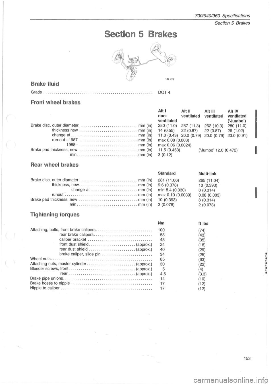
Grade................................... .... ... ............ DOT 4
Fron t wheel brakes
(
Brake disc, outer diameter, .. .................... .. .... mm (in)
thickness new
............................ . mm (in)
change at
........ ........... .............. mm (in)
Alt I Alt" Alt III Alt IV
! non -
ve ntil ated
ve ntilat ed ventilated
ventil ated
('Jumbo')
I
280 (11.0) 287 (11.3) 262 (10.3) 280 (11.0)
14 (0.55)
22 (0.87)
22 (0.87) 26 (1.02)
11.0 (0.43) 20.0 (0.79) 20 .0 (0. 79) 23.0 (0.91)
run-out -1987 ... ....... .. ................. mm (in)
max 0.08 (0.003)
1988-.................. ........... mm (in)
Brake pad thickness, new .
............................ mm (in)
min
.... ............ ........... ... mm (in) max
0
.06 (0.0024)
I 11.5 (0.453)
('Jumbo' 12.0 (0.472)
3
(0. 12)
Rear wheel brakes
Sta ndard Multi -link
Brake disc, outer diameter ....... ...................... mm (in) 281 (11.06)
265 (11.04)
thickness, new ............................. mm (in)
change at
............... ........ mm (in)
runout .
...................... ............. mm (in)
Brake pad thickness , new .
..... ....... ............... . mm (in) 9
.6 (0.378)
10 (0.393)
I
min 8.4 (0.330) 8 (0.314)
max
0.10 (0.0039)
0.08 (0.003)
10
(0. 393)
8 (0.314)
min ............ .................. mm (in)
2 (0.078) 2 (0.078)
T ight enin g torque s
Nm ftlbs
Attaching , bolts , front brake calipers ........................... . 100 (74)
rear brake calipers ............................ .
58 (43)
caliper bracket ....................... ....... . .
48 (35)
front dust
shield .................... ... (approx .)
24 (18)
rear dust
shield ................ ....... (approx.)
brake
caliper, slide pin ................... ..... .
40 (29)
"I 34
(25) II Wheel nuts ................................................. .
85 (63) II II Attaching nuts, master cylinder ..... ................... (approx.) 30 (22) II II Bleeder screws, front ......................... ........ (approx .)
5 (4) II ·11 rear ...... .......... ................. (approx .)
4.5 (3.3) II
Brake pipe unions ...... .......... ............ ............... .
14 (10) Brake hoses to nipple ....................................... .
17 (12)
Nipple to caliper ......... ................................... .
17 (12)
153
Page 158 of 168
70019401960 Specifications
Section
6 Suspension and steering
A
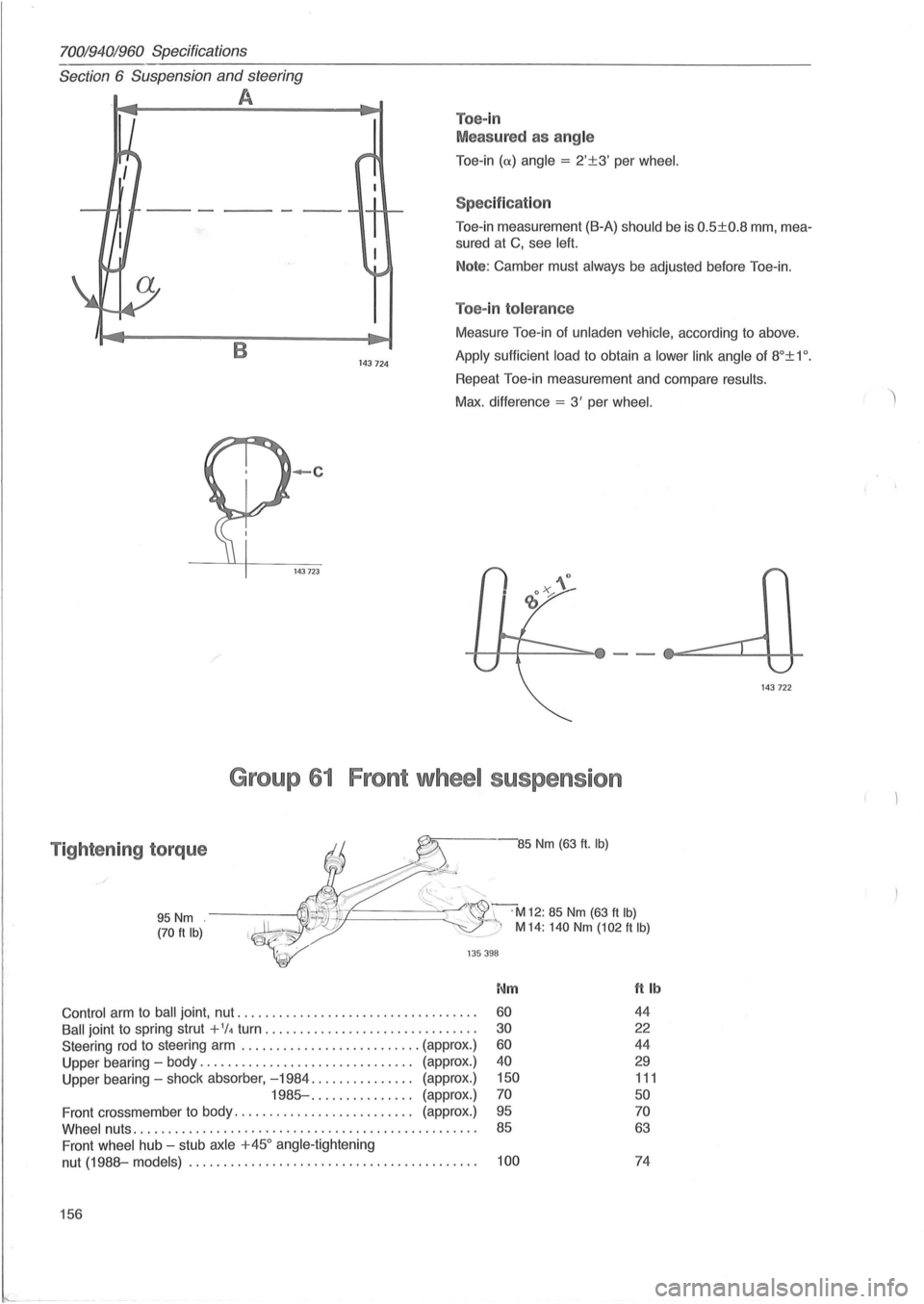
Toe-in
Meas ured as ang le
Toe -in (
Toe-in measurement (B-A) should be is 0.5±0.8 mm, mea
sured at C, see left.
Note: Camber must always be adjusted before Toe-in.
Toe-in tolerance
B 143 724
Measure Toe-in of unladen vehicle, according to above .
Apply sufficient load to obtain a lower link angle of 8°± 1 o .
Repeat Toe-in measurement and compare results.
Max. difference = 3' per wheel.
-c
143723
Group 61 Front wheel suspension
Tightening torque -85 Nm (63 ft. Ib)
95 Nm (70 ft Ib)
~~-.'"
~~======~~C r~M12: 85 Nm (63 ft Ib) ~:./ M 14: 140 Nm (102 ft Ib)
135 398
Nm ft Ib
Control arm to ball joint , nut .................................. . 60 44
Ball joint to spring strut + 1/4 turn .............. ................ . 30 22
Steering rod to steering arm .......................... (approx.) 60 44
Upper bearing -body ............................... (approx.) 40 29
Upper bearing -shock absorber, -1984 ............... (approx .) 150 111
1985- .... ........... (approx.) 70 50
Front crossmember to body. . . . . . . . . . . . . . . . . . . . . . . . . . (approx.) 95 70
Whee l nuts ......... .. ................................ .. ... . . 85 63
Front wheel hub -stub axle +450 angle -tightening
nut
(1988-models) ................................. . ....... . 100 74
156
143 722
Page 159 of 168
(
70019401960 Specifications
Section 6 Suspension and steering
Group 64 Steering
Steeri ng gear
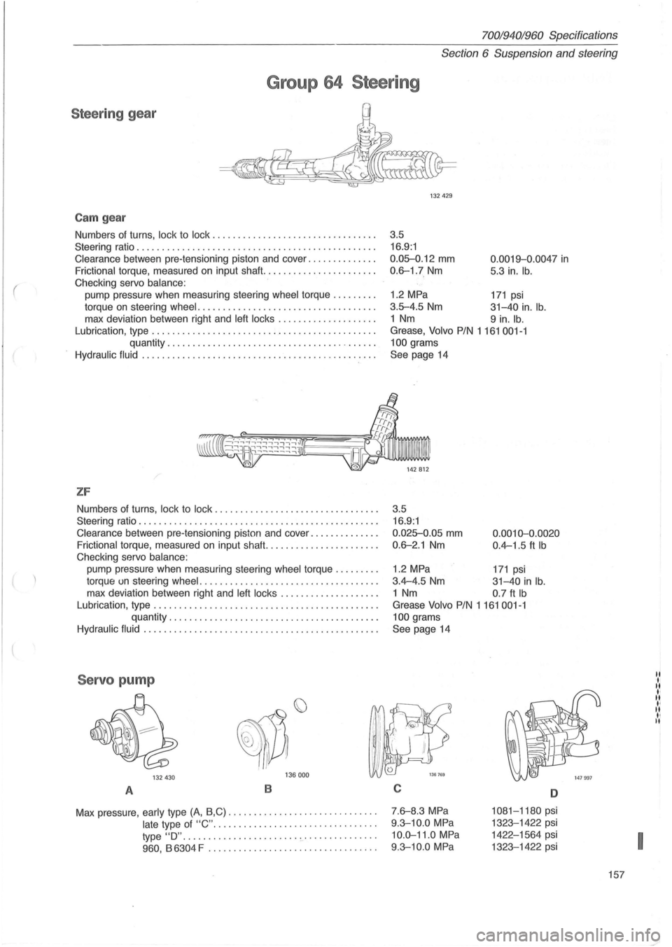
Cam gear
Numbers of turns, lock to lock ...................... .......... .
Steering ratio .
.............................................. .
Clearance between pre-tensioning piston and cover ............. .
Frictional torque, measured on input shaft ...................... .
Checking servo
balance:
pump pressure when measuring steering wheel torque ........ .
torque
on steering wheel . ............................. ..... .
max deviation between right and
left locks ................... .
Lubrication, type
............................................ .
quantity .
........................................ .
Hydraulic fluid ..... .... ..................................... .
/
ZF
Numbers of turns, lock to lock ................................ .
Steering ratio
............................................... .
Clearance between pre-tensioning piston and cover ............. .
Frictional torque, measured on input shafl. ..................... .
Checking servo
balance:
pump pressure when measuring steering wheel torque ........ .
torque un steering
wheel ................................... .
max deviation between right and
left locks ................... .
Lubrication, type
............................................ .
quantity
........................... .............. .
Hydraulic fluid .............................................. .
Servo pump
132 430 136 000
A B
Max
pressure, early type (A, B,C) ............................ . .
late type of "C" ....... .... ..................... .
type
"0" ................... .... 0-' .•• •••••.••...
960 , B 6304 F ................................. .
132429
3 .5
16.9:1
0.0~.12 mm
0.6-1.7 Nm
0 .0019-0.0047 in
5.3 in. lb.
1.2 MPa 171 psi
3 .5-4.5 Nm 31-40 in. lb.
1 Nm 9 in. lb.
Grease, Volvo PIN 1161001-1
100
grams
See page 14
3.5 16.9:1
0.025-0.05 mm
0.6-2.1 Nm
0.0010-0.0020
0.4-1.5 ft Ib
1.2 MPa 171 psi
3.4-4.5 Nm 31-40 in lb .
1 Nm 0.7 ft Ib
Grease Volvo PIN 1 161 001-1
100
grams
See page 14
C
7 .6-8.3 MPa
9 .3-10.0 MPa
10 .0-11.0 MPa
9.3-10.0 MPa
D
1081-1180 psi
1323-1422 psi
1422-1564 psi
1323-1422 psi
157
I
Page 160 of 168
70019401960 Specificatidns
Section
6 Rear wheel suspension
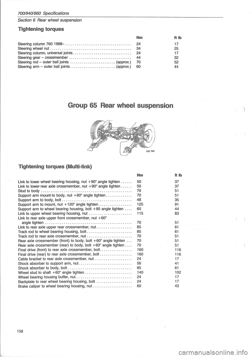
Tightening torques
Nm ftlb
Steering column 760 1988-............................. .. ... .
24 17
Steering wheel nut .
........ ................................. . 34
25
Steering column, universal joints
.............................. .
24 17
Steering gear -
cr
44 32
Steering
rod - outer ' ball joints ........................ (approx .) 70 52
Steering arm -outer
ball joints ........................ (approx.) 60 44
Group 65 Rear wheel suspens ion
Tightening torques (Multi-link)
Nm ft Ib
Link to lower , wheel beBring housing, nut +900~ngle tighten ..... . 50 37
Link to
lowen'rear axle crossmember, nut +900 angle tighten ..... . 50 37
Stud to body ................................................ .. . 70 51
Support arm mount lto body, nut +900 angle tighten ............. . 70 51
Support arm to body, bolt .................................... . 48 35
Support arm to mount, nut + 1200 angle
tighten ................. . 125 91
Support
arm to wheel bearing housing, bolt +90 angle tighten ... . 60 44
Link to upper wheel bearing housing, nut ...... ................ . 115 83
Link
to rear axle upper front crossmember, nut +600
angle tighten ............................................. . 70 51
Link to rear axle upper rear crossmember, nut .................. . 85 61
Track rod to wheel bearing housing, bolt ..................... .. . 85 61
Track rod to rear axle crossmember, nut ....................... . 70 51
Rear axle crossmember (front) to body, bolt +600 angle tighten .. . 70 51
Rear axle crossmember (rear) to body, bolt +600 angle tighten ... . 70 51
Final drive (front) to rear axle crossmember, bolt ................ . 160 116
Final drive (rear) to rear axle crossmember, bolt
................ . 160 116
Cable bracket to rear axle cross member, nut
................... . 24
17
Shock absorber to support arm, nut ........................... . 56 41
Shock absorber to body, bolt ................................. . 85 61
Wheel stud to shaft +600 angle tighten ........................ . 140 102
Wheel
bearing housing buffer, nut. ............................ . 24 17
Backplate to rear wheel bearing housing, bolt
.................. . 24
17
Brake caliper to wheel bearing housing, nut ..
.................. . 60 43
158
Page 161 of 168
(
700194019fiO Specifications
Section
7 Springs, dampers and wheels
Section 7 Springs, shock absorbers, wheels
Group 77 Wheels, tires, hubs
Wheels
RIMS Aluminium
Lateral runout (A) . . . . . . . . . . . . . . . . . . . . . . . . . . . . . . . . . . . . . . . . . . . . Max. 0.8 mm
(0.032 in)
Radial runout (8). . . . . . . . . . . . . . . . . . . . . . . . . . . . . . . . . . . . . . . . . . . . . Max. 0.6 mm
(0.024 in)
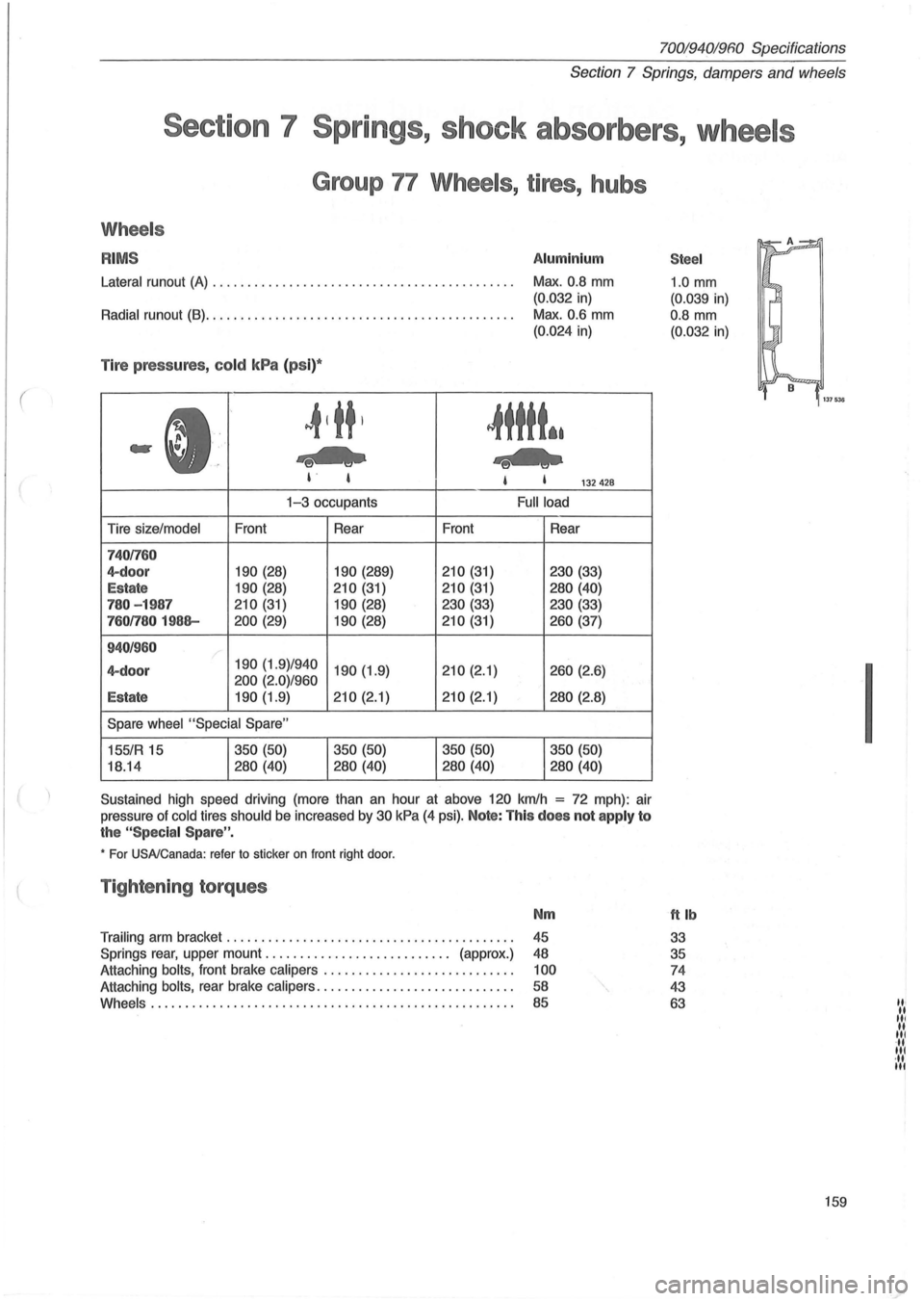
Tire pressures , cold kPa (ps i)*
~tttt*.
-e-US , I 132428
Tire size/model
7401760
4-door
Estate
780 - 1987
7601780 1988-
940/960
4-doo r
Estate
Front
190 (28)
190 (28)
210 (31)
200 (29)
1-3 occupants
Rear
190 (289)
210 (31)
190 (28)
190 (28)
190 (1.9)/940 190 (1.9)
200 (2.0)/960
190 (1.9) 210 (2.1)
Spare wheel "Special Spare"
155/R 15
18.14 350
(50)
280 (40) 350
(50)
280 (40) Front
210 (31)
210 (31)
230 (33)
210 (31)
210 (2.1)
210 (2.1)
350 (50)
280 (40)
Full load
Rear
230 (33)
280 (40)
230 (33)
260 (37)
260 (2.6)
280 (2.8)
350 (50)
280 (40)
Sustained high speed driving (more than an hour at above 120 kmlh
= 72 mph) : air
pressure of
cold tires should be increased by 30 kPa (4 psi). Note: This does not apply to
the "Spec ia l Spare " .
• For USA/Canada: refer to sticker on front right door.
Tightening torques
Nm
Trailing arm bracket ......................................... .
45
Springs
rear, upper mount. . . . . . . . . . . . . . . . . . . . . . . . . .. (approx.) 48
Attaching
bolts, front brake calipers ............. .............. . 100
Attaching bolts, rear brake calipers ............................ . 58
Whe e
ls .................................................... .
85
Stee l
1.0 mm
(0.039 in)
0.8
mm
(0.032 in)
ttlb
33
35
74
43
63
159
I
III .. III II III ... III ·11 III
Page 162 of 168
700/940/960 Specifications
Section 8 Body and interior
Section 8 Body and interior
Air condition ing
Refrigerant, type ............ ..................... ........... .
quantity .
........................................ .
7601988 ............ ......... ......... .. .
Compressor, make
+ designation .................... Delco R4
Freon 12 (dichlorodifluoromethane)
1.2 kg (2.6 Ib)
1 .1 kg (2.4lb)
Sanden
York A210 Kiki YA 15 Sanden
Sankyo
OKS 15BHI S0709
S0510
CH
max. rev ......................... . .... 115 rls 100 rls 100 rls 115 rls 100 rls
(7000 rIm) (6000 rIm) (6000 rIm) (7000 rIm) (6000 rIm)
lubricating oil capacity .................. 177 ml 135 ml 300 ml 200 ml 240 ml
safety valve, actuated at ................ 3.1 MPa 3.2 MPa 3.1 MPa
3.2 MPa 3
.2 MPa
(441 psi) (455 psi) (441 psi) (455 psi) (455 psi)
Lubricating
oil . .................................... Volvo PIN 1 160048-3
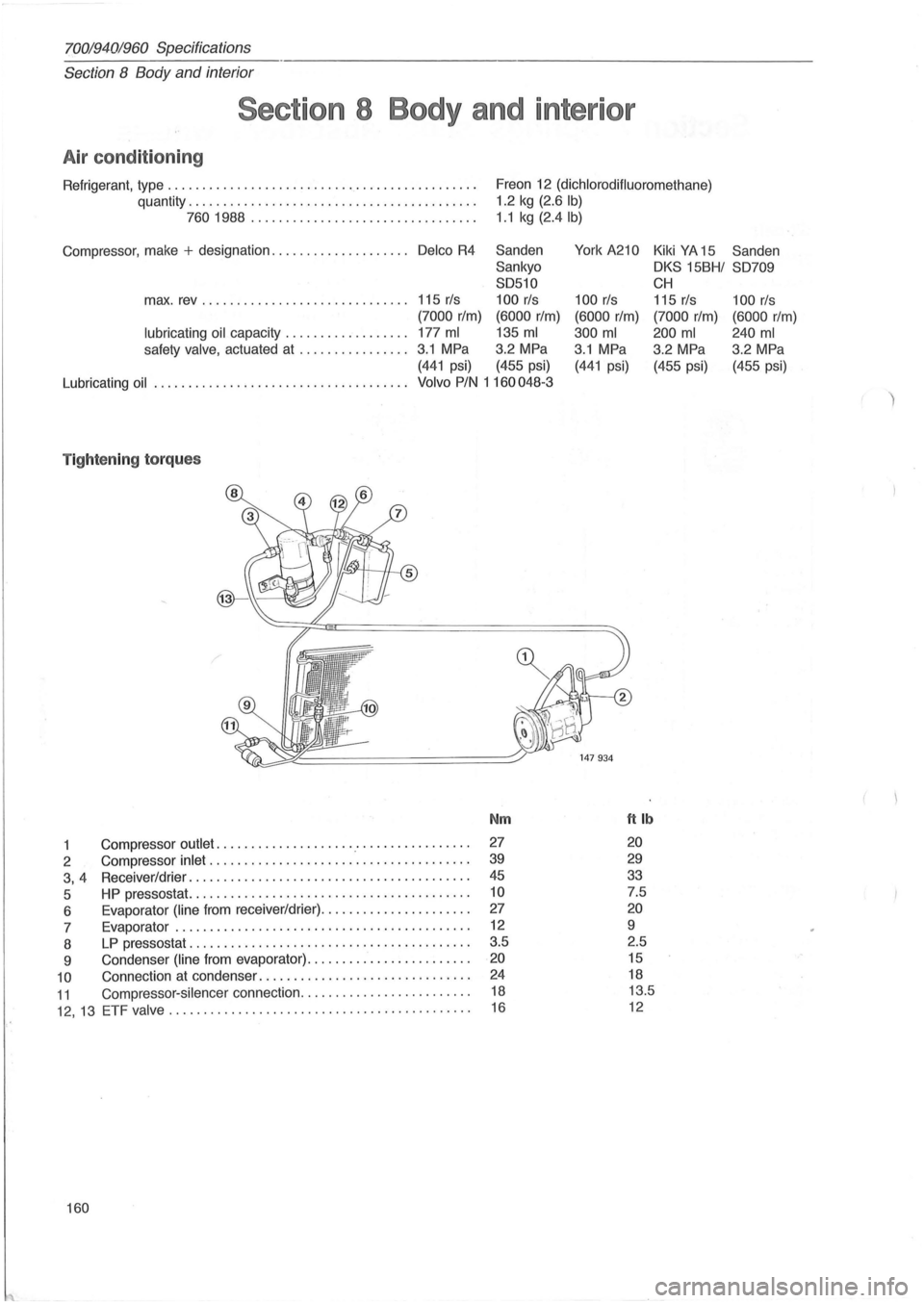
T ightening torques
Nm ftlb
1 Compressor outlet .................... .' ............... . 27 20
2 Compressor inlet ............................ ......... . 39 29
3, 4 Receiver/drier .............. .......................... . 45 33
5 HP pressostat. ....................................... . 10 7.5
6 Evaporator
(line from receiver/drier) ........... .... ...... . 27 20
7 Evaporator ............. .................... ......... . 12 9
8
LP pressostat ............. ........................ ... . 3.5
2.5
9 Condenser
(line from evaporator) ....................... . 20 15
10 Connection at condenser .............................. . 24 18
11 Compressor-silencer connection ........................ .
12, 13 ETF valve ......... .................................. .
18 13.5
16 12
160