1982 VOLVO 700 light
[x] Cancel search: lightPage 19 of 168
(
70019401960 Specifications
Section
2 B 19, B 23 Engines
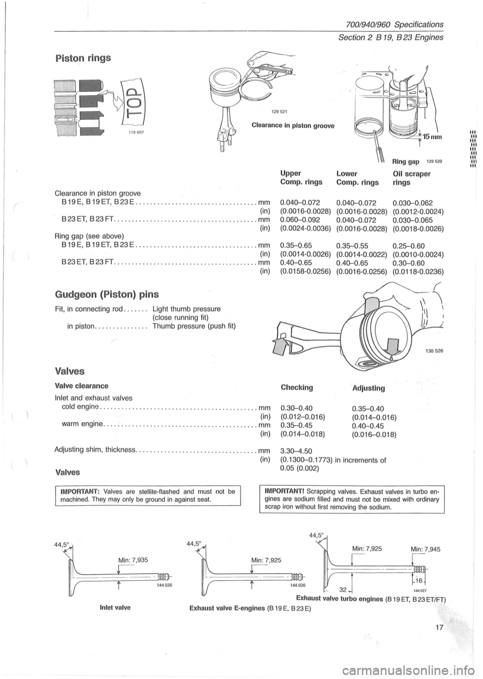
P iston rings
129521
Clearance In piston groove
Clearance in piston groove
819 E, 819 ET, 823 E .................................. mm
(in)
823ET, 823FT .............. .......................... mm
(in)
Ring gap (see above)
819E, 819ET, 823E .................................. mm
(in)
823ET, 823FT ................ .......... .............. mm
Gudgeon (Piston ) pins
Fit, in connecting rod. . . . . .. Light thumb pressure
(close running fit)
in piston. . . . . . . . . . . . . .. Thumb pressure (push fit)
Valves
Valve clearance
Inlet
and exhaust valves
(in)
cold engine ............................................ mm
(in) warm engine ........................................... mm
(in)
Adjusting shim, thickness .................................. mm
(in)
Valves
Upper
Camp.
rings
0.040-0 .072
(0. 0016-0.0028)
0.060-0 .092
(0.0024-0.0036)
0 .35-0.65
(0.0014 -0 .0026)
0.40-0 .
65
(0.0158-0.0256)
Checking
0.30-0.40
(0.012-0.Q16)
0.35-0.45
(0.014-0.018)
3 .
30-4.50
Ring gap 129 520
Lower Oil scraper
Camp.
rings rings
0.040-0.072 0.030-0.062
(0.0016 -0 .0028) (0.0012 -0.0024)
0.040-0.072 0.030-0.065
(0.0016-0.0028) (0.0018-0.0026)
0.35-0.55 0.25-0.60
(0.0014-0.0022) (0.0010-0.0024)
0.40-0.65 0.30-0.60
(0.0016-0.0256) (0.0118-0.0236)
'Adjusting
0.35-0.40
(0. 014-0 .016)
0.40-0.45
(0. 016-0.018)
(0.1300-0 .1773)
in increments of
0.05 (0.002)
IMPORTANT: Valves are stellite-flashed and must not be machined . They may only be ground in against seat. IMPORTANT! Scrapping valves. Exhaust valves in turbo engines are sodium filled and must not be mixed with ordinary
scrap iron without first removing the sodium.
Min: 7,935
Inlet valve
44,5°
44,5 °
Min: 7,945
144027
Exhaust valve turbo engines (8 19 ET, 823 ET/FT)
Exhaust valve E-engines (8 19 E, 823 E)
17
III' III III
III
III ,111 III ·111 III
Page 39 of 168
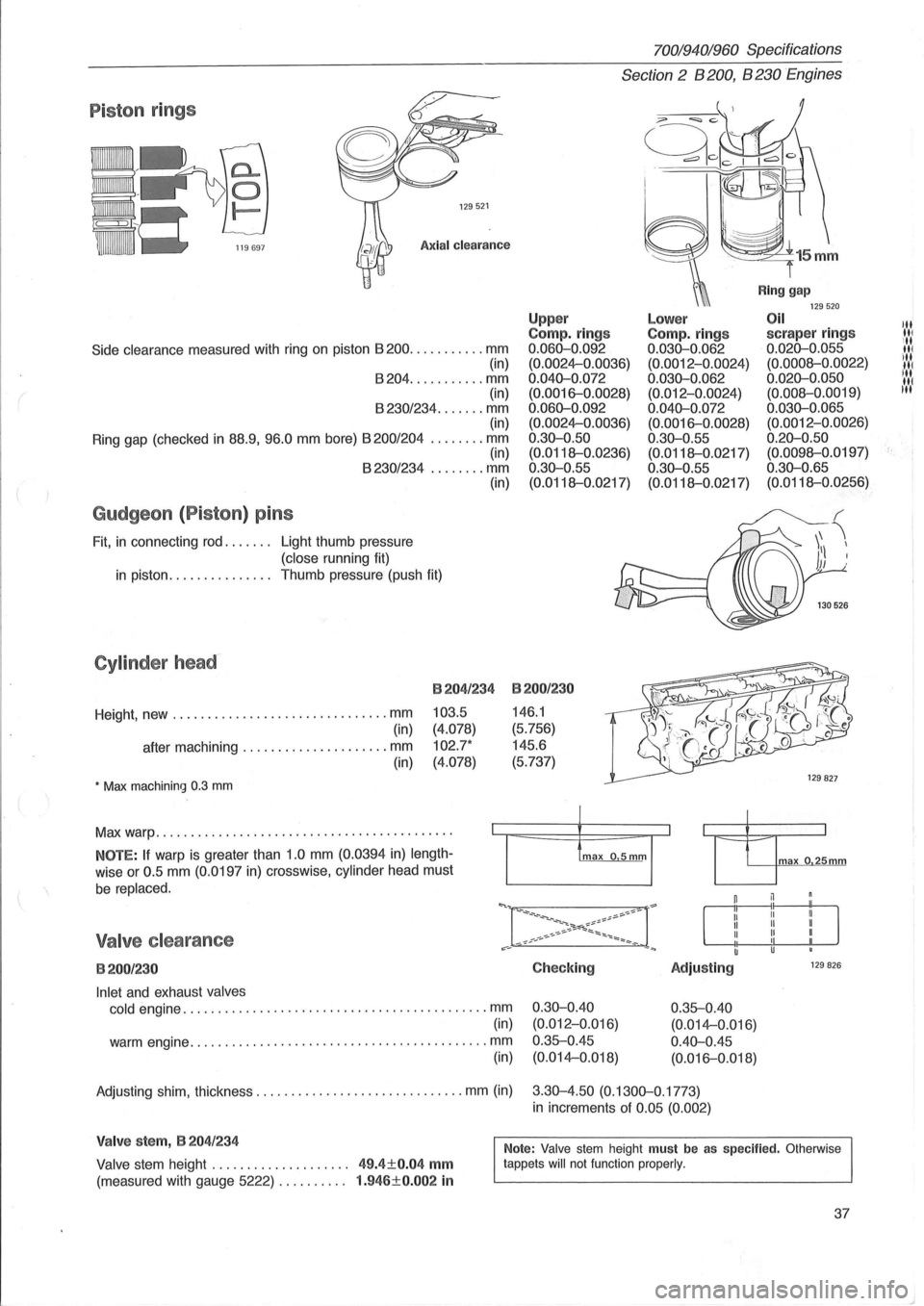
Piston rings
129521
Axial clearance
Side clearance measured with ring on piston 8200 ........... mm
(in)
8204 ........... mm
(in)
8230/234 ....... mm (in)
Ring gap (checked
in 88.9, 96.0 mm bore) 8200/204 ........ mm (in) 8230/234 ........ mm
Gudgeon (Piston) pins
Fit, in connecting rod. . . . . .. Light thumb pressure
(close running fit) (in)
in piston.
. . . . . . . . . . . . .. Thumb pressure (push fit)
Cylinder head-
Height, new ............................... mm
(in)
after machining
..................... mm
(in)
• Max machining 0.3 mm
B204/234
103.5
(4.078)
102.7*
(4.078)
Max warp .......................................... .
NOTE: If warp is greater than 1.0 mm (0.0394 in) length
wise or 0.5 mm (0.0197 in) crosswise, cylinder head must
be replaced.
Valve clearance
B200/230
Inlet and exhaust valves
cold
engine ............................................ mm
(in)
warm engine
........................................... mm
(in)
70019401960 Specifications
Section 2 B 200, B 230 Engines
Upp er Compo rings 0.060-0.092
(0.0024-0.0036)
0.040-0.072 (0.0016-0.0028)
0.060-0.092 (0.0024-0.0036)
0.30-0.50
(0.0118--0.0236)
0.30-0.55
(0.0118--0.0217)
B200/230
146.1
(5.756)
145.6
(5.737)
Checking
0.30-0.40 (0.012-0.Q16)
0.35--0.45 (0.014-0.018)
Lower Compo rings 0.030-0.062 (0.0012-0.0024)
0.030-0.062 (0.012-0.0024)
0.040-0.072 (0.0016-0.0028)
0 .30-0.55
(0.0118--0.0217)
0.30-0.55
(0.0118--0.0217)
Adjusting
0.35--0.40
(0.014-0.016)
0.40-0.45 (0.016-0.018)
Ring gap 129520 Oil scraper rings 0.020-0.055
(0.0008--0.0022)
0.020-0.050 (0.008--0.0019)
0.030-0.065 (0.0012-0.0026)
0.20-0.50 (0.0098--0.0197)
0.30-0.65 (0.0118--0.0256)
max o 25mm
129 826
Adjusting shim, thickness .............................. mm (in) 3.30-4.50 (0.1300-0.1773)
in increments of 0.05 (0.002)
Valve stem, B 204/234
Valve stem height . . . . . . . . . . . . . . . . . . .. 49.4±0.04 mm
(measured with gauge 5222) . . . . . . . . .. 1.946±0.002 in
Note: Valve stem height must be as specified. Otherwise
tappets will not function properly.
37
III III
ill III ill
IN liN
t·
Page 101 of 168
(
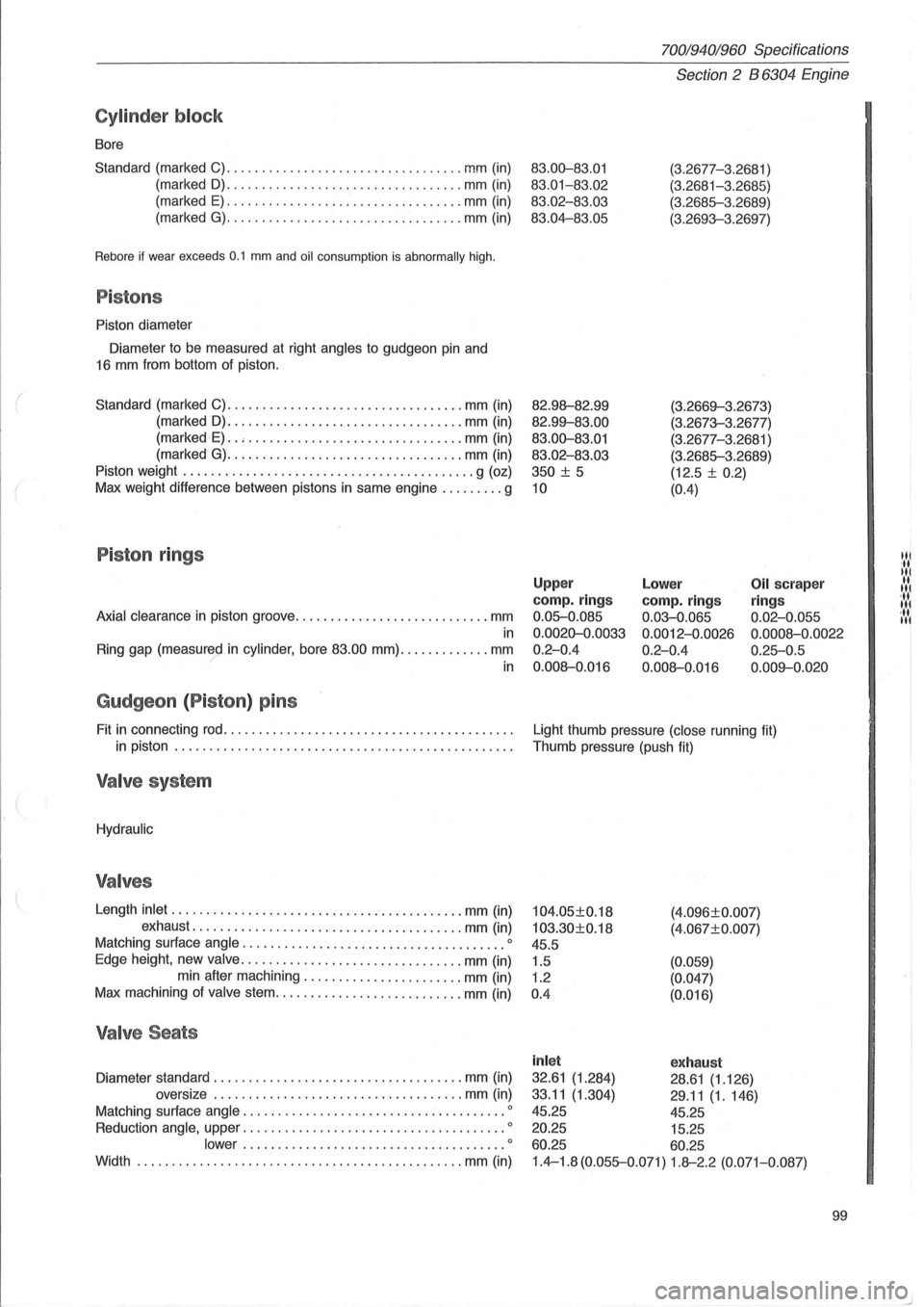
Cylinder block
Bore
Standard (marked C)
........................... ....... mm (in)
(marked
D) ........... ....................... mm (in)
(marked
E) .................................. mm (in)
(marked
G) ................... . .............. mm (in)
Rebore if wear exceeds 0.1 mm and oil consumption is abnormally high.
Pistons
Piston diameter
Diameter to be measured at right
angles to gudgeon pin and
16 mm from bottom of piston.
Standard (marked C)
.................................. mm (in)
(marked
D): ................................ . mm (in)
(marked
E) .. , ........................ ....... mm (in)
(marked
G) ............ ...................... mm (in)
Piston weight
.......................................... g (oz)
Max weight difference between pistons in same engine
......... g
Piston rings
Axial clearance in piston groove ............................ mm
in
Ring gap (measured in cylinder, bore 83.00 mm) ............. mm ? in
Gudgeon (P iston ) pins
Fit in connecting rod ......................................... .
in piston
................................................ .
Valve system
Hydraulic
Valves
Length inlet ...... .................................... mm (in)
exhaust
.............. ......................... mm (in)
Matching surface
angle .................................. .... 0
Edge height, new valve ................................ mm (in)
min after machining .
...................... mm (in)
Max machining of
valve stem ................ ........... mm (in)
Valve Seats
Diameter standard .................................... mm (in)
oversize
.... ................................ mm (in)
Matching surface
angle .......................... ............ 0
Reduction angle, upper ...................................... 0
lower ................. ....... .............. 0
Width ...................................... ... ...... mm (in)
70019401960 Specifications
Section 2 B 6304 Engine
83.00-83.01
83.01-83 .02
83.02-83.03
83.04-83.05
82.98--82.99
82.99--83.00
83.00-83.01
83.02 -83.03
350
± 5
10
(3.2677-3 .2681 )
(3.2681-3.2685)
(3.2685-3 .2689)
(3.2693-3.2697)
(3.2669--3.26 7
3)
(3.2673-3.2677)
(3.2677-3.
2681 )
(3.2685-3.2689)
(12.5 ±
0.2)
(0.4)
Upper
camp. rings
0.05-0.085
0.0020-0.0033
0.2-0.4
0.008--0.016
Lower
camp. rings
0.03-0.065
0.0012-0.0026
0.2-0.4
0.008--0.016
Oil scraper
ring s
0.02-0.055
0.0008 -0.0022
0.25-0.5
0.009--0 .020
Light thumb pressure (close running fit)
Thumb pressure (push fit)
104.05±0.18
103.30±0.18
45.5
1.5
1.2
0 .4 (4
.
096±0.007)
(4.067±0. 007)
(0.059)
(0.047)
(0.016)
inl et exhaust
32.61 (1.284) 28.61 (1.126)
33.11
(1.304) 29 .11 (1.146)
45.25 45.25
20.25 15.25
60.25 60.25
1.4-1.8 (0.055-0.071) 1.8--2.2 (0.071-0.087)
99
Itl
It
Itl
.... 1 '11 Itl ... Itl
Page 120 of 168
70019401960 Specifications
Section 3 Electrical system
Section 3 Electrical system
Group 31 Battery............................... 118
Group 32 Alternator. . . . . . . . . . . . . . . . . . . . . . . . . . . .. 118
Group 33 Starter motor . . . . . . . . . . . . . . . . . . . . . . .
.. 123
Group 35 Lighting......... . . . . . . . . . . . . . . . . . . . .. 127
Group
37 Fuses.... . . . . . . . . . . . . . . . . . . . . . . . . . . .. 128
Group 38 Instrumentation . . . . . . . . . . . . . . . . . . . . . .. 137
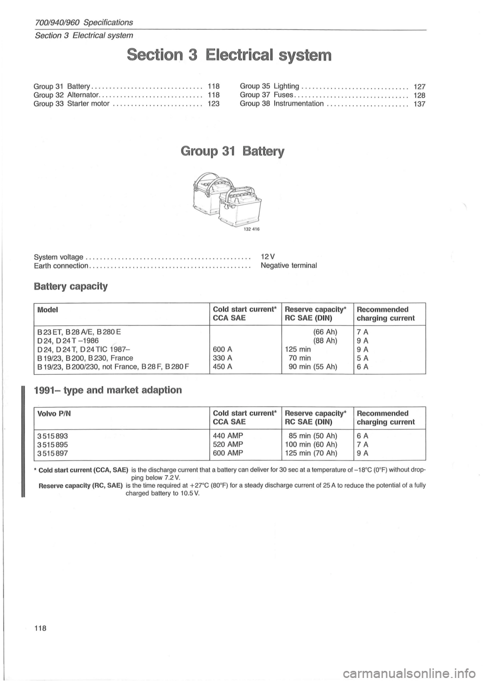
Group 31 Battery
System voltage . . . . . . . . . . . . . . . . . . . . . . . . . . . . . . . . . . . . . . . . . . . . . . 12 V
Earth connection. . . . . . . . . . . . . . . . . . . . . . . . . . . . . . . . . . . . . . . . . . . . . Negative terminal
Battery capacity
Model Co
ld start current*
Reserve capacity* Recommended
CCA SAE
RC SAE (DIN) charging current
B23ET, B28A1E, B280E (66 Ah) 7A
024, 0 24 T -1986 (88 Ah) 9A
024,024 T, 024 TIC 1987-600 A 125 min 9A
B 19/23, B 200, B 230, France 330
A 70 min 5A
B 19/23, B 200/230, not France, B 28 F, B 280 F 450 A 90 min (55 Ah) 6A
1991-type and market adaption
Volvo PIN Cold start current*
Reserve capacity*
Recommended
CCA SAE
RC SAE (DIN) ·charging current
3515893
440 AMP 85 min (50 Ah) 6A
3515895 520 AMP 100 min (60 Ah) 7A
3515897 600 AMP 125 min (70 Ah) 9A
• Cold start current (CCA, SAE) is the discharge current that a battery can deliver for 30 sec at a temperature of -18°C (O°F) without drop
ping below 7 .2 V.
Reserve capacity (RC, SAE) is the time required at + 2rC (80°F) for a steady discharge current of 25 A to reduce the potential of a fully charged battery to 10.5 V .
118
Page 129 of 168
70019401960 Specifications
Section 3 Electrical System
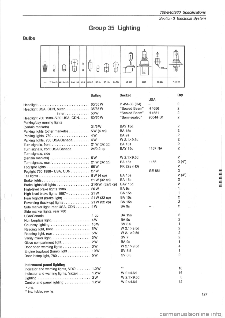
Group 35 Lighting
Bulbs
.~<
~ w W ~ ~ ffi 8 W
j At t ~ 'I lkU
.. W 2x4,6d W 2.1x9.5d BAY 15d VS 7 SV 8,5 BA9s BA 155 BA 155 GE B81 9004 PK 225 P 43t·38
( Rating Socket Qty
USA
Headlight ................... ........... 60/55W P
45t-38 (H4) 2
Headlight
USA, CON, outer .............. 35/35W "Sealed Beam" H4656 2
inner
.............. 50W "Sealed Beam" H4651 2
Headlight 760 1988--/780
USA, CON ...... 50/70W "Semi-sealed" 9004/HB1
2
Parking/day running
lights
(certain markets) 21/5W BAY 15d 2
Parking
lights (other markets) ............ 5W (4 cp) BA 15s 2
Parking lights, 780
...................... 4W BA 9s 2
Parking
lights, 780 USA/Canada .......... 4W W 2.1 x9.5d 2
Turn signals, front
...................... 21 W (32 cp) BA
15s 2
Turn signals, front USA/Canada 24/2.2
cp
BAY 15d 1157
NA 2
Turn signals,
side
(certain markets) .
...................... 5W W 2.1 x9.5d 2
Turn signals, rear ..
..................... 21 W (32 cp) BA
15s 1156 2
(4*)
Fog/spot
lights ....... .................. 55W PK 22s (H3) 2
Foglight 760 1988--
USA, CON ........... 27W GE 881 2 "' Tail lights .............................. 5W (4 cp) BA
15s 2
(4*) ' .... ,
Brake lights ............................ 21 W (32 cp) BA 15s 2 :':':1
Brake lights/tail
lights ................... 21/5 W, (3213 cp) BAY 15d 2 ':.:.: High-level brake lights 1986 .............. 20W BA 9s
High-level brake lights 1987-..........
.. 21W BA 15s
Rear foglight (brake
light) ................ 21 W (32 cp) BA
15s 2
Reversing (back-up)
lights ............... 21 W (32 cp) BA
15s 2
Side marker light, rear USA, CON ........ 4W BA
9s 2
Side marker
lights, rear 780
USA/Canada 4
cp
BA 15s 2
Numberplate
light ....................... 4W BA 9s 2
Courtesy lighting
....................... 10W SV 8.5
Reading
light, front. ..................... 5W W 2 .1 x 9.5d 2
Reading
l ight, rear ...................... 5W W 2.1 x 9.5d 2
Vanity mirror
light ....................... 3W SV 7 2
Glove compartment light. ................ 2W BA 9s
Door
open warning lights ................ 3W W 2.1 x 9.5d 4
Engine bay/boot (trunk)
light ............. 10W SV 8 .5 1
Ooor instep light, 780
................... 5W SV 8.5 2
Instrum
ent panel lighting
Indicator and warning lights, VDO ........ 1.2W ** 16
Indicator and warning lights, Yazaki ....... 1.2W W 2x4.6d 16
Lighting ............................... 3W W 2.1 x9.5d 3
Control and panel lighting ......
..... .... 1.2W W 2x4.6d 12
• 780. H Inc . holder. see fig . 127
)
Page 130 of 168
7001940;'960 Specifications
Section 3 Electrical System
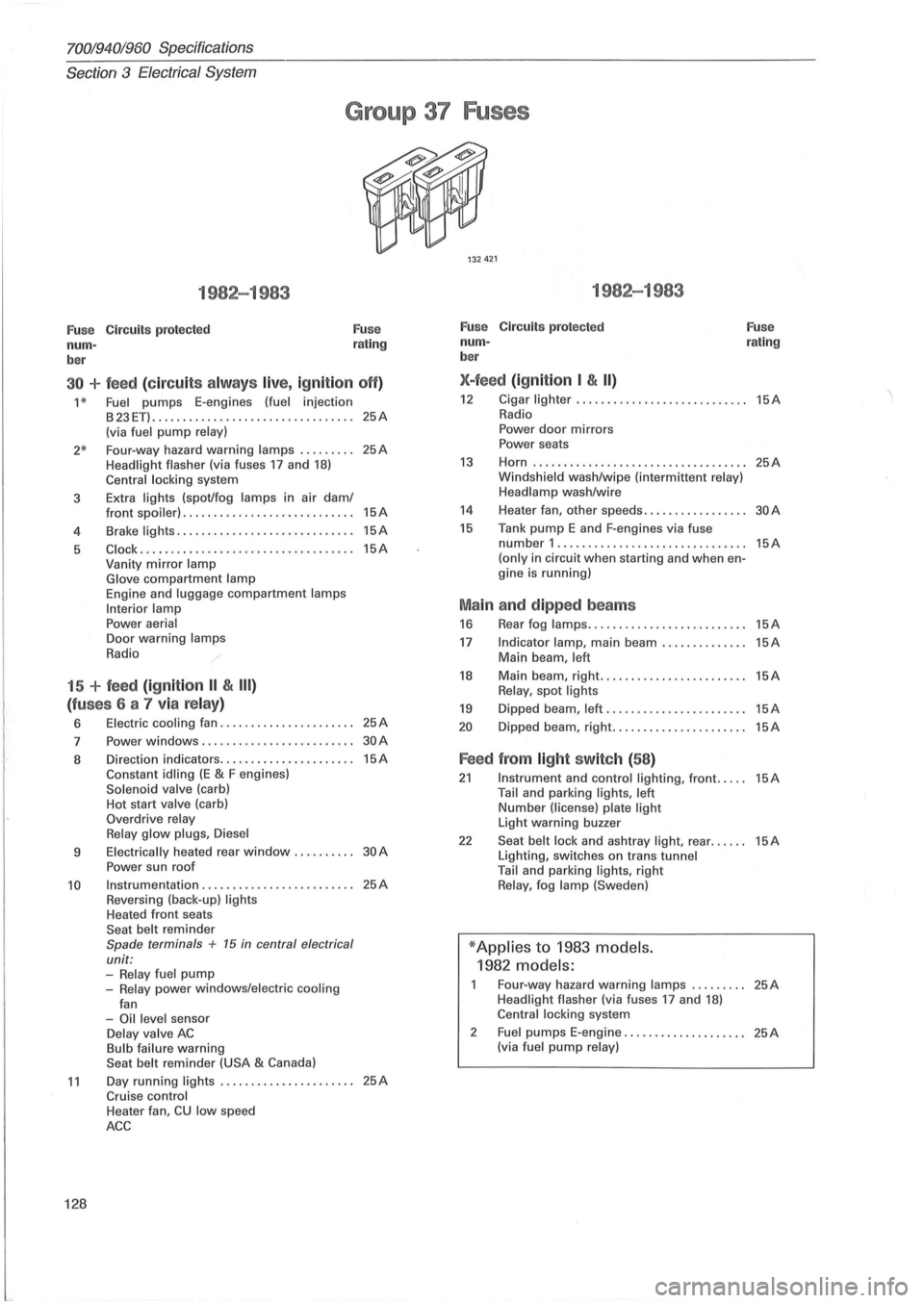
Group 37 Fuses
1982-1983
Fu se Circuits protected
num -
ber Fuse
rating
30 + feed (c ir cu its alw ays live, ig nition off)
1 * Fuel pumps E-engines (fuel injection
B23ET) ........................... ...... 25A (via fuel pump relay)
2* Four-way hazard warning lamps ........ . 25A Headlight flasher (via fuses 17 and 18) Central locking system
3 Extra
lights (spot/fog lamps in air dam/
4
5
front spoiler) ............................ 15A
Brake lights ............. ................ 15A
Clock .......................... ......... 15A Vanity mirror lamp
Glove compartment lamp Engine and luggage compartment lamps
Interior lamp
Power aerial Door warning lamps
Radio
15 + feed (ignition II & III)
(fu ses 6 a 7 via relay)
6 Electric cooling fan ...................... 25A
7 Power windows .................. ....... 30A
8 Direction indicators ...................... 15A Constant idling (E & F engines) Solenoid valve (carb)
Hot start valve (carb)
Overdrive relay
Relay glow plugs , Diesel
9 Electrically heated rear window. . . . . . . . .. 30 A
Power sun roof
10 Instrumentation ...................... , .. 25A Reversing (back-up) lights Heated front seats
Seat belt reminder Spade terminals + 15 in central electrical
unit:
-Relay fuel pump -Relay power windows/electric cooling
fan
-Oil level sensor Delay valve AC Bulb failure warning
Seat belt reminder (USA & Canada)
11 Day running lights ...................... 25A Cruise control
128
Heater fan, CU low speed
ACC
1982-1983
Fuse Circuits protected
num -
ber
X-feed (ign ition I & II)
Fuse rating
12 Cigar lighter ... ......................... 15A Radio
Power door mirrors
Power seats
13 Horn ................................ ... 25A Windshield wash/wipe (intermittent relay)
Headlamp wash/wire
14 Heater fan, other speeds. . . . . . . . . . . . . . . .. 30 A
15 Tank pump E and F-engines via fuse number 1 .............................. . (only in circuit when starting and when engine is running)
Ma in and dipped beams
16 Rear fog lamps ......... .................
17 Indicator lamp, main beam .............. Main beam, left
18 Main beam, right. ....................... Relay, spot lights
19 Dipped beam, left .......................
20 Dipped beam, right ......................
Feed from light switch (58 )
15A
15A
15A
15A
15A
15A
21 Instrument and control lighting, front ..... 15A Tail and parking lights, left Number (license) plate light Light warning buzzer
22 Seat belt lock and ashtray light, rear ...... 15A Lighting, switches on trans tunnel
Tail and parking lights, right Relay, fog lamp (Sweden)
* Applies to 1983 models.
1982 models:
Four-way hazard warning lamps ......... 25A Headlight flasher (via fuses 17 and 18) Central locking system
2
Fuel pumps E-engine .................... 25A (via fuel pump relay)
Page 131 of 168
(
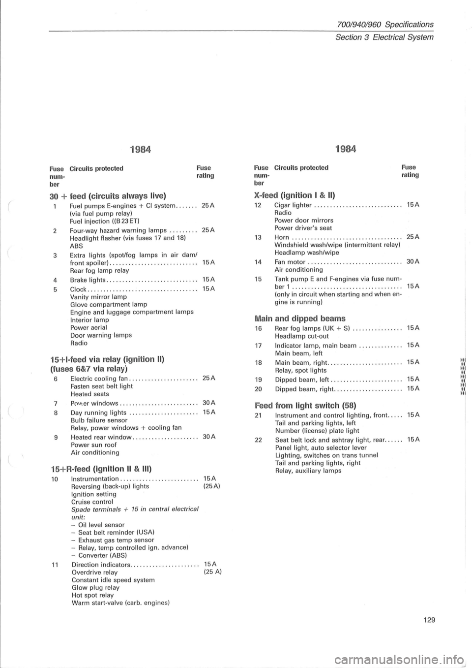
1984
Fuse Circuits protected Fuse
num-rating
ber
30 + feed (circuit s alw ays live)
Fuel pumps E-engines + CI system ....... (via fuel pump relay)
Fuel i njection ((B 23 ET)
2 Four-way
hazard
warning lamps ......... Headlight flasher (via fuses 17 and 18)
ABS
3 Extra lights (spot/fog lamps in
air dam/ front spoiler) . ................ ... .. ......
Rear fog lamp relay
4 Brake lights .....
.. .............•........
5 C lock ....... ............. ............. ..
Vanity mirror lamp Glove compartment lamp Engine and luggage compartment lamps
Interior lamp Power aerial Door warning lamps
Radio
15+I-feed via relay (ignition II)
(fuses 6&7 via relay)
6 Electric cooling fan ................ ...... Fasten seat belt light Heated seats
7
p()\J\; er windows ........... . •.... ........
8 Day
running
lights ..... .......... ....... Bulb failure sensor Relay, power windows + cooling fan
9 Heated
rear
window ................. ....
Power sun roof Air conditioning
15+R-feed (ignition II & III)
10 Instrumentation ........................ .
Reversing (back-up) lights Ignition setting Cruise control
Spade terminals + 15 in central electrical
unit: -Oil level sensor
-Seat belt reminder (USA) -Exhaust gas temp sensor
-Relay, temp contro lled ign. advance)
-Converter (ABS)
25A
25A
15A
15A
15A
25A
30A
15A
30A
15A (25A)
11 Direction indicators.. .. .... .. . .... .. ..... 15A Overdrive relay (25 A) Constant idle speed system Glow plug relay Hot spot relay Warm start-valve (carb. engines)
70019401960 Specifications
Section
3 Electrical System
1984
Fuse C ircuit s protected Fuse
num-rating
ber
X-feed (ignition I & II)
12 Cigar lighter ...... ..............•....... 15A
Radio
Power door mirrors Power driver's seat
13 Horn ...... ........... .. ................ 25A
Windsh ield wash/wipe (interm ittent relay)
Headlamp wash/wipe
14 Fan motor .................. ......... ... 30A
Air conditioning
15 Tank pump E and F-engines via fuse num-ber 1 ...... ...................... ....... 15A
(only in circuit when starting and when en-
gine is running)
Main and dipped beams
16 Rear fog lamps (UK + S) ................ 15A
Headlamp cut-out
17 Indicator lamp, main beam .............. 15A
Main beam , left
18 Main beam, right .......•... ............. 15A IN
Relay, spot lights "I
19 Dipped beam, left ...... ................. 15A IIII( II.
20 D ipped beam, right ...........•.......... 15A "I II. II
Feed from light switch (58)
21 Instrument and control lighting, front ..... 15A
Tail and parking lights, left Number (license) plate light
22 Seat belt lock and ashtray light, rear ...... 15A
Panel light, auto selector lever Lighting, switches on trans tunnel Tail and parking lights, right Relay, auxiliary lamps
129
Page 132 of 168
70019401960 Specifications
Section
3 E lectrical System
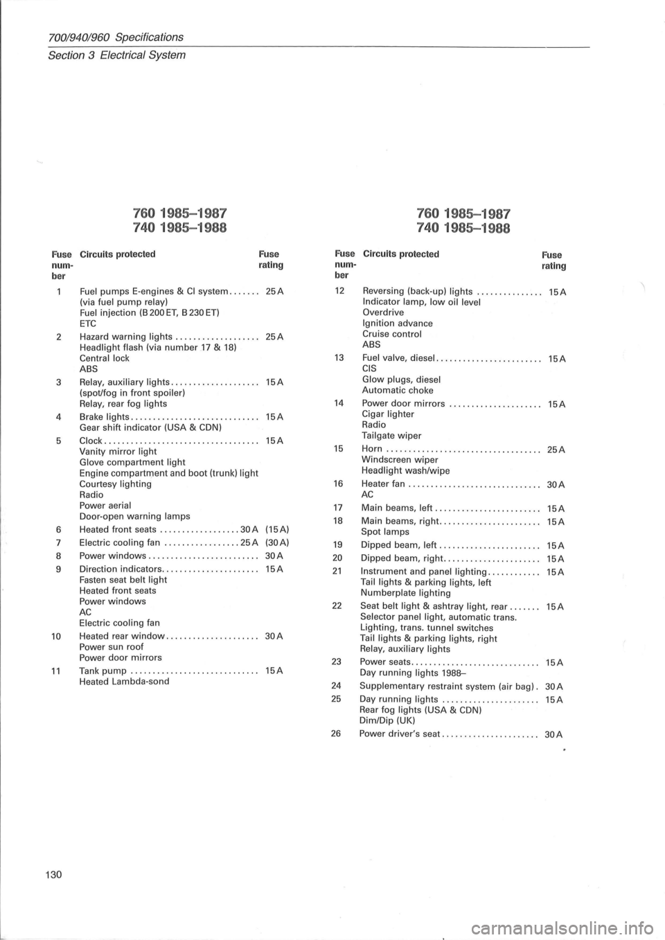
760 1985-1987 760 1985-1987
740 1985-1988 740 1985-1988
Fuse C ircuit s protected Fuse Fuse Circuits protected
Fuse nurn- r
ating nurn-rating ber ber
Fuel pumps
E-engines & CI system ....... 25A 12 Reversing (back-up) lights ............... 15A
(via fuel pump relay) Indicator lamp, low oil level Fuel injection (B 200 ET, B 230 ET) Overdrive
ETC Ignition advance
2 Hazard
warning
lights ................... 25A Cruise control
Headlight flash
(via number .17 & 18) ABS
Central lock
13 Fuel valve, diesel ........................ 15A ABS CIS
3 Relay, auxiliary lights .................... 15A Glow plugs, diesel
(spot/fog in front spoiler) Automatic choke
Relay , rear fog lights 14 Power door mirrors ..................... 15A
4 Brake lights .
............................ 15A Cigar lighter
Gear shift indicator (USA & CDN) Radio
5
Clock ................................... 15A Tailgate wiper
Vanity mirror light 15 Horn ..... ............................. . 25A
Glove compartment light Windscreen wiper
Engine compartrTJent and boot (trunk) light Headlight wash/wipe
Courtesy lighting 16 Heater fan .............................. 30A Radio AC Power aerial 17 Main beams, left ........................ 15A Door -open warning lamps 18 Main beams, right ....................... 15A 6 Heated
front seats .......... ........ 30 A (15A) Spot
lamps 7 Electric cooling fan ................. 25 A (30A) 19 Dipped beam, left ....................... 15A 8 Power windows ......................... 30A 20 Dipped
beam, right ...................... 15A 9 Direction
indicators ...................... 15A 21 Instrument and panel lighting ............ 15A Fasten seat belt light Tail lights & parking lights, left Heated front seats Numberplate lighting Power windows 22 Seat belt light & ashtray light, rear ....... 15A AC Selector panel light, automatic trans. Electric cooling fan
Lighting, trans. tunnel switches 10 Heated rear window ..................... 30A Tail lights & parking lights, right
Power sun roof Relay , auxiliary lights Power door mirrors 23 Power seats ............................. 15A 11 Tank pump ............................. 15A Day running lights 198B-Heated Lambda-sond 24 Supplementary restraint system (air bag). 30A
25 Day running lights ................... ... 15A Rear fog lights (USA & CDN) Dim/Dip (UK)
26 Power driver's seat ...................... 30A
130