1982 CHEVROLET CAMARO coolant
[x] Cancel search: coolantPage 736 of 875

GM – CAMARO 1982-1992 – Repair Guide (Checked by WxMax) 736
The mass air flow systems measure the
mass of air that is drawn into the
engine cylinders, rather than just the vo lume. The sensor contains a hot-wire
sensing unit, which is made up of an electronic balanced bridge network.
Whenever current is suppli ed to the sensor, the bridge is energized and the
sensing hot-wire is heated. As the air enter s the mass air flow sensor, it passes
over and cools the hot wire. When the hot wire is cooled, it's resistance changes
and additional current is needed to k eep the bridge network balanced. This
increase in current is sent to the computer as a voltage signal and is used to
calculate the mass of the incoming air. The ECM uses this information to\
determine the duration of fuel injection pulse, ignition timing and EGR operation.
The speed density systems calculate the volume of air moving through the
intake. The ECM establishes the speed fact or through a signal from the ignition
module. The Manifold or Intake Air Temperature (MAT/IAT) and the Engine
Coolant Temperature (ECT) sensors work together to assure that proper
temperature information gets to the ECM wh ile the Manifold Absolute Pressure
(MAP) sensor monitors the changes in m anifold pressure which results from
changes in engine loading. These three se nsors contribute to the density factor.
Together, these inputs (engine speed, coolant temperature sensor, etc ...) are
the major determinants of the air/fuel mixture delivered by the fuel injection
system.
The following engines and fuel managem ent systems are covered in this
section:
• 1985-1989 2.8L MPFI - Mass Air Flow
• 1990-1992 3.1L MPFI - Speed Density
• 1985-1989 5.0L and 5.7L TPI - Mass Air Flow
• 1990-1992 5.0L and 5.7L TPI - Speed Density
Relieving Fuel System Pressure
1. Disconnect the negative battery cable to prevent fuel discharge if the key
is accidentally turned to the RUN position.
2. Loosen the fuel filler cap to reliev e the tank pressure and do not tighten
until service has been completed.
3. Connect J-34730-1 fuel pressure gauge or equivalent, to the fuel
pressure test valve. Wrap a shop towel around the fitting while
connecting the gauge to prevent spillage.
4. Place the end of the bleed hose into a suitable container and open the
valve to relieve the fuel system pressure.
ELECTRIC FUEL PUMP
REMOVAL & INSTALLATION
The fuel pump is part of t he fuel sender assembly located inside the fuel tank.
Page 739 of 875

GM – CAMARO 1982-1992 – Repair Guide (Checked by WxMax) 739
3. Make sure the ignition switch has
been in the OFF position for at least 10
seconds and that all accessories are OFF.
4. Turn the ignition switch ON and the pump will run for about 2 seconds.
Note the system pressure with t he pump running, it should be between
40-47 psi.
The ignition switch may have to be cycled to the ON position more than once to
obtain maximum pressure. It is also norma l for the pressure to drop slightly
when the pump first stops, but it should then hold steady.
5. If the pressure is not as specified, verify that fuel pump operation is
heard in the tank.
6. If fuel pump operation is not heard, inspect the fuel pump relay and
wiring.
7. If fuel pump operation is heard, inspect the filter and lines for restriction.
8. Start the engine and make sure the pr essure decreases about 3-10 psi at
idle.
9. If fuel pressure does not decrease, inspect the fuel pressure regulator
and hose.
10. Disconnect the fuel pressure gauge.
THROTTLE BODY
REMOVAL & INSTALLATION 1. Disconnect the negative (-) battery c able and partially drain the radiator.
2. Remove the air inlet duct and unplug the IAC and TPS electrical connectors.
3. Label and disconnect the vacuum and coolant lines.
4. Disconnect the accelerator, thro ttle valve (transmission control) and
cruise control cables, as applicable.
5. Remove the throttle body attaching bolts, then separate the throttle body from the plenum.
6. Discard the gasket.
To install: 7. Install the throttle body to the plenum using a new gasket. Tighten the \
bolts to specification.
8. Engage the accelerator, throttle valve and cruise control cables, as
necessary. Make sure that the link ages do not hold the throttle open.
9. Connect the vacuum and coolant lines.
10. Install the air inlet duct and plug the IAC and TPS electrical connectors
into their sockets.
11. Connect the negative (-) battery cable and refill the radiator.
12. With the engine OFF, check to s ee that the accelerator pedal is free.
Depress the pedal to the floor and release.
Page 791 of 875

GM – CAMARO 1982-1992 – Repair Guide (Checked by WxMax) 791
3. Clean all dirt from
the area around the cover. Re move the bolts retaining
the cover to the housing. Pry the co ver from the differential housing and
allow the fluid to drain into the catch pan.
To install: 4. With the cover and housing washed free of oil and gasket material, apply sealer to the mating surfaces.
5. Using a new gasket, install the cove r and torque the bolts to 20 ft. lbs.
(27 Nm) in a clockwise pattern to in sure uniform draw on the gasket. Fill
the differential with fluid through the fi ll plug and add limited slip additive,
as required.
6. Install the parking brake cable guides, if removed.
7. The fluid level shou ld reached a level within
3/8 in. (10mm) of the filler
plug hole. Replace the filler plug. Low er the car and inspect for leaks.
COOLING SYSTEM
CAUTION - When draining the c oolant, keep in mind that cats and dogs are
attracted by the ethylene gl ycol antifreeze, and are quite likely to drink any that
is left in an uncovered container or in puddles on the ground. This will prove
fatal in sufficient quantity. Always drai n the coolant into a sealable container.
Coolant should be reused unless it is c ontaminated or several years old (in
which case it should be taken to a recycli ng facility such as a service station).
FLUID RECOMMENDATIONS
When adding or changing the fluid in the system, create a 50/50 mixture of high
quality ethylene glycol antifreeze and water.
LEVEL CHECK
Fig. 1: Fluid level marks on the cool ant recovery tank. With a warm system,
coolant level should be just below the FULL HOT mark on tank.
Page 792 of 875

GM – CAMARO 1982-1992 – Repair Guide (Checked by WxMax) 792
The fluid level may be checked by obs
erving the fluid level marks of the
recovery tank. The leve l should be between the FULL HOT and FULL COLD
mark when the system is at normal operat ing temperature. When the engine is
cold, the fluid level should be above the FULL COLD mark on the reservoir. At
normal operating temperatures, t he level should be between the ADD and the
FULL marks. Only add coolant to bring the level to the FULL mark.
CAUTION - Should it be necessary to remove the radiator cap, make sure that
the system has had time to cool, reducing t he internal pressure. If the system is
opened while the engine is st ill hot, scalding fluid and steam may be blown out
under pressure.
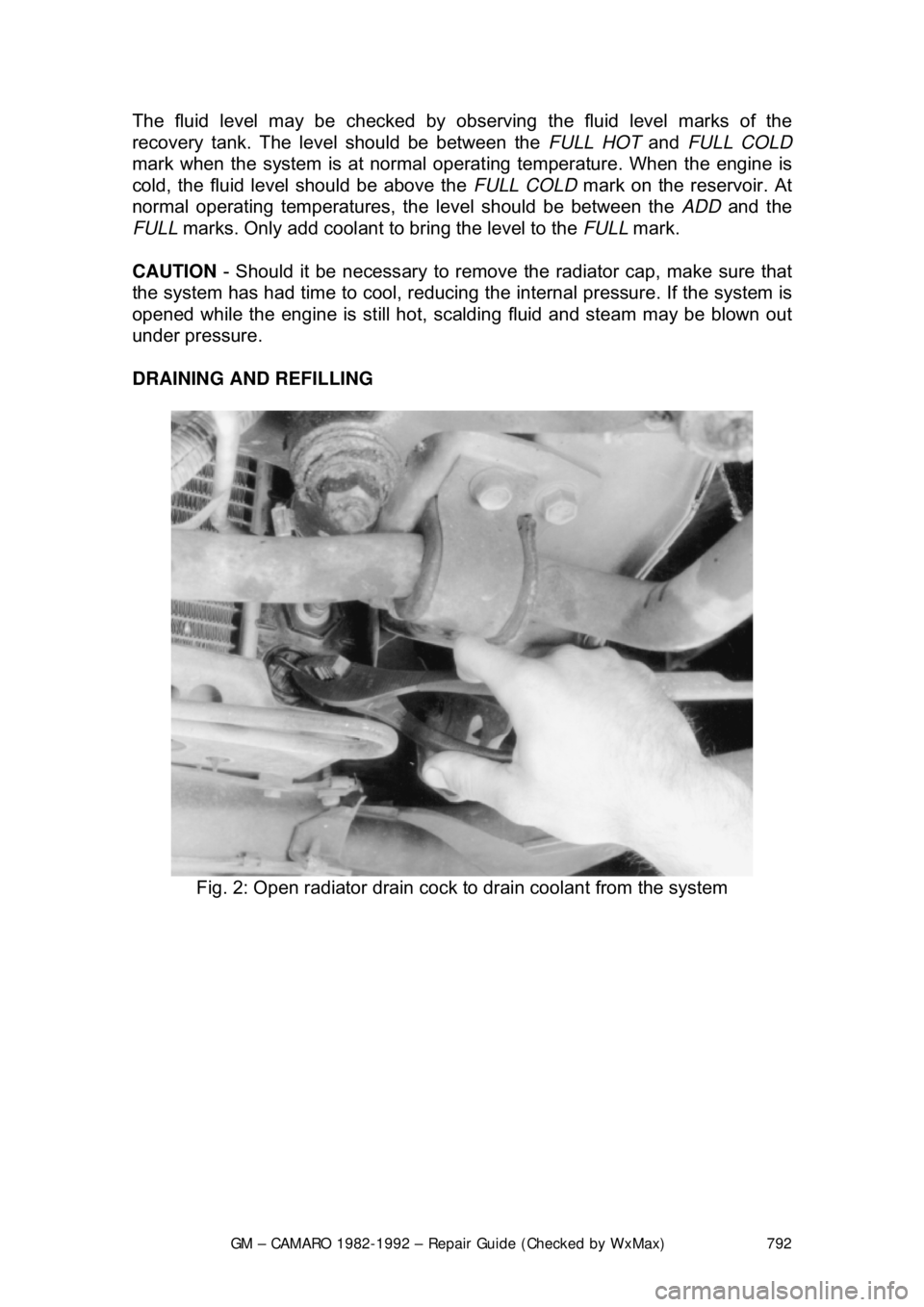
DRAINING AND REFILLING
Fig. 2: Open radiator drain cock to drain coolant from the system
Page 793 of 875

GM – CAMARO 1982-1992 – Repair Guide (Checked by WxMax) 793
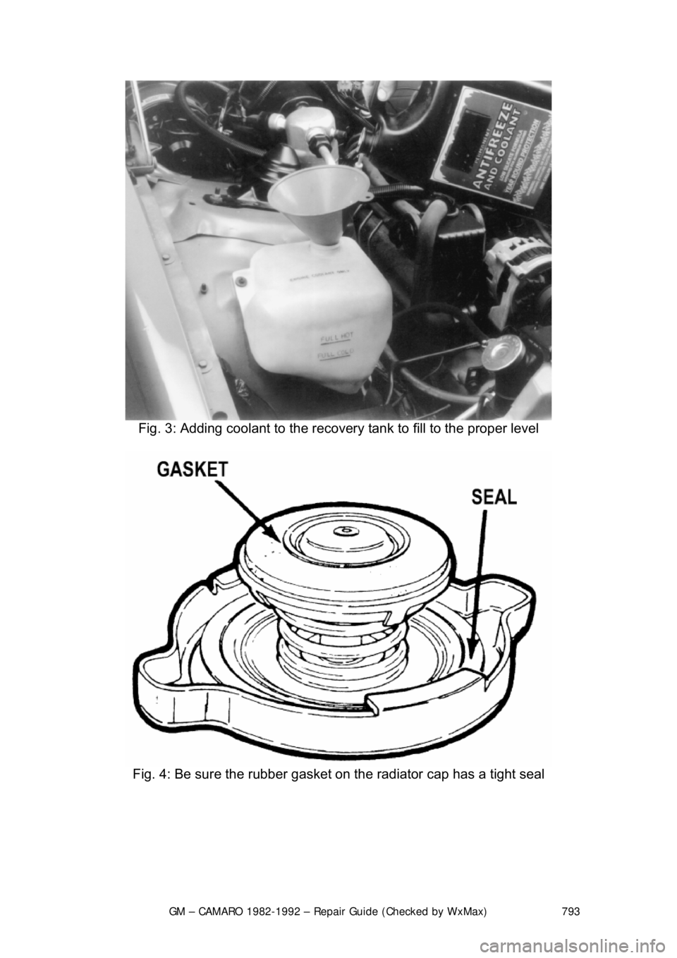
Fig. 3: Adding coolant to the recove ry tank to fill to the proper level
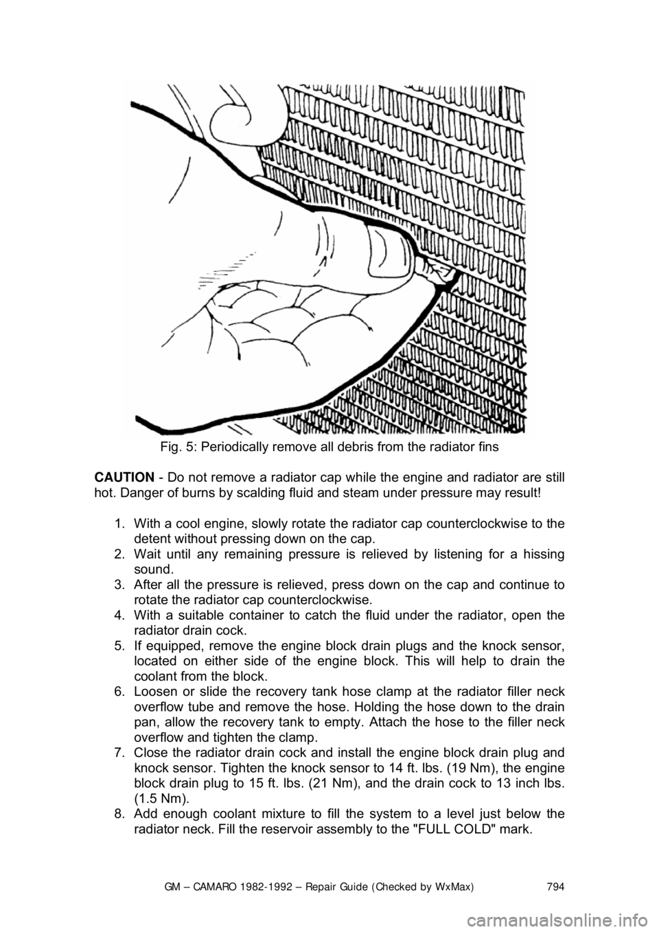
Fig. 4: Be sure the rubber gasket on the radiator cap has a tight seal
Page 794 of 875

GM – CAMARO 1982-1992 – Repair Guide (Checked by WxMax) 794
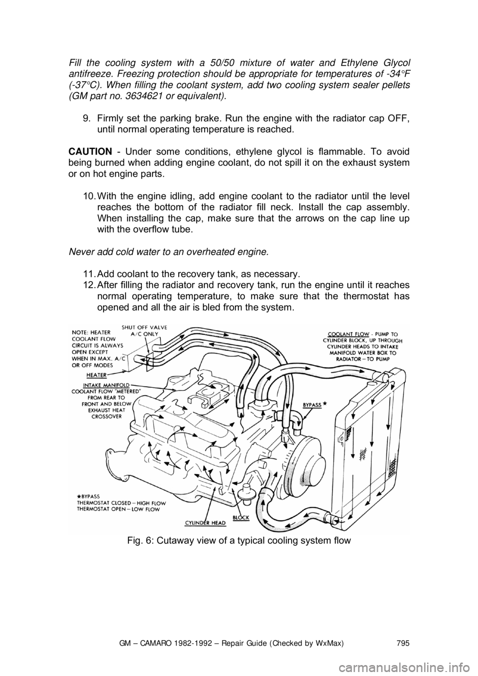
Fig. 5: Periodically remove all debris from the radiator fins
CAUTION - Do not remove a radiator cap wh ile the engine and radiator are still
hot. Danger of burns by scalding fluid and steam under pressure may result!
1. With a cool engine, slowly rotate t he radiator cap counterclockwise to the
detent without pressing down on the cap.
2. Wait until any remaini ng pressure is relieved by listening for a hissing
sound.
3. After all the pressure is relieved, press down on the cap and continue to
rotate the radiator cap counterclockwise.
4. With a suitable container to catc h the fluid under the radiator, open the
radiator drain cock.
5. If equipped, remove the engine blo ck drain plugs and the knock sensor,
located on either side of the engine block. This will help to drain the
coolant from the block.
6. Loosen or slide the recovery tank hos e clamp at the radiator filler neck
overflow tube and remove the hose. Holding the hose down to the drain
pan, allow the recovery tank to empty. Attach the hose to the filler neck
overflow and tighten the clamp.
7. Close the radiator drain cock and install the engine block drain plug and
knock sensor. Tighten the knock sensor to 14 ft. lbs. (19 Nm), the engine
block drain plug to 15 ft. lbs. (21 N m), and the drain cock to 13 inch lbs.
(1.5 Nm).
8. Add enough coolant mixture to fill the system to a level just below the
radiator neck. Fill the reservoir a ssembly to the "FULL COLD" mark.
Page 795 of 875

GM – CAMARO 1982-1992 – Repair Guide (Checked by WxMax) 795
Fill the cooling system wit
h a 50/50 mixture of water and Ethylene Glycol
antifreeze. Freezing protection should be appropriate for temperatures of -34°F
(-37°C). When filling the coolant system, add two cooling system sealer pellets
(GM part no. 3634621 or equivalent).
9. Firmly set the parking brake. Run t he engine with the radiator cap OFF,
until normal operating tem perature is reached.
CAUTION - Under some conditions, ethylene glycol is flammable. To avoid
being burned when adding engine coolant, do not spill it on the exhaust system
or on hot engine parts.
10. With the engine idlin g, add engine coolant to t he radiator until the level
reaches the bottom of t he radiator fill neck. Install the cap assembly.
When installing the cap, make sure t hat the arrows on the cap line up
with the overflow tube.
Never add cold water to an overheated engine.
11. Add coolant to the recovery tank, as necessary.
12. After filling the radiator and recovery tank, run the engine until it reaches
normal operating temperature, to ma ke sure that the thermostat has
opened and all the air is bled from the system.
Fig. 6: Cutaway view of a typical cooling system flow
Page 797 of 875

GM – CAMARO 1982-1992 – Repair Guide (Checked by WxMax) 797
The cooling system should be drained, th
oroughly flushed and refilled at least
every 30,000 miles or 24 months. This operation should be done with the \
engine cold.
1. Drain the cooling system as de scribed earlier in this section.
2. Fill the cooling system with warm water and start the engine. Run the
engine until normal operating temperature is reached.
3. At this point, turn the engine o ff and again drain the cooling system.
4. Repeat this procedure until the flui d draining from the system is nearly
colorless.
5. Remove, empty and reinstall the coolant recovery reservoir assembly.
6. Fill the cooling system with a 50/50 mixture of ethylene glycol antifreeze,
as outlined in the prev ious procedure.
BRAKE MASTER CYLINDER
FLUID RECOMMENDATIONS
When adding or replacing the brake fluid, always use a top quality fluid, such as
Delco Supreme II or equivalent DOT-3 flui d. DO NOT allow the master cylinder
reservoir to remain open for long periods of time; brake fluid absorbs moisture
from the air, reducing it s effectiveness and causing corrosion in the lines.
Avoid spilling brake fluid on any of the vehicle's painted surfaces, wiring cables
or electrical connections. Brake fl uid will damage paint and electrical
connections. If any fluid is spilled on t he vehicle, flush with water to lessen
damage.
LEVEL CHECK
Fig. 1: Check master cylinder fluid leve l against indicator on side of reservoir.
Fluid level should not be below MIN marking on reservoir.