1982 CHEVROLET CAMARO fuel type
[x] Cancel search: fuel typePage 716 of 875

GM – CAMARO 1982-1992 – Repair Guide (Checked by WxMax) 716
INJECTOR REPLACEMENT
Use care in removing injectors to prev
ent damage to the electrical connector
pins on top of the injector, the fuel injector fuel filter and nozzle. The fuel injector
is serviced as a complete assembly on ly and should never be immersed in any
type of cleaner.
SINGLE INJECTOR UNITS 1. Relieve the fuel system pressure.
2. Remove the air cleaner.
3. Detach the injector connector by squeezing the two tabs together and
pulling straight up.
4. Remove the screws securing the fuel meter cover. Note the location of
any short screws for correct placement during reassembly.
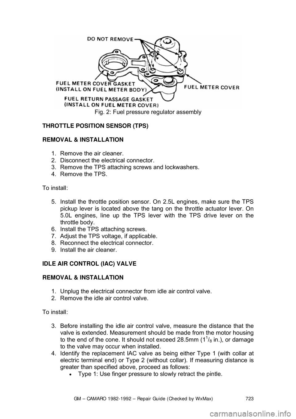
CAUTION - DO NOT remove the four screws se curing the pressure regulator to
the fuel meter cover. The fuel pressure regulator includes a large spring under
heavy tension which could cause personal injury if released.
5. With the old fuel meter gasket in place to prevent damage to the casting,
use a prytool and fulcrum to pry the inje ctor carefully until it is free from
the fuel meter body.
6. Remove the injector.
7. Remove the large O-ring and steel back-up washer at the top of the
injector cavity in the fuel meter body.
8. Remove the small O-ring located at the bottom of the injector cavity.
To Install: 9. Lubricate the new, small O-ring with automatic transmission fluid; then,
push the new O-ring on the nozzle end of the injector up against the
injector fuel filter.
10. Install the steel backup washer in the recess of the fuel meter body.
Lubricate the new large O-ring with automatic transmission fluid, then
install the O-ring directly above t he backup washer, pressing the O-ring
down into the cavity recess. The O-ri ng is properly installed when it is
flush with the casting surface.
WARNING - Do not attempt to reverse this procedure and install the backup
washer and O-ring after the injector is located in the cavity. To do so will
prevent proper seating of the O-ring in th e cavity recess which could result in a
fuel leak and possible fire.
11. Install the injector by using a pushing/twisting mo tion to center the nozzle
O-ring in the bottom of the injector cavity and aligning the raised lug on
the injector base with the notch cast into the fuel meter body. Push down
on the injector making sure it is fully seated in the cavity. Injector
installation is correct when the lug is seated in the notch and the
electrical terminals are parallel to the throttle shaft.
Page 723 of 875

GM – CAMARO 1982-1992 – Repair Guide (Checked by WxMax) 723
Fig. 2: Fuel pressure regulator assembly
THROTTLE POSITION SENSOR (TPS)
REMOVAL & INSTALLATION 1. Remove the air cleaner.
2. Disconnect the electrical connector.
3. Remove the TPS attaching screws and lockwashers.
4. Remove the TPS.
To install: 5. Install the throttle position sensor. On 2.5L engines, make sure the TPS pickup lever is located above the tang on the throttle actuator lever. On
5.0L engines, line up the TPS lever with the TPS drive lever on the
throttle body.
6. Install the TPS attaching screws.
7. Adjust the TPS volt age, if applicable.
8. Reconnect the electrical connector.
9. Install the air cleaner.
IDLE AIR CONTROL (IAC) VALVE
REMOVAL & INSTALLATION 1. Unplug the electrical connector from idle air control valve.
2. Remove the idle air control valve.
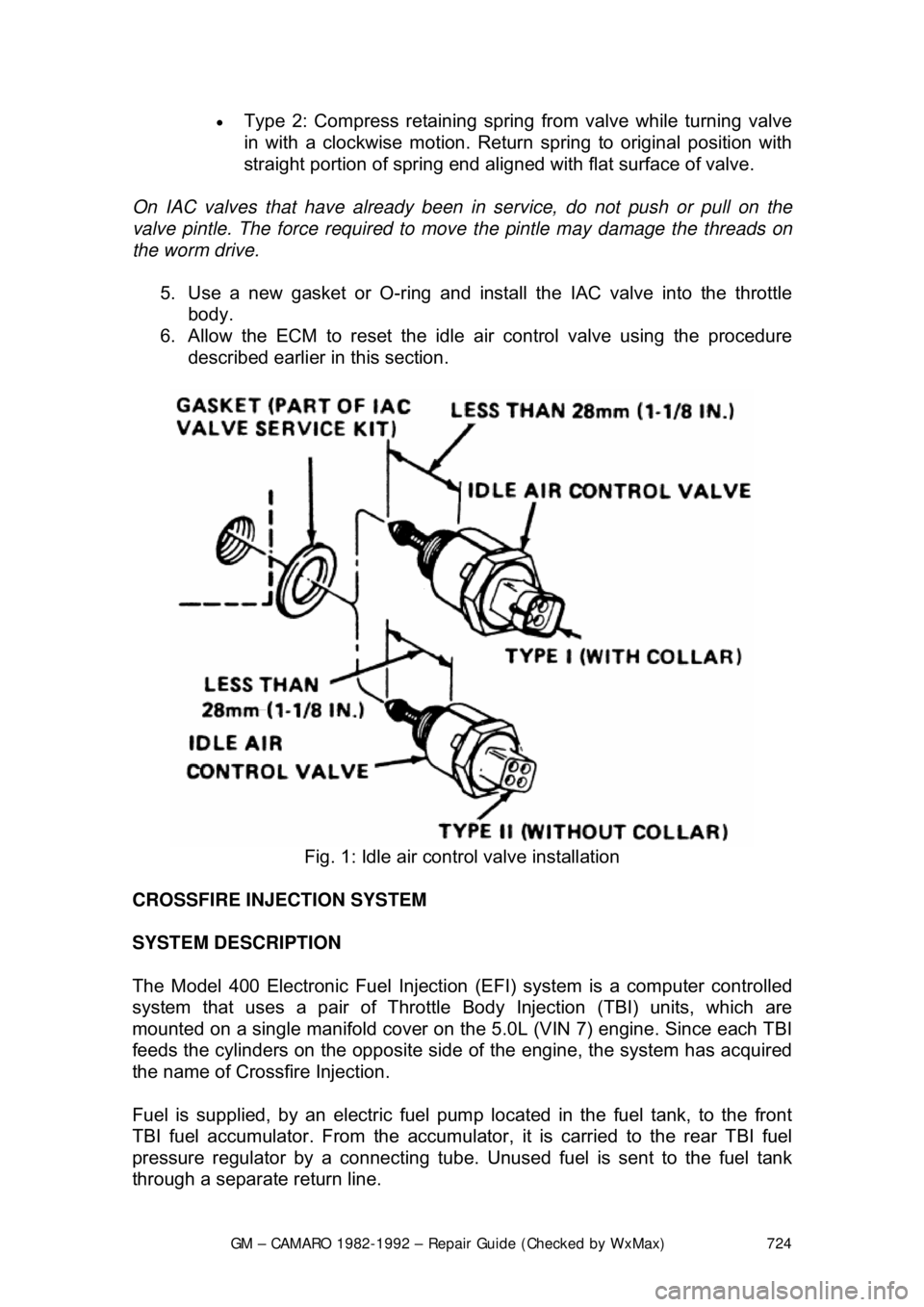
To install: 3. Before installing the idle air contro l valve, measure the distance that the
valve is extended. Measurement s hould be made from the motor housing
to the end of the cone. It should not exceed 28.5mm (1
1/8 in.), or damage
to the valve may occur when installed.
4. Identify the replacement IAC valve as being either Type 1 (with collar at
electric terminal end) or Type 2 (without collar). If measuring distance is
greater than specified abov e, proceed as follows:
• Type 1: Use finger pressure to slowly retract the pintle.
Page 724 of 875

GM – CAMARO 1982-1992 – Repair Guide (Checked by WxMax) 724
•
Type 2: Compress retaining spring from valve while turning valve
in with a clockwise motion. Return spring to original position with
straight portion of spring end aligned with flat surface of valve.
On IAC valves that have already been in service, do not push or pull on the
valve pintle. The force required to move the pintle may damage the threads on
the worm drive.
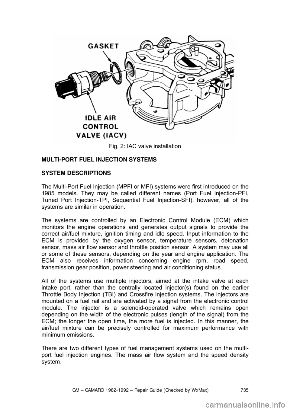
5. Use a new gasket or O-ring and install the IAC valve into the throttle body.
6. Allow the ECM to reset the idle air control valve using the procedure
described earlier in this section.
Fig. 1: Idle air control valve installation
CROSSFIRE INJECTION SYSTEM
SYSTEM DESCRIPTION
The Model 400 Electronic Fuel Injection (EFI) system is a computer controlled
system that uses a pair of Throttle Body Injection (TBI) units, which are
mounted on a single manifold cover on t he 5.0L (VIN 7) engine. Since each TBI
feeds the cylinders on the opposite side of the engine, the system has acquired
the name of Crossf ire Injection.
Fuel is supplied, by an electric fuel pum p located in the fuel tank, to the front
TBI fuel accumulator. From the accumulator, it is carried to the rear TBI fuel
pressure regulator by a c onnecting tube. Unused fuel is sent to the fuel tank
through a separate return line.
Page 735 of 875

GM – CAMARO 1982-1992 – Repair Guide (Checked by WxMax) 735
Fig. 2: IAC valve installation
MULTI-PORT FUEL INJECTION SYSTEMS
SYSTEM DESCRIPTIONS
The Multi-Port Fuel Injection (MPFI or MFI) systems were first introduced on the
1985 models. They may be called different names (Port Fuel Injection-PFI,
Tuned Port Injection-TPI, Sequential Fuel Injection-SFI), however, all of the
systems are similar in operation.
The systems are controlled by an Elec tronic Control Module (ECM) which
monitors the engine operations and gen erates output signals to provide the
correct air/fuel mixture, ignition timing and idle speed. Input information to the
ECM is provided by the oxygen sens or, temperature sensors, detonation
sensor, mass air flow sensor and throttle position sensor. A system may use all
or some of these sensors, depending on the year and engine application. The
ECM also receives information concerning engine rpm, road speed,
transmission gear position, power steer ing and air conditioning status.
All of the systems use multiple injector s, aimed at the intake valve at each
intake port, rather than the centrally lo cated injector(s) found on the earlier
Throttle Body Injection (TBI) and Crossfir e Injection systems. The injectors are
mounted on a fuel rail and ar e activated by a signal from the electronic control
module. The injector is a solenoi d-operated valve which remains open
depending on the width of t he electronic pulses (length of the signal) from the
ECM; the longer the open time, the more f uel is injected. In this manner, the
air/fuel mixture can be precisely c ontrolled for maximum performance with
minimum emissions.
There are two different types of f uel management systems used on the multi-
port fuel injection engines. The mass air flow system and the speed density
system.
Page 751 of 875

GM – CAMARO 1982-1992 – Repair Guide (Checked by WxMax) 751
13. Lubricate a new outlet tube 0-ring and in
stall it on the end of the tube.
14. Connect the regulator base to the fuel outlet tube, then to the fuel rail.
15. Finger-tighten the base-to-rail screw.
16. Install the pressure regulator br acket. Finger-tighten the screws only.
17. Lubricate a new rear crossover tube O-ring and install it on the end of the
tube.
18. Install the rear crossover tube to the regulator base.
19. Install the crossover tube reta iner and finger-tighten the screw.
20. Tighten all attaching screws to 44 inch lbs. (5 Nm).
21. Install the fuel rail assembly.
22. Temporarily connect the negative battery cable. a. With the engine OFF and the igniti on ON, check for fuel leaks.
b. Disconnect the negative battery cable.
23. Install the intake plenum and runners.
24. Connect the negative battery cable.
IDLE AIR CONTROL VALVE
REMOVAL & INSTALLATION 1. Unplug the electrical connector from idle air control valve.
2. Remove the idle air control valve.
To install: 3. Before installing the idle air contro l valve, measure the distance that the
valve is extended. Measurement s hould be made from the motor housing
to the end of the cone. It should not exceed 28.5mm (1
1/8 in.), or damage
to the valve may occur when installed.
4. On 1985-1992 models, identify the replacement IAC valve as being
either Type 1 (with collar at electric terminal end) or Type 2 (without
collar). If measuring distance is great er than specified above, proceed as
follows:
• Type 1: Use finger pressure to slowly retract the pintle.
• Type 2: Compress retaining spring from valve while turning valve
in with a clockwise motion. Return spring to original position with
straight portion of spring end aligned with flat surface of valve.
On IAC valves that have already been in service, do not push or pull on the
valve pintle. The force required to move the pintle may damage the threads on
the worm drive.
5. Use a new gasket or O-ring and install the IAC valve into the throttle body.
6. Allow the ECM to reset the idle air control valve using the procedure
described earlier in this section.