1982 CHEVROLET CAMARO key
[x] Cancel search: keyPage 434 of 875

GM – CAMARO 1982-1992 – Repair Guide (Checked by WxMax) 434
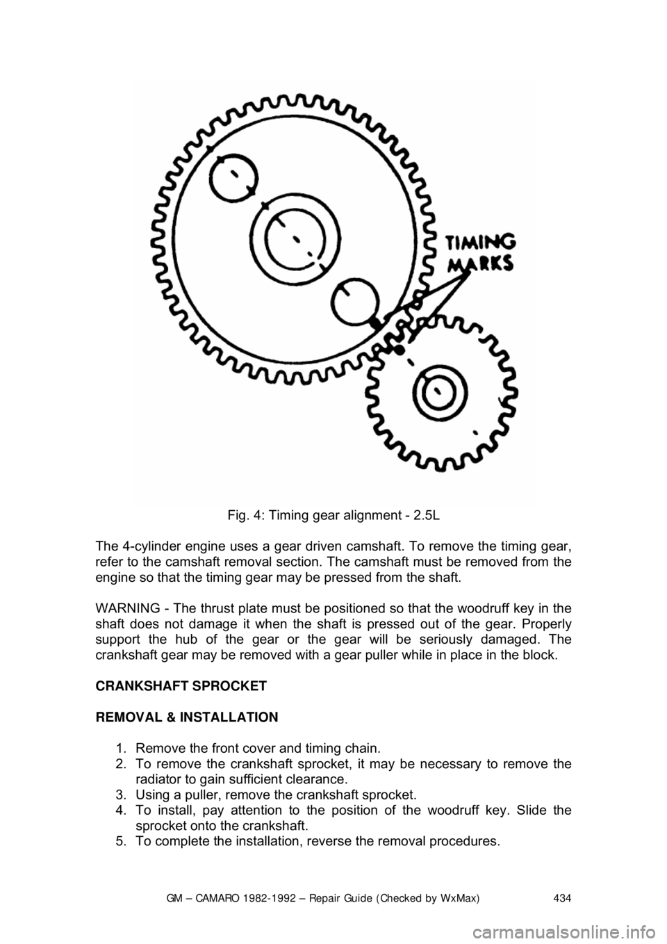
Fig. 4: Timing gear alignment - 2.5L
The 4-cylinder engine uses a gear driven camshaft. To remove the timing gear,
refer to the camshaft removal section. The camshaft must be removed from the
engine so that the timing gear ma y be pressed from the shaft.
WARNING - The thrust plate must be posit ioned so that the woodruff key in the
shaft does not damage it when the shaft is pressed out of the gear. Properly
support the hub of the gear or the gear will be seriously damaged. The
crankshaft gear may be removed with a gear puller while in place in the block.
CRANKSHAFT SPROCKET
REMOVAL & INSTALLATION 1. Remove the front cover and timing chain.
2. To remove the crankshaft sprocket, it may be necessary to remove the
radiator to gain su fficient clearance.
3. Using a puller, remove the crankshaft sprocket.
4. To install, pay attention to the position of the woodruff key. Slide the
sprocket onto the crankshaft.
5. To complete the installation, reverse the removal procedures.
Page 441 of 875

GM – CAMARO 1982-1992 – Repair Guide (Checked by WxMax) 441
2. Remove the fan, driv
e belts and water pump pul ley. Remove the valve
cover. Loosen the rocker arms and pivot them, then remove the
pushrods.
3. Remove the oil pump driveshaft and gear assembly. This is located
under a small plate secured by two bol ts near the oil filter. Remove the
spark plugs.
4. Mark the position of the distribut or rotor, housing, and engine block.
Remove the distributor.
5. Remove the valve lifters. They are located behind the pushrod cover.
6. Remove the timing gear cover.
7. Insert a screwdriver through the holes in the ti ming gear and remove the
2 camshaft thrust plate screws.
8. Pull the camshaft and gear assembly out through the front of the engine
block.
When removing the camshaft, be careful not to damage the camshaft bearings.
9. If the camshaft is to be removed from the timing gear, place the assembly in an arbor press and s eparate. CAUTION When removing the
timing gear from the camshaft, the thrust plate must be positioned so that
the woodruff key does not damage it.
To install: 10. To install the timing gear to the camshaft, press the assembly together
and measure the end clearance. T here should be 0.0015-0.0050 in.
(0.038-0.127mm) between the thrust plate and the camshaft.
If the clearance is less than 0.0015 in. (0 .038mm), replace the spacer ring; if
more than 0.0050 in. (0.127mm), replace the thrust ring.
11. Lubricate the camshaft, bearings, and lifters. Slide the camshaft
assembly into the engine and align the timing marks of the camshaft gear
and crankshaft gear.
12. Complete the installation by reversing the removal procedure.
V6 AND V8 ENGINES 1. Remove the engine from the vehicl e or remove all components from the
front of the engine (radi ator, grille, etc.).
2. Remove the timing gear cover and chain.
3. Mark the distributor rotor, housi ng and engine block, then remove the
distributor. Remove the fuel pump and fuel pump pushrod on carbureted
engines.
4. Remove the intake manifold and valve covers. Loosen the rocker arms
and pivot out of way. Remove the pushrods and valve lifters.
5. Remove the oil pump drive.
6. Slide the camshaft toward the front of the engine (be careful not to
damage the camshaft bearings).
Page 502 of 875

GM – CAMARO 1982-1992 – Repair Guide (Checked by WxMax) 502
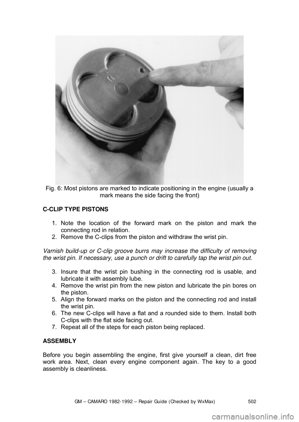
Fig. 6: Most pistons are marked to indica te positioning in the engine (usually a
mark means the side facing the front)
C-CLIP TYPE PISTONS 1. Note the location of the forward mark on the piston and mark the connecting rod in relation.
2. Remove the C-clips from the piston and withdraw the wrist pin.
Varnish build-up or C-clip groove burrs may increase the difficulty of removing
the wrist pin. If necessary, use a punch or drift to carefully tap the wrist pin out.
3. Insure that the wrist pin bushing in the connecting rod is usable, and
lubricate it with assembly lube.
4. Remove the wrist pin from the new piston and lubricate the pin bores on
the piston.
5. Align the forward marks on the pi ston and the connecting rod and install
the wrist pin.
6. The new C-clips will have a flat and a rounded side to them. Install both
C-clips with the flat side facing out.
7. Repeat all of the steps fo r each piston being replaced.
ASSEMBLY
Before you begin assembling the engine, fi rst give yourself a clean, dirt free
work area. Next, clean every engine component again. The key to a good
assembly is cleanliness.
Page 635 of 875

GM – CAMARO 1982-1992 – Repair Guide (Checked by WxMax) 635
FIRING ORDERS
To avoid confusion, remove and tag th
e spark plug wires one at a time, for
replacement.
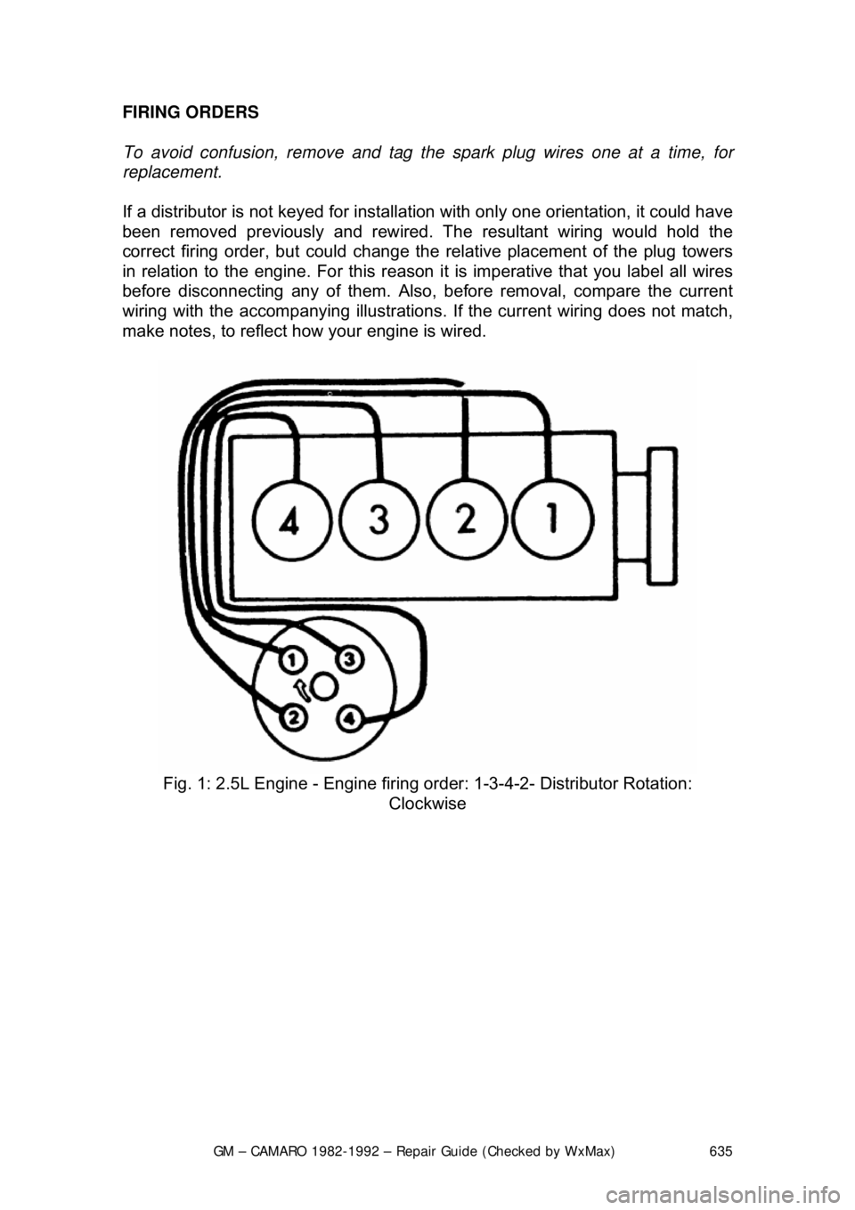
If a distributor is not keyed for installati on with only one orientation, it could have
been removed previously and rewired. Th e resultant wiring would hold the
correct firing order, but could change the relative placement of the plug towers
in relation to the engine. Fo r this reason it is imperative that you label all wires
before disconnecting any of them. Also, before removal, compare the current
wiring with the accompanying i llustrations. If the current wiring does not match,
make notes, to reflect how your engine is wired.
Fig. 1: 2.5L Engine - Engine firing or der: 1-3-4-2- Distributor Rotation:
Clockwise
Page 656 of 875

GM – CAMARO 1982-1992 – Repair Guide (Checked by WxMax) 656
8. Once the timing is set to specific
ation, tighten the distributor hold-down
clamp. Recheck the timing to make su re it did not change while the bolt
was being tightened.
9. Remove the jumper wire from the ALDL connector, if applicable, with the
engine still running. (Usually, if this is performed before the engine is
shut off, no trouble codes will be stored.)
10. Turn the engine OFF, then remove the timing light and tachometer.
Reconnect the number 1 spark plug wire, if disconnected.
11. Attach the 4-wire EST connector at the distributor, or reconnect the Set
Timing connector, if applicable.
12. Check for fault code 42, and clear, if necessary, by disconnecting the
negative battery cable for at least 30 seconds.
To prevent ECM damage, the key must be in the OFF position when
disconnecting or reconnecting battery cables.
1988-90 VEHICLES
When adjusting the timing, refer to the instructions on the emission control
sticker inside the engine compartment. If th e instructions on the label disagree
with the procedure listed below, follo w the instructions on the label.
1. Locate the timing marks on the cran kshaft pulley and the front of the
engine.
2. Clean off the marks and coat them with white paint or chalk, so that they
may be easily seen.
3. Run the engine until it reaches no rmal operating temperature, then shut
off the engine.
4. With the ignition OFF, connect a ta chometer to the distributor, and a
timing light with an inductive pickup lead to the No. 1 spark plug wire.
WARNING - Never pierce a secondary ignition wire in order to connect a timing
light. A pierced wire may lead to engine misfiring and driveability problems.
5. Start the engine. With the engine running and all accessories off, use a
jumper wire to connect diagnostic terminal B and ground terminal A of
the 12-terminal Assembly Line Diagnostic Link (ALDL), located under the
instrument panel.
If jumping the ALDL terminals does not prevent timing advance, the EST
bypass wire will have to be disconnected instead.
6. Aim the timing light at the timing mark. The line on the balancer or pulley
will line up with the timing mark. If a change in timing is necessary,
loosen the hold-down clamp bolt at t he base of the distributor. While
observing the timing mark, rotate the distributor slightly until the line
indicates the correct timing. Use t he timing specification on the emission
control label in the engine compartm ent. If this label is missing or
damaged, refer to the Tune- Up Specifications chart in this Section.
Page 658 of 875

GM – CAMARO 1982-1992 – Repair Guide (Checked by WxMax) 658
Connect the timing light power leads
according to the manufacturer's
instructions.
WARNING - Never pierce a secondary ignition wire in order to connect a timing
light. A pierced wire may lead to engine misfiring and driveability problems.
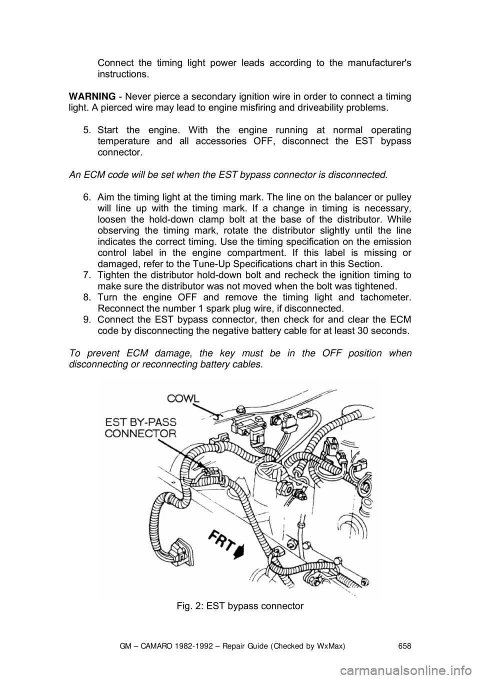
5. Start the engine. With the engine running at normal operating
temperature and all accessories OFF, disconnect the EST bypass
connector.
An ECM code will be set when the EST bypass connector is disconnected.
6. Aim the timing light at the timing mark. The line on the balancer or pulley
will line up with the timing mark. If a change in timing is necessary,
loosen the hold-down clamp bolt at t he base of the distributor. While
observing the timing mark, rotate the distributor slightly until the line
indicates the correct timing. Use t he timing specification on the emission
control label in the engine compartm ent. If this label is missing or
damaged, refer to the Tune- Up Specifications chart in this Section.
7. Tighten the distributor hold-down bolt and recheck the ignition timing to
make sure the distributor was not moved when the bolt was tightened.
8. Turn the engine OFF and remove the timing light and tachometer.
Reconnect the number 1 spark plug wire, if disconnected.
9. Connect the EST bypass connector , then check for and clear the ECM
code by disconnecting the negative battery cable for at least 30 seconds.
To prevent ECM damage, the key must be in the OFF position when
disconnecting or reconnecting battery cables.
Fig. 2: EST bypass connector
Page 698 of 875

GM – CAMARO 1982-1992 – Repair Guide (Checked by WxMax) 698
5. Disconnect and plug hose to canister purge port.
6. Disconnect and plug hose to idle load compensator.
7. Back out idle stop screw
on carburetor 3 turns.
8. Turn air conditioning OFF.
9. Block drive wheels, set parki ng brake, place transmission in P, start and
warm engine to normal operating temperature. Make certain choke is
OPEN .
10. With engine RUNNING place transmission in D and idle load
compensator fully extended (no vacuum applied). Using tool J-29607, or
equivalent, adjust plunger to obtain 650-750 rpm. Locknut on plunger
must be held with a wrench to prevent damage to guide tabs.
11. Measure distance from the locknut to tip of the plunger. This distance
must not exceed 1 in. (25mm). If it does check for low idle condition.
12. Reconnect vacuum hose to idle load compensator and observe idle
speed.
13. Idle speed should be between 425-475 rpm in D.
14. If idle speed is correct no further adjustment is necessary, proceed to the
next step. If idle speed is still incorrect continue as follows:
It may be necessary to remove the idle load compensator from the engine
unless a hex key wrench is m odified to clear obstructions.
a. Stop engine, remove rubber cap from the center outlet tube.
b. Using a 0.90 in. (23mm) hex wrench, insert through open center tube to
engage idle speed adjusting screw.
c. If idle speed was low, turn t he adjusting screw counterclockwise
approximately 1 turn for every 85 rpm low. If idle speed was high turn
screw 1 turn for every 85 rpm high.
15. Disconnect and plug vacuum hose to the idle load compensator.
16. Using a hand pump, apply vacuum to the idle load compensator until fully
retracted.
17. Adjust the idle stop screw on carburetor float bowl to obtain 450 rpm in
D .
18. Place transmission in P and stop engine.
19. Reconnect the idle load compensator.
20. Reconnect all vacuum hoses.
21. Install air cleaner and gasket. Remove wheel blocks.
Page 711 of 875

GM – CAMARO 1982-1992 – Repair Guide (Checked by WxMax) 711
THROTTLE BODY INJECTION SYSTEM
SYSTEM DESCRIPTION
The throttle body injection (TBI) system used on 2.5L (VIN 2) and 5.0L (VIN E)
engines is centrally located
on the intake manifold. Its function is to supply the
correct air/fuel mixture to the engine, as directed by the Engine Control Module
(ECM).
The TBI unit consists of two relatively simple casting assemblies: a throttle body
and a fuel metering assembly. Components include, a pressure regulator, idle
air control valve, fuel injector(s), thro ttle position sensor, fuel inlet and a fuel
return fitting.
The Throttle Body Injection identifi cation number is stamped on the lower
mounting flange located near the TPS. Th e number is in alphabetical code and
should be noted before servicing the unit.
An oxygen sensor in the exhaust syst em functions to provide feedback
information to the ECM as to oxygen content in the exhaust. The ECM then
uses this information to modify fuel de livery to achieve as near as possible an
ideal air/fuel ratio of 14.7 :1. This ratio permits the ca talytic converter to become
more effective in reducing emissions wh ile providing acceptable driveability.
Should you encounter any type of engine performance problem, have a
complete CCC system test performed by a qualified, professional technician. If
the fault lies in the injection system, you can use the following procedures to
remove the TBI unit and replace the defective component(s).
RELIEVING FUEL SYSTEM PRESSURE
1. Disconnect the negative battery cable to prevent fuel discharge if the key
is accidentally turned to the RUN position.
2. Loosen the fuel filler cap to relieve fuel tank pressure and do not tighten
until service has been completed.
3. Fuel system pressure is automatic ally relieved when the engine is turned
OFF. No further action is necessary.
When disconnecting fuel lines, there ma y still be a small amount of fuel
released. Cover the fuel line connection wi th a shop cloth to collect the fuel,
then place the cloth in an approved container.
ELECTRIC FUEL PUMP
REMOVAL & INSTALLATION
The fuel pump is part of t he fuel sender assembly located inside the fuel tank.
1. Release the fuel syst em pressure and disconnec t the negative battery
cable.