1982 CHEVROLET CAMARO check oil
[x] Cancel search: check oilPage 291 of 875

GM – CAMARO 1982-1992 – Repair Guide (Checked by WxMax) 291
6. Remove the console cover.
7. Remove the shifter boot.
8. Remove the shifter mounting bolt
s and remove the shifter assembly.
9. Installation is the reverse of the removal procedure. Adjust the linkage as
detailed earlier.
BACK-UP LIGHT SWITCH
REMOVAL & INSTALLATION 1. Disconnect the negative battery terminal from the battery.
2. At the left-rear of the transmission, the back-up light switch is threaded
into the transmission case. The speed sensor is held in with a separate
bracket. Disconnect the electrical co nnector from the back-up light
switch.
3. Remove the back-up light swit ch from the transmission.
4. To install, reverse the remova l procedures. Coat the threads with
Teflon® tape. Please refer to the to rque chart for specifications. Place
the gear shift lever in the revers e position and check that the back-up
lights work.
EXTENSION HOUSING SEAL
REMOVAL & INSTALLATION
This seal controls transmission oil leakage around the driveshaft. Continued
failure of this seal usually indicates a worn output shaft bushing. If so, there will
be signs of the same wear on the driveshaft where it contacts the seal and
bushing. The seal is available and is fairly simple to install, with the proper tool.
1. Raise and safely support the rear of the vehicle to minimize transmission
oil loss when the driveshaft is removed.
2. Unbolt the driveshaft fr om the differential and center support bearing, if
equipped. Wrap tape around the bearing cu ps to keep them in place on
the universal joint and slide the sh aft out of the transmission.
3. Use an small pry tool to carefully pry out the old seal. Be careful not to
insert the tool too far into the hous ing or the bushing will be damaged.
Page 292 of 875

GM – CAMARO 1982-1992 – Repair Guide (Checked by WxMax) 292
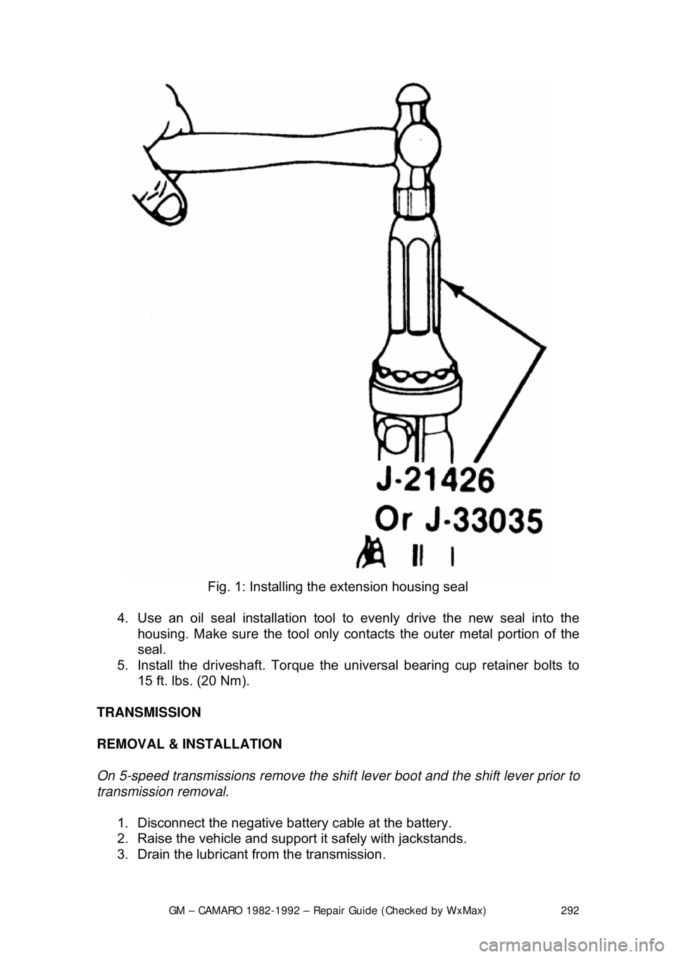
Fig. 1: Installing the extension housing seal
4. Use an oil seal installation tool to evenly drive the new seal into the
housing. Make sure the tool only cont acts the outer metal portion of the
seal.
5. Install the driveshaft. Torque the uni versal bearing cup retainer bolts to
15 ft. lbs. (20 Nm).
TRANSMISSION
REMOVAL & INSTALLATION
On 5-speed transmissions remove the shif t lever boot and the shift lever prior to
transmission removal.
1. Disconnect the negative batte ry cable at the battery.
2. Raise the vehicle and support it safely with jackstands.
3. Drain the lubricant from the transmission.
Page 294 of 875

GM – CAMARO 1982-1992 – Repair Guide (Checked by WxMax) 294
25. Connect the negative battery cable at the battery.
CLUTCH
UNDERSTANDING THE CLUTCH
The purpose of the clutch is to disconnect and connect engine power at the
transmission. A vehicle at rest requires a lot of engine torque to get all that
weight moving. An internal combustion engine does not develop a high starting
torque (unlike steam engines) so it must be allowed to operate without any load
until it builds up enough torque to move the vehicle. To a point, torque
increases with engine rpm. The clutch a llows the engine to build up torque by
physically disconnecting t he engine from the transmission, relieving the engine
of any load or resistance.
The transfer of engine power to the tr ansmission (the load) must be smooth and
gradual; if it weren't, driv e line components would wear out or break quickly.
This gradual power transfer is made possi ble by gradually releasing the clutch
pedal. The clutch disc and pressure plat e are the connecting link between the
engine and transmission. When the clutch pedal is released, the disc and plate
contact each other (the clutch is engag ed) physically joining the engine and
transmission. When the pedal is pushed in, the disc and plate separate (the
clutch is disengaged) disconnecting the engine from the transmission.
Most clutch assemblies consists of t he flywheel, the clutch disc, the clutch
pressure plate, the throw out bearing and fork, the actuating linkage and the
pedal. The flywheel and clutch pressure plate (driving members) are connected
to the engine crankshaft and rotate with it. The clutch disc is located between
the flywheel and pressure plate, and is splined to the transmission shaft. A
driving member is one that is attached to the engine and transfers engine power
to a driven member (clutch disc) on t he transmission shaft. A driving member
(pressure plate) rotates (drives) a driv en member (clutch disc) on contact and,
in so doing, turns the transmission shaft.
There is a circular di aphragm spring within th e pressure plate cover
(transmission side). In a relaxed state (w hen the clutch pedal is fully released)
this spring is convex; that is, it is dished outward toward the transmission.
Pushing in the clutch peda l actuates the attached linkage. Connected to the
other end of this is the throw out fork, which hold the throw out bearing. When
the clutch pedal is depre ssed, the clutch linkage pushes the fork and bearing
forward to contact the diaphragm spring of the pressure plate. The outer edges
of the spring are secured to the pressure plate and are pivoted on rings so that
when the center of the spring is compre ssed by the throw out bearing, the outer
edges bow outward and, by so doing, pu ll the pressure plate in the same
direction - away from the clutch disc. This action se parates the disc from the
plate, disengaging the clutch and allowing the transmission to be shifted into
another gear. A coil type clutch return sp ring attached to the clutch pedal arm
permits full release of the pedal. Releasing the pedal pulls the throw out bearing
away from the diaphragm spring resulting in a reversal of spring position. As
bearing pressure is gradually released from the spring center, the outer edges
Page 309 of 875

GM – CAMARO 1982-1992 – Repair Guide (Checked by WxMax) 309
Fig. 5: Servos, operated by pressure, ar e used to apply or release the bands, to
either hold the ring gear or allow it to rotate
The accumulators are used to cushi on the engagement of the servos. The
transmission fluid must pass through the ac cumulator on the way to the servo.
The accumulator housing contains a thin piston which is sprung away from the
discharge passage of the accumulato r. When fluid passes through the
accumulator on the way to the servo, it must move the piston against spring
pressure, and this action smooths out the action of the servo.
HYDRAULIC CONTROL SYSTEM
The hydraulic pressure used to operat e the servos comes from the main
transmission oil pump. This fluid is channel ed to the various servos through the
shift valves. There is generally a manual shift valve which is operated by the
transmission selector lever and an automat ic shift valve for each automatic
upshift the transmission provides.
Many new transmissions are electroni cally controlled. On these models,
electrical solenoids are used to better control the hydraulic fluid. Usually, the
solenoids are regulated by an electronic control module.
There are two pressures which affect t he operation of these valves. One is the
governor pressure which is effected by vehicle speed. The other is the
modulator pressure which is effected by intake manifold vacuum or throttle
position. Governor pressure rises wit h an increase in vehicle speed, and
Page 317 of 875

GM – CAMARO 1982-1992 – Repair Guide (Checked by WxMax) 317
1. Place the shifter lever in the
P position. Remove the negative battery
cable.
2. Turn the key to RUN.
3. Remove the left side instrument panel sound insulator and kick panels.
4. Remove the floor console.
5. Remove the cable nut and clip. Remove the cable from the bracket, move the button to the UP position and unsnap the cable end from the
lever lock pin.
6. Lower the steering column. Remove the cable clips.
To install: 7. Place the shifter lever into the P position and the ignition key to the RUN
position.
8. After installing the cable ends, push the cable connector nose toward th\
e connector as far as possible and push down the lock button.
9. Complete the installation by reversing the removal procedure.
EXTENSION HOUSING SEAL (IN VEHICLE)
REMOVAL & INSTALLATION
This seal controls transmission oil leakage around the driveshaft. Continued
failure of this seal usually indicates a worn output shaft bushing. If so, there will
be signs of the same wear on the driveshaft where it contacts the seal and
bushing. The seal is available and is fairly simple to install, with the proper tool.
1. Raise and safely support rear of t he vehicle to minimize transmission oil
loss when the driveshaft is removed.
2. Unbolt the driveshaft fr om the differential and center support bearing, if
equipped. Wrap tape around the bearing cu ps to keep them in place on
the universal joint and slide the sh aft out of the transmission.
3. Use a small pry tool to carefully pr y out the old seal. Be careful not to
insert the tool too far into the hous ing or the bushing will be damaged.
4. Use an oil seal installation tool to evenly drive the new seal into the
housing. Make sure the tool only cont acts the outer metal portion of the
seal.
5. Install the driveshaft. Torque the uni versal bearing cup retainer bolts to
15 ft. lbs. (20 Nm). Recheck fluid level.
TRANSMISSION
REMOVAL & INSTALLATION 1. Disconnect the negative batte ry cable at the battery.
2. Remove the air cleaner assembly.
3. Disconnect the throttle valve (TV) control cable at the carburetor.
Page 318 of 875

GM – CAMARO 1982-1992 – Repair Guide (Checked by WxMax) 318
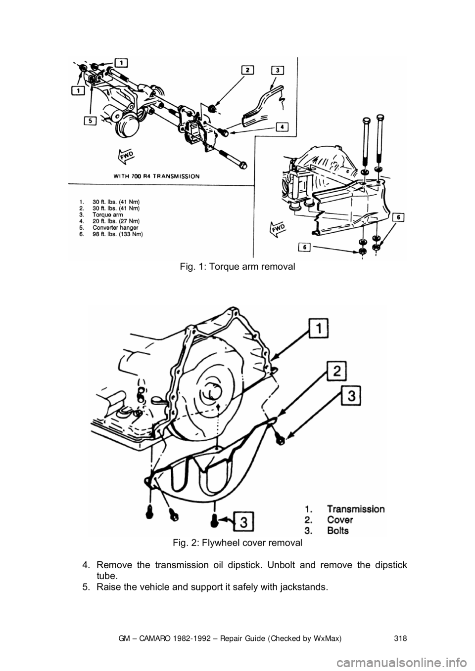
Fig. 1: Torque arm removal
Fig. 2: Flywheel cover removal
4. Remove the transmission oil dipsti ck. Unbolt and remove the dipstick
tube.
5. Raise the vehicle and support it safely with jackstands.
Page 321 of 875

GM – CAMARO 1982-1992 – Repair Guide (Checked by WxMax) 321
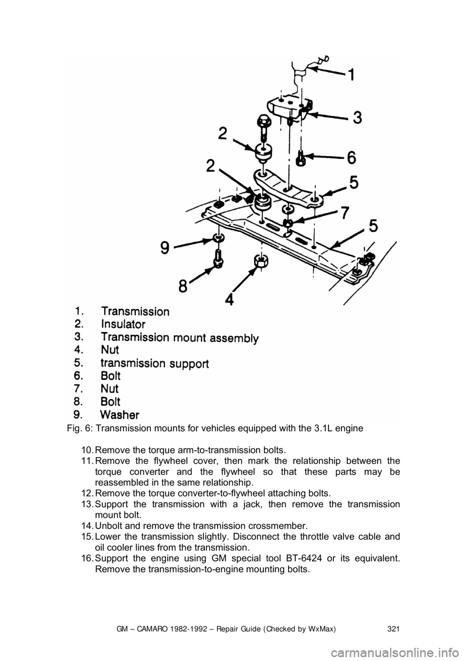
Fig. 6: Transmission mounts for vehi cles equipped with the 3.1L engine
10. Remove the torque arm-to-transmission bolts.
11. Remove the flywheel cover, t hen mark the relationship between the
torque converter and the flywheel so that these parts may be
reassembled in the same relationship.
12. Remove the torque converter-t o-flywheel attaching bolts.
13. Support the transmission with a ja ck, then remove the transmission
mount bolt.
14. Unbolt and remove the transmission crossmember.
15. Lower the transmission slightly. Disco nnect the throttle valve cable and
oil cooler lines from the transmission.
16. Support the engine using GM specia l tool BT-6424 or its equivalent.
Remove the transmission- to-engine mounting bolts.
Page 322 of 875

GM – CAMARO 1982-1992 – Repair Guide (Checked by WxMax) 322
CAUTION - The transmission must be secu red to the transmission jack
17. Remove the transmission from the vehicle. Be careful not to damage the oil cooler lines, throttle valve cable, or the shift control cable. Also, keep
the rear of the transmissi on lower than the front to avoid the possibility of
the torque converter disengagi ng from the transmission.
To install: 18. Position the transmission and converter into place.
19. Install the transmission -to-engine mounting bolts.
20. Connect the throttle valve cable and oil cooler lines to the transmissio\
n.
21. Install the transmission cro ssmember and secure with bolts.
22. Install the transmission mount bolt.
23. Matchmark the torque converter-to-f lywheel. Install the torque converter-
to-flywheel attaching bolts.
Before installing the converter-to-flywheel bolts, be sure that the weld nuts on
the converter are flush with the flywheel, and that the converter rotates freely by
hand in this position.
24. Install the flywheel cover.
25. Install the torque arm-to-transmission bolts.
26. Connect the speedometer cable, el ectrical connectors and the shift
control cable from the transmission.
27. Connect the catalytic converter s upport bracket at the transmission.
28. Align the matchmark m ade earlier, then install the driveshaft to the axle
pinion. Bolt the universal joint straps to the pinion flange.
29. Lower the vehicle.
30. Install the dipstick tube using a ne w dipstick tube O-ring and secure with
the bolt. Install the tran smission oil dipstick.
31. Connect the throttle valve (TV) c ontrol cable at the carburetor.
32. Install the air cleaner assembly.
33. Connect the negative battery cable at the battery.
DRIVELINE
DRIVESHAFT AND U-JOINTS
The U-joint is secured to the yoke in one of two ways. Dana and Cleveland
shafts use a conventional snapring to ho ld each bearing cup in the yoke. The
snapring fits into a groove located in eac h yoke end just on top of each bearing
cup. The Saginaw design shaft secures its U-joints in another way. Nylon
material is injected through a small hole in the yoke and flows along a circular
groove between the U-joint and the yoke , creating a synthetic snapring.
Disassembly of the Saginaw U-joint requi res the joint to be pressed from the
yoke. This results in damage to the be aring cups and destruction of the nylon
rings.