1980 SKODA 120 LSE oil
[x] Cancel search: oilPage 127 of 238
Shr
C
cle,
the
1
fittr
bor
(Im(
2
wit
woI
pisl
wor
the loc<(11,
3.
obo (M(
I nst
rod
the
oil' into
4.
witt
Con
prot
Inod
On f(
Inodr
oll c(
Excer
on c(
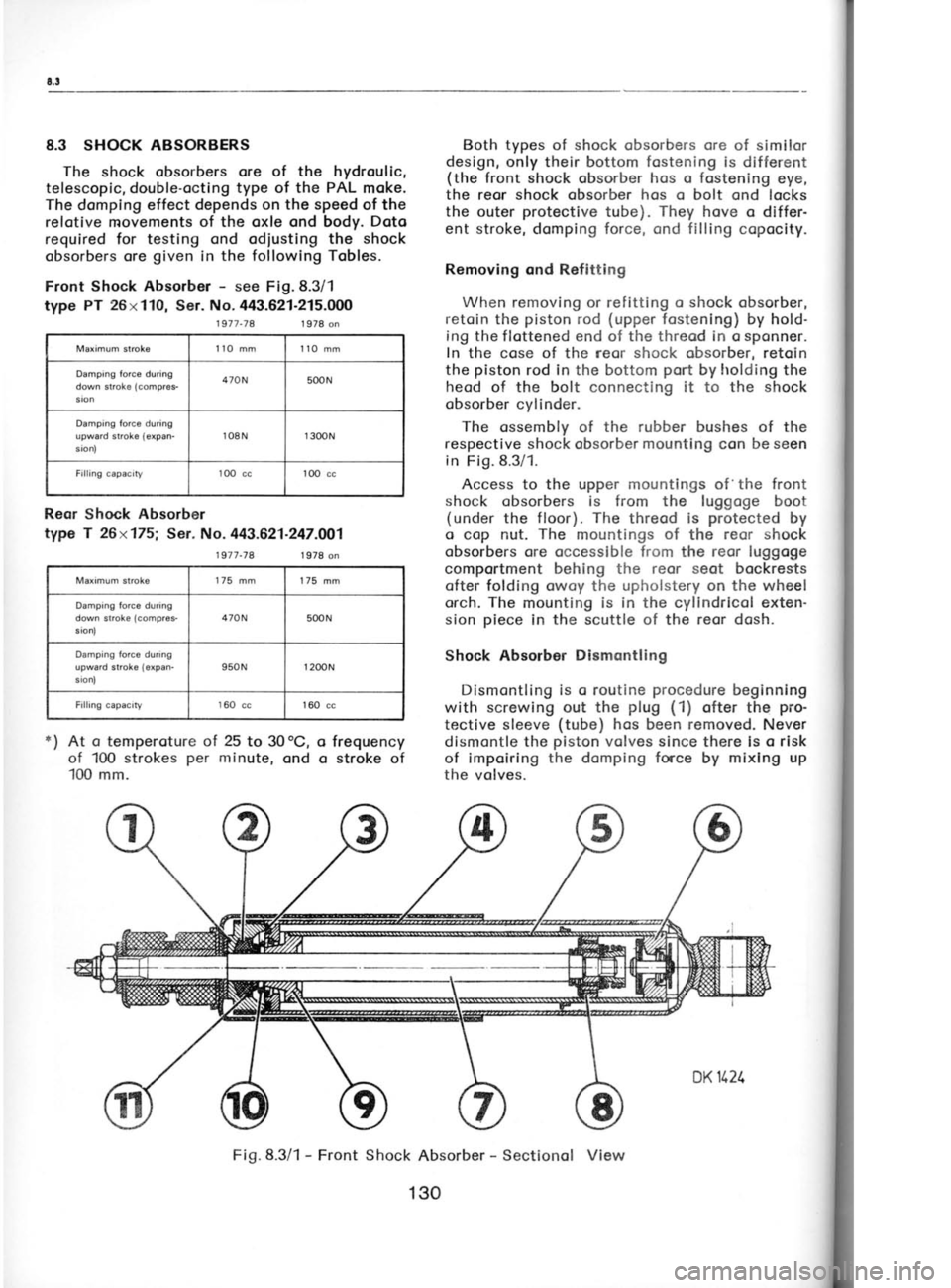
8.3 SHOCK ABSORBERS
The shock obsorbers ore of
the hydroulic,
telescopic, double-octing type of the PAL
moke.
The domping effect depends on the speed
of the
relotive movements of the oxle ond body. Doto
required for testing ond odiusting the shock
obsorbers ore given
in the following Tobles.
Front Shock Absorber -
see Fig.8.3/1
type PT 26x110,
Ser. No.443.621-215.000
1977-74 1 978 on
Maximum stroks llO mm 110 mm
Damping torce during
down stroke (compr€s-
sion 470N
500N
Damping force
during
upward stroke (expan-
sion) loSN
1
300N
Filling capacity lOO cc1OO
cc
Reor Shock Absorber
type T 26x175; Ser. No. 443.621.247.OO1
1977-78 1 978 on Both
types of shock obsorbers ore of similor
design, only their bottom fostening
is different
(the front shock obsorber hos o fostening eye,
the reor shock obsorber hos
o bolt ond locks
the outer protective
tube). They hove
o differ-
ent stroke, domping force, ond filling
copocity.
Removing ond Refitting When removing or refitting o shock
obsorber,
retoin the piston
rod (upper
fostening) by hold-
ing the flottened end of the threod in o sponner.
In the cose of
the reor shock cbsorber, retoin
the piston
rod in the bottom port
by holding the
heod of the bolt connecting it to the shock
obsorber cylinder.
The ossembly of the rubber bushes of the
respective shock obsorber mounting
con be seen
in Fig.8.3/1.
Access to the upper mountings of 'the
front
shock obsorbers is from the luggoge boot
(under the floor). The
threod is protected
by
o cop nut. The
mountings of
the reor shock
obsorbers ore occessible from the reor luggoge
comportment behing the reor seot bockrests ofter folding owoy the upholstery on the wheel
orch. The mounting is in the cyllndricol exten-
sion piece
in the scuttle
of the reor dosh.
Shock Absorbor Dismcntling
Dismontling is o routine procedure
beginning
with screwing out the plug
(1)
ofter the pro-
tective sleeve (tube)
hos been removed. Never
dismontle the piston
volves since there is o risk
of impoiring the domping force
by mixlng up
the volves.
o
o
*)
At o
temperoture ol 25
to 30oC,
of 100 strokes per
minute, ond
100 mm. frequency
stroke of
Fig.8.3/1 -
Front Shock Absorber -
Sectionol View
Maximum stroke
175 mm
175 mm
Damping force during
down stroke (compres-
ston, 470N
500N
Damping force during
upward stroke {expan-
sronl 950N
r
200N
Filling capacity 160
cc 160 cc
130
Page 129 of 238
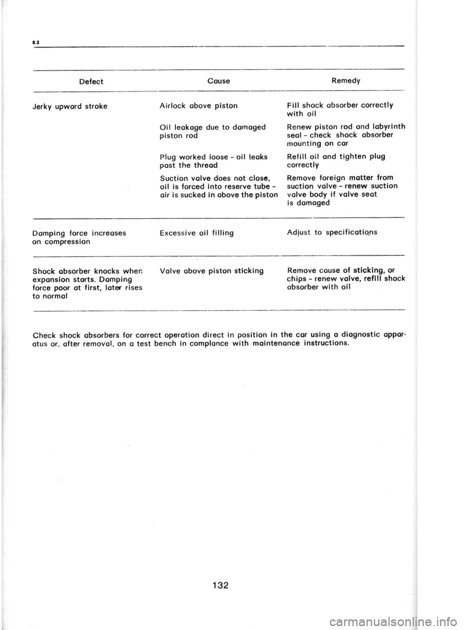
Defect
Remedy
Jerky upword stroke Airlock
obove plston
Oil leokoge due to domoged
piston rod
Plug worked loose -
oil leoks
post the threod
Suction volve does not closc,
oil is forced Into reserve
tube -
oir is sucked
in obove
the plston Flll
shock obsorber
correctly
wlth oil
Renew piston
rod ond lobyrinth
seol -
check shock
obsorber
mountlng on cor
Reflll oil ond tighten plug
correctly
Remove foreign motter
from
suction volve -
renew suction
volve body lf volve seot
is domoged
Domping force increoses
on compression Excessive
oil filling Adiust to specificotio.ns
Shock obsorber knocks when
exponslon storts. Domping
force poor
ot first. loter rises
to normol Volve obove
piston
sticking Remove couse of
stlcklng, or
chlps -
renew volve, reflll shock
obsorber with oll
Check shock obsorbers for correct operotlon direct in position
in the cor uslng o diognostic
oppor'
otus or, ofter removol, on o
test bench in
complonce with molntenonce
instructlons.
132
Page 140 of 238
![SKODA 120 LSE 1980 Workshop Manual 9Vl
e6pe uu eql ol pellll
slq6teM
6ulcuo1oq lo suoeu
Aq pecuoloq
AllocgtuouAp
eq plnoqs
e:Al aqt qglnn
alegduoc
loaqM aql
Pa]]!l
ueaq soq a.rA1 r*eu lo pe.rloda.r
o renauaqM
lsnu D
SKODA 120 LSE 1980 Workshop Manual 9Vl
e6pe uu eql ol pellll
slq6teM
6ulcuo1oq lo suoeu
Aq pecuoloq
AllocgtuouAp
eq plnoqs
e:Al aqt qglnn
alegduoc
loaqM aql
Pa]]!l
ueaq soq a.rA1 r*eu lo pe.rloda.r
o renauaqM
lsnu D](/manual-img/3/57425/w960_57425-139.png)
9Vl
'e6pe uu eql ol pellll
slq6teM
6ulcuo1oq lo suoeu
Aq pecuoloq
AllocgtuouAp
eq plnoqs
e:Al aqt qglnn
alegduoc
loaqM aql
'Pa]]!l
ueaq soq a.rA1 r*eu lo pe.rloda.r
o renauaqM
lsnu D
sq 6u1cuo;oq
leeq1 'roam
arnloueld
:1aq1 6ulsnDc puo
syod
luauodruoc .loa6 6u!
-resls puD elxo eq1 lgq61q 6u1sse:1s sec.rol
;o6n1
-lllueo Alopuocas ol esu sen16
sgeaqmeql
lo ses
-sour pecuoloqun
lo uo!lDloJ
pldo.r 'uo;g!ppD
ul
'6ug.ree1s asgcald .rlodur snql puo 'JotueJl
leaqM
6u1rea1s puD uollDJq!^
esnDc 'elqqorrt
ol puol
sleeqM pecuoloqun 'agqrssod
so Algce;rad so
pecuolDq oq lsnur sa.rA1
uo-pellll qllM
sleaqM
eql 'rDc
eql lo salllado.rd
6ur.ree1s poo6
.ro3
9NtCNVlV8 13fH/v t'ot
'las aql +o rapuleutaj
aql ol qcleul
e sl
lr ornsue
leaqm e 6urce;de.r
1g 'A;uo
sa:[ ;erpe.r as1
'alxe ouo uo adAl oules aql
;o satAl esn Alug
'sp!s euo uo reloe:6
s! JDaM atAl
;r 'Ds.!en
aJtA
puo Joqlo eql o]
apts auo eql uolt pauo111soda.r
Aluo 1nq pa6uoqc.ralur
aq
lou plnoqs
slaeqM €r1l
'JDc D uo sa.rl1 1o sadAl orrrrl
6r-rrurquloc uaqM
sf aaqg
;o a6uoqcralut
-
LIZ'OL '6tJ 'JDC
eql uo
p_esn s! sel{1
1o adAl
alBurs o
;r lluo
$q'Lft.OL
'69 u!_umoqs uo.r6o1p
oql ol 6urp.rocco sloeqM
eql e6uDqoralul 'qo!
ecuDualu!otu o ,{11cri1s
lou sl slqr
q6noqllD 'sleaqM
eql a6uoqcralu!
ol alqostApD s!
l! 'lonbeun
st rDeM atll aq1 y;
sleetln1 1o a6uoqclelul
'spjopuDls Puo suotlopuatuuoceJ
alqocr;ddo A11oco1 eql qllM
acuolldruoc u! ol
pereqpo eq plnoqs ''rle
'(sa:n6r1)
u.ra11od poa.r1
eql lo fq6laq u.rnt!!ultu
eql 'pDarl
;o edll u"ro1
-!un D 'elduoxa
lo; '6ugu:ecuoc
selnl Jeql6
'elxo JDet eql uo s; eco;d .r1aq1 ,sa.rll
lDlpDJ orvrl
6u1sn ueq7y1'sa.rll
lo edlt
euo slorvr;o
aq lltM gJaql
slxD ouo uo
1oq1 igauou ,pan:asqo
eq lsntu uolllpuo3
suo 'sleeq/t^
aql llD uo
sa:41
1o ed{1 euos
eql esn o} a1q;ssod
lou s!
il }l
e6uoqc erAl
sSu^t Jo
SoNVHCUfINI ONV 39NVHC
Z'OL
'(71uc761 e'0 ol
Z'0) odl
OC ol
0Z louorltppD
Iq pes!Di
eq uoc seJnssa.rd a.rA1 'sAottlolor.u
uo 6u;n1.rp usr1m Josrvr e:41 acnpa: o1 'ssel
-eqnl Jo paqnl 'sarA1
ploc |o sslnssaJd
uollo;1ur
eql aJD oA!s!cep
1nq 'es1.r
o1 a:nssa:d aql sasnD:)
6ur;1enor1 6u1.rnp a.rA1 aqt
lo dn
6urloag
(suc761 6'L) odl
061
(sruc761 U'L) odl
6SL JDEJ
luoJl
:se:41 lqd-;orpo.r puo
sarAl l1d-sso.rc uoluJaqC
(ploc) sernssar4 erAl
'esn
Aenruolor.u papualxa pue
speol Aneaq lorr ed)
Ot
ol OZ Aq alnssard arA]
asea:cur a^oqe (V)
tdecxa
lsd gziozed>4
ssataqnl
0t x
991
lsd gz/ozed>t
ssataqnl
et x
ggt
tsd gz/ozed>l
aqnl
et x
99t
lsd gz/ozed
ssstaqnl
e I x
99 i
lsd gz/ozed>
ssataqnt
t I x
99 |
lsd ot/qzed:N aqnl
tt x
99 I
reau e/nssord sseloqnl
FuuJ erAI
/eqn1 ozrs
ei^_l Aoile
0t x
f2,19
Aoile0!xa 9
taals e I x
f%t
t.als €t x
f%g
laals et x
f%t uo
816t
taals t! x
t'%t 816!-116t (V)
ozfs leeq^l )ee)\
t'0r-t'0t AINO
y1'1
uorldr.rcseq
leetuqcal
Page 141 of 238
r 0.3-t0,5
Ihe permissible
out-of-bolonce must not ex-
ceed 50 grommes
on the rim rodius. Every new
tyre is provided
with o coloured dot on its side,
indicoting its lightest point.
Fit the tyre olwoys
with this dot focing
the tube volve.
ln this
position, the volve octs os on odditionol weight
compensoting the wheel overoll unbolonce to
o consideroble extent.
lf dynomic boloncing of the wheel is not
possible, bolonce the wheel stoticolly with the
greotest possible qssuroc|.
Boloncing weights
of 30, 50, 75,
ond 100 grommes
ore ovoiloble.
10.4 TUBED TYRES
For mounting,
dismounting,
ond repoirs of
conventionol tyres with inner tubes (for
por-
ticulors, see the preceding
Chopters), the usuol
procedures ore opplicoble. The permissible run-
out (untrue
running)
of the rim is the some os
for tubeless tyres (Chopter
10.5).
10.5 TUBELESS TYRES
The oir-tight seoling of these tyres requires
more core ond o different hondling thon thot of
the tyres with inner
tubes.
Preporotlon of Rirrr
13elore mounting the tyre, inspect the rim for
ony technicol defects. The points
to be checked
ore the rim shoulder ond the moting foce for
the tyre beods,
in oddition to the overoll con-
dition of the rim. lf ony defects ore found, the
rim must be reconditioned.
A sotisfoctory rim
nrust comply with the following conditions:
o) The
rim shoulder ond the tyre volve hole
must not be distorted;
there must be no
shcrp edges or protrusions
likely to domoge
the tyre beod. Minor unevennesses
con be
hornmered flot ond smoothed
with o file.
The moximum eccentric running
of the rim
side must not exceed 1.5 mm.
b) The moting surfoces
must be obsolutely
cleon (free
from stuck-on rubber, rust,
etc.).
Cleon them with emery poper
or o wire brush
ond coot them with point.
lnstolling of Tyre
Volve
Cleon the rim with o dry rog. Push
the rubber
volve into
the hole in the rim
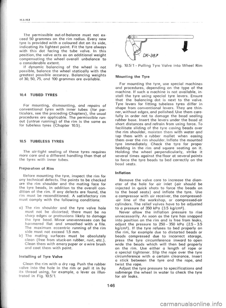
or pull
it in
by
its threod using, for exomple,
o lever
os illus-
troted in Fig. 10.5/1. Fig. 10.5/1
-
Pulling Tyre Volve
irrto Wheel Rim
Mounting the Tyre
For mounting the tyre, use speciol mochines
ond procedures,
depending on the type of the
nrochine. lf such o mochine is not ovoiloble, in-
stoll the tyre using speciol tyre levers.
Ensure
thot the boloncing dot is next to the volve.
Tyre leverrs for fitting tubeless tyres
differ in
shope from conventionol levers. They
ore thin-
ner, without edges, ond polished.
Use them core-
fully in order not to domoge the
beod seoling
rubber bose. Insert the levers
under the beod
ot
short distonces ond refroin from using force. To
focilitote sliding of the tyre cosing beods over
the rim shoulder, moisten them with woter ond
top them with o rubber
mollet when eosing
them over the rim shoulder. Inflote
the mounted
tyre immediotely. Check the tyre for propei'
bedding in the rim ond
squore seoting
on it.
Holding the wheel perpendiculorly,
strike it
severol times ogoinst the f loor ot severol points
to force the tyre beods
to bed
correctly on the
bcad seots.
lnf lotion
Remove the volve
core to increose
the diom-
eter of the hole for oir inlet (oir
should be
iniected in quick
shots to force
the beods
on
to the beod seots) ond inflote the tyre. Use
o compressor with oir receiver, the
compressed-
.oir line of the
workshop, or
compressed-oirr
cylinders. The relief volves hove to be odiusted
to o pressure
of 350 kPo (3.5
kg/cmz).
Never ollow the inflotion pressure
to rise
unnecessorily. As soon os the tyre hos snopped
into position
on the rim
ond is free from leoks,
odiust the pressure
to 250 -
350 kPo (2.5 -
3.5
kg/cmz). lf the tyre refuses to
bed properly
on
the rim,
for exomple due to distorted beods or
beods compressed due to incorrect storoge,
press the tyre circumference inword to open
wide the beods which will then bed properly
on the rim. Use either o length of
rope or
o speciol tightener. Slip the rope over the
tyre
circumference with o certoin cleoronce, insert
o stick
between the tyre ond the rope, ond
twist the rope.
Adiust the tyre pressure
to specif
icotions ond
submerge the wheel in woter to check the
tyre
for oir leoks.
146
Page 148 of 238
c
I'
b
o ir
fi$r
++$$
$$fr0$0$$$$$. $'$j,$,0$$$$+$
t'$'i$$0',$$$$ 0 0
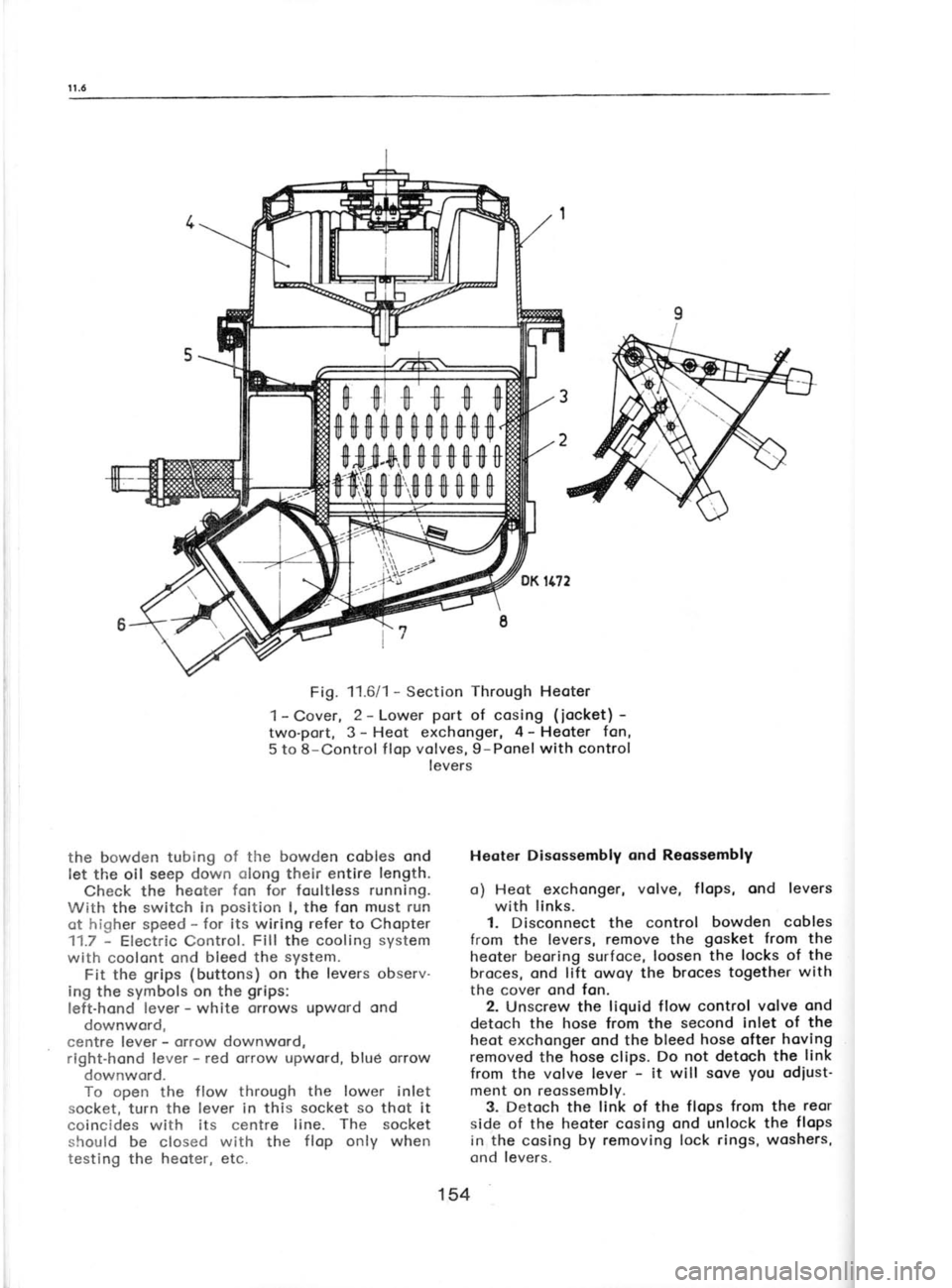
Fig. 11.6/1 -
Section Through
Heoter
1- Cover, 2 -
Lower port
of cosing (iocket) -
two-port, 3- Heot exchonger, 4-
Heoter fan,
5 to 8-Control f lop volves, 9-Ponel with control
levers
the bowden tubing of the
bowden cobles ond
let the oil seep down olong
their entire length.
Check the heoter fon for foultless running.
With the switch in position
I, the fon must run
ot higher speed -
for its wiring refer
to Chopter
11.7 -
Electric Control. Fill
the cooling system
with coolont ond bleed the system.
Fit the grips (buttons)
on the levers observ-
ing the symbols on the grips:
left-hond lever -
white orrows upword ond
downword,
centre lever -
orrow downword,
right-hond lever -
red orrow upword, blud orrow
downword.
To open the flow through the lower inlet
socket, turn the lever in this socket so
thot it
coincides with its centre line. The socket
should be closed with
the flop only
when
testing the heoter, etc. Heoter Disossembly
ond Reossembly
o) Heot exchonger, volve,
flops, ond levers
with links.
1. Disconnect the control bowden
cobles
from the levers, remove the gosket
from the
heoter beoring surfoce, loosen the
locks of the
broces, ond lift owoy the broces together
with
the cover ond fon.
2. Unscrew the liquid flow control volve ond
detoch the hose from
the second
inlet of the
heot exchonger ond the bleed hose ofter hoving
removed the hose
clips. Do not detoch
the link
from the volve lever -
it will sove you
odiust'
ment on reossembly.
3. Detoch the link of the flops from the reor
side of the heoter cosing ond unlock the flops
in the cosing by removing lock rings, woshers,
ond levers.
154
Page 150 of 238
1 1.8-11.10
11.8 HEATER
CONNECTING LINE
The line is o
combinotion of steel pipes
ond
rubber hoses. All connections must be tightened
with clips of
the strip
type (see
Fig. 11.411) or
the wire type (bleed
hose). Toke
core not to
overtighten the clips of the lotter type os there
is o risk of domoging the rubber.
The hose from the pipe
of the thermostot
body on the engine is routed to the heoter
through the f loor tunnel, the return bronch
possing ogoin through the tunnel to the pipe
of
the pump.
Arronge the hoses olong the sides
of
the floor tunnel so
thot they do not touch other
ports in the tunnel.
For detoiled informotion obout the routing of
the hoses refer to
Chopter 12.7.
11.9 otl COOLER
The oil cooler is stondord
equipment of
Skodo
120 LS models. lts construction resembles thot
of the rodiotor. lt is
instolled in the
engine
comportment (boy)
ond ottoched to the right-
-hond engine guord.
Speciol pressure
hoses
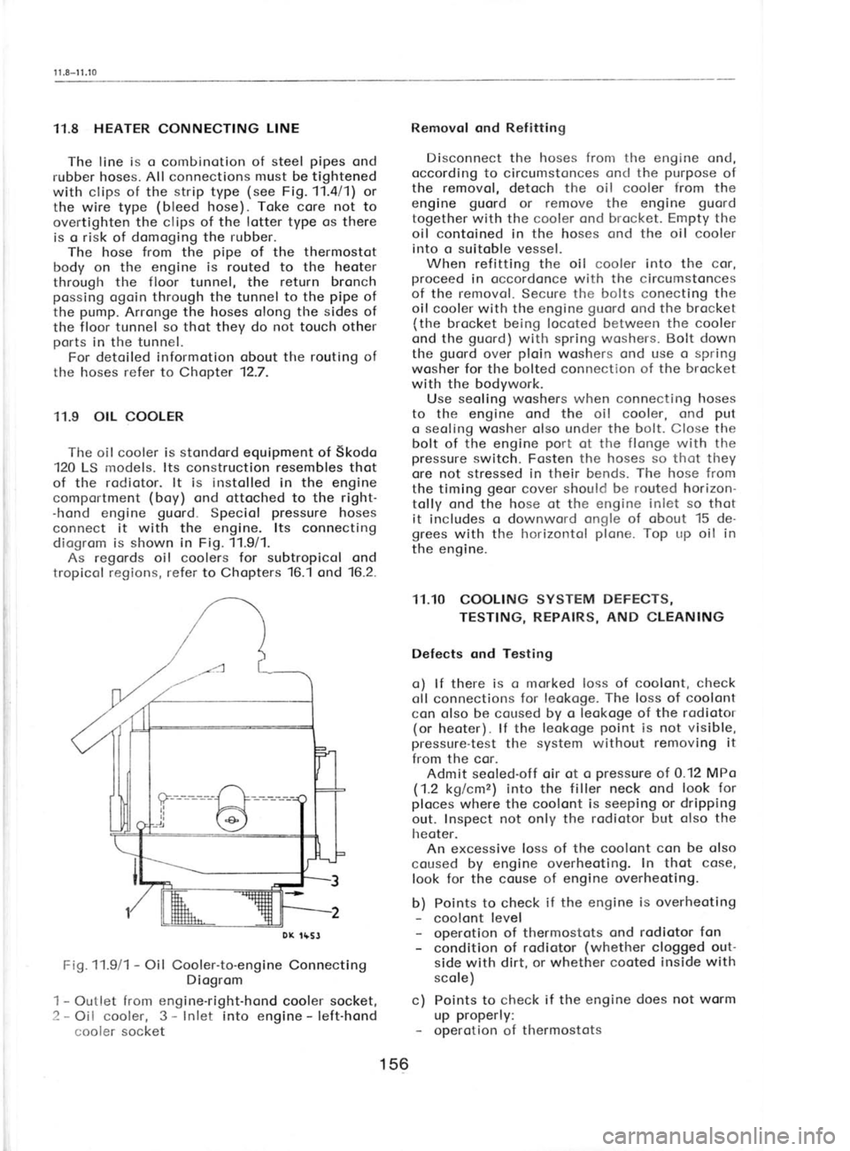
connect it with the engine. lts connecting
diogrom is shown in
Fig. 11.911.
As regords oil coolers for subtropicol ond
tropicol regions, refer to
Chopters 16.1
ond '16.2.
Fi9.11.9/1 -
Oil Cooler-to-engine Connecting
Diogrom
1 -
Outlet from engine-right-hond cooler socket,
2 -
Oil cooler, 3 -
Inlet into engine -
left-hond
cooler socket Removol ond
Refitting
Disconnect the hoses fronr the engine ond,
occording to circumstonces ond the purpose
of
the removol, detoch the oil cooler from
the
engine guord
or remove the engine guord
together with the cooler ond brocket. Empty the
oil contoined in the hoses ond the oil cooler
into o suitoble vessel. When refitting the oil
cooler into the cor,
proceed in occordonce with the circumstonces
of the removol. Secure the bolts conecting the
oil cooler with the engine guord
ond the brocket
(the brocket being locoted between the cooler
ond the guord)
with spring
woshers. Bolt down
the guord
over ploin
woshers ond use o spring
wosher for the bolted connection of the brocket
with the bodywork.
Use seoling
woshers when connecting hoses
to the engine ond the oil cooler, ond put
o seoling wosher olso under the bolt. Close the
bolt of the engine port
ot the flonge with the
pressure switch. Fosten the hoses so thot they
ore not stressed in their bends. The
hose from
the timing geor
cover should be routed horizon-
tolly ond the hose ot
the engine inlet so thot
it includes o downword ongle of obout 15 de-
grees with the horizontol plone. Top up
oil in
the engine.
11.10 COOLING SYSTEM DEFECTS,
TESTING, REPAIRS, AND
CLEANING
Defects ond Testing o) lf there is o marked loss of coolont, check
oll connections for leokoge. The
loss of coolont
con olso be coused by o leokoge of the rodiotor
(or heoter). lf the leokoge point
is not visible,
pressure-test the system without removing it
from the cor. Admit seoled-off oir ot o pressure
of 0.12 MPo
(1.2 kglcmz) into the filler neck ond look for
ploces where the coolont is seeping or dripping
out. Inspect not only the rodiotor but olso the
lreoter. An excessive loss of the coolont con be olso
coused by engine overheoting. In thot cose,
look for the couse of engine overheoting.
b) Points to check if the engine
is overheoting
- coolont level
- operotion of thermostots ond rodiotor fon
- condition of rodiotor (whether
clogged out-
side with dirt, or whether cooted inside with
scole)
c) Points to check if the engine does not worm
up properly:
- operotion of thermostots
DX
tfSJ
156
Page 154 of 238
r 2.1-t 2.3
I
I I
I
Dissssembly
ond
Reossembly of Pedols
This is usuolly not necessory. The pedols
con
be disossembled ofter removing the oxiol screw
in the pedol
pin
ond slipping off the return
spring. Do not remove the switches if it is not
obsolutely necessory -
see odiustment. On re-
ossembly, lubricote
the pedol
bush with lubri-
coting greose
of the some brond os used for the
steering linkoge -
see Chopter 7.5, por.3.
Pedol Free Trovel
Adiustment
Adjust the free
trovel of pedols
ossembled
with moster cylinders so thot the pedol piston
rod hos o
cleoronce of 0.5
to 1mm
when beoring
ogoinst the piston
heods of the
moster cylin-
ders. The free trovel of the pedol pod
should be
from 3 to 5 mm. lt
con be odiusted by rototing
the eccentric pin
on the pedol
brocket -
see
Fi9.12.111.
For the odjustment of the broke pedol
with
broke booster ond/or levelling of the broke
pedol with the
clutch pedol,
see Chopter 9.6 -
Ad justment.
Adiustment of Switches The switches con be
moved in
the ellipticol
holes of the brocket ofter loosening the fosten-
ing copscrews with ploin
woshers under their
heods. A pocking piece
should be slipped
under
the switch of the broke pedol
trovel worning
light ond the powl
of the switch pin
should be
held down under the fostening copscrew.
Ad just
the stop-light switch
so thot it
switches on the stop lights ot o pedol
trovel
of 10 to 15 mm meosured on the centre of the
pedol pod.
Adiust the pedol
trovel signolling switch so
thot the pushed-in
side push-button
pin
is
re,ecsed ot o pedol
trovel of 100 to 110 mm
mecsured on
the centre of the pedol
pod.
Press
the push
button into
the switch ofter hoving
completed the
odiustment.
12.2 ACCELERATOR PEDAL AND CABLE
The occelerotor pedol
forms o unit with its
self-lubricoting beoring ond the lever.
lt is
bolted to the f
loor tunnel. A coble possing
through the tunnel is ottoched to the pedol
lever ond the reloy
lever on the engine by
meons of clomps- The coble is protected
by
o Bowden tubing.
Pedol Removing ond Refitting
1. Loosen the clomp holding the coble on the
engine-mounted reloy lever. 2.
Remove the copscrews holding
down the
becrring with the pedol,
depress lightly the
pedol, ond lift it out of the f loor
tunnel together
with the beoring. 3. Disconnect the pedol
from the coble ofter
ioosening the clomp.
Removol ond Refitting of Bowden Tubing
ond Cqble
The Bowden tubing is
fostened to
the brocket
irr the floor tunnel by
meons of circlips. After
their removol, pull
the Bowden tubing inside
the cor. On ref
itting the tubing, lubricote it with
o low-viscosity oil (of
the SAE 20
closs). lt hos
been lubricoted with greose
in the foctory.
Fit
the clonrps so thot their longer ports (from
the
screw to their end) ore on the side of the
I evers.
Accelerotor Coble Adiustment
Adjust the coble so
thot it is not
excessively
tensioned or too slock. Loosen the clomps on
the engine side of the coble, move slightly
the
clomp toword the reloy lever,
ond tighten the
screws of the clomp.
12.3 GEAR SHIFT LEVER
AND LINKAGE
The geor shift mechonism consists of two
units: the geor
lever with its housing ond oc-
cessories, ond the geor
shifter rod
ond the
shifter lirrk with joint
(ot the georbox)
for
domping the vibrotion of the power
pock
tronsnritted to the geor
lever.
Removing Geor Lever
Housing ond Link
1. Lift owoy the mot from the floor tunnel in
the front ond reor comportment. lf seporote,
remove the individuol floor mots ofter hoving
prised out their clips with o screwdriver or
o similor tool. lf o one-piece floor
covering is
used, remove the door sill strips
on one side,
tip the seot, ond bend over the
floor covering.
2. Remove the geor
lever housing copscrews
ond prise
out the lid (next
to the clip) between
the seots. Proceed through the
operture to dls-
connect the bolted connection of the link with
the housing shifter rod.
3. Lift
owoy the housing with the lever
through the operture. Swivel the lever so thot
the shifter rod
does not protrude
over the
housing beoring thus obstructiong the removol.
4. Usuolly it is not necessory to remove the
geor shift link from
the cor. lf
obsolutely necess-
ory, the link con be
disconnected only ofter
162
Page 158 of 238
nolly
emerges into spoce under the floor toword
the georbox.
lt is ottoched to the speedometer
by meons of o union nut ond to the georbox
by
o sleeve ond o screw.
It is lubricoted
with oil from the georbox
which creeps olong it due to copillory elev-
otion" Lubricote it with engine oil of o lower
viscosity dripped into its sheoth only if the
lubricotion by creeping is inodequote. When refitting
it in position, put
it into the
cor from the front, connect its
both ends, ond
then orronge it so thot it does not form ony
shorp bends ond is
not too tout. The speedo-
meter con be disconnected ofter removing
the
instrument ponel,
ond removed by pulling
it in
forword direction.
For the speedometer drive shoft possoge
under the ffoor refer to Chopter 12.7.
166