1980 SKODA 120 LSE oil dipstick
[x] Cancel search: oil dipstickPage 36 of 238

ilil
ll
I
Z,l
spring woshers under the pump
fostening nuts.
36. lnstoll the oil filter -
see Oil Filter in
Chopter 15.3.
37. Bolt the brocket ond the reloy lever
of the
occelerotor linkoge to the intoke monifold, Use
spring woshers to lock the bolts in position.
38. Locote the corburettor gosket, sheet
guord, onother gosket,
the insuloting wosher,
ond o third gosket (oltogether
three goskets
of
the some type) on the intoke monifold inlet
socket, instoll the corburettor,
ond tighten
it
down with nuts.
On 105 ond 120 l- engines, the sheet guord
must be fitted to the intoke monifold inlet
socket with o throttling spider, while 120 LS
engines must hove the possoge
unobstructed.
39. Smeor the boll pins
of the linkoge
ond
corburettor lever with greose
contoining molyb-
denum disulphide
ond mount on them the oc-
celerotor link (tie-rod).
Hold the link in pliers
ond slip securing clips over the heods.
Hook o spring on the shonk of the reloy
link-
oge boll pin
ond on the rib of the forehousing
on the corburettor.
40. Screw down the vocuum
control pipe
on
the corburettor (using
double-sided seoling
rings) ond slip on the rubber
hose connecting
the pipe
with the distributor vocuum control
unit. Secure the pipe
by bending the clip under
the nut of the intoke ond exhoust monifold.
To Refit Alternotor
41. Attoch the olternotor
brocket to the side
of the cylinder block while putting
ploin
woshers under
the nuts. Mount the olternotor
holder together with the engine mounting lug
on the bolt of the timing geor
cover ond the
front lug of the cylinder block.
Use self-locking
nuts for the bolts f ostening the olternotor
holder. Lock
the lower bolt of the lug by meons
of o spring wosher
ond nut. Using onother bolt,
bolt together the lug ond the brocket. lnsert
the tie-bolt from
the side
of the lug, slip on
o ploin
wosher ond tighten the nut. Fit the
short-circuit strip on the bolt ond lock it in
o position
porollel
with the olternotor brocket
by screwing
down the respective nut with
o ploin
wosher.
42. Put the olternotor into the holder,
ttrreod
in the bolt, ond screw down the nut with o ploin
wosher without tightening. Without tightening
the self-locking
nut, bolt the strut into the
brocket on the cylinder heod. Swing the olter-
notor toword the engine, fit
the V-belt ond,
while tensioning it, connect the olternotor with
the strut using o bolt, spring wosher ond nut.
At the some time, tighten the nut of the bolt
holding down the olternotor
in the
holder ond
the nut of the bolt connecting the strut with
the holder. For the belt slock odiustment see
Chopter 15.3. 43.
Fosten the second
engine mounting lug
using nuts with spring woshers.
To Fit Cylinder Heod, Air
Cleoner,
ond Sporking Plugs
44. Fit the cylinder heod
with cemented.on
gosket on the cylinder block ofter hoving slip-
ped o seoling ring ond o wosher on eoch bolt,
the some os in the cose of the push-rod
cover.
In oddition, fit the fuel pipe
holder on the reor
bolt ond hold it down by slightly tightening the
nut.
45. Fit the oir cleoner in position
ond fosten
it to the corburettor with o bolt using o seoling
ring ond wosher. Put o spring wosher
under the
nut on the brocket
ond screw down the nut on
the bolt of the cover without ony wosher.
46. Threod the fuel hose through its holder
on the cylinder heod ond use clips to fosten it
to the corburettor ond pump.
Adiust the most
suitoble position of the hose by rototing
the
holder ond then tighten the nut.
47. Attoch hoses connecting the oir cleoner
with the corburettor ond the oil filler neck.
When preporing
the cc for driving in winter,
instoll the winter
oir-intoke tube (hose) -
for
detoiled instructions see Chopter 15.3 "Air
Cleoner -
Winter Operotion".
48. Screw in the sporking plugs
with seoling
iings ond fit the ignition cobles. For the re-
commended types of sporking plugs
see Chopter
13.7.
The outlet on the distributor cop morked with
o notch is intended for
the coble
to cylinder
No. 1. The
remoining outlets ore.to be counted
clockwise ond in direct
order from 1
to 4 ond
the cobles will be connected to sporking plugs
in the order of numbers cost on the cylinder
heod beside the recesses for sporking plugs.
Plug Screws ond Lubricotion
System
Accessories
49. Plug the oil sump with the conicol screw
plug with its
seoling ring. In the cose of on
engine without the oil cooler, plug
the oilwoy
on the timing geor
cover with o screw plug
with o seoling
ring, ond the oilwoy ot the reor
end of the cylinder block with o pressure
switch. lf the socket for screwing down the
pressure switch is missing, instoll o new socket
together with its respective seoling ring.
lf on oil cooler is provided,
hoses ond o press-
ure switch should be
connected to the oilwoys
occording to Chopter 11.9.
Put the oil dipstick
with the f itted rubber ring
in its ploce.
For the type of the dipstick see
Chopter 2.17.
50. Using spring
woshers with the bolts,
screw down the flywheel
guorcl
ofter removing
36
Page 58 of 238

2,15-2.'t8
3. The
leokoge test should
be corried out with
the cylinder heod fully ossembled by pouring
o smoll quontity
of petrol
into the exhoust ond
intoke ports.
The petrol must not leok post
the
moting foce of the volve
in the combustion
chomber. Another method involves pouring
o smoll omount of thin oil into the combustion
chomber ond introducing compressed oir into
the exhoust ond intoke ports
using, for
exomple,
o rubber
cone. No oir bubbles must oppeor
oround the volve heods.
This test con be simplif ied by omitting the
fitting of vclve springs while pressing
the
volves into their seots by hond using o suitoble
Jixture (fork)
for holding down the volves.
Volves The volves
ore forgings of speciol high-tem-
peroture steel with o conicol seoling surfoce
ond ho,rdened stem end. The
volve heods ore
of unequol diometers (lorger
with intoke volves
ond smoller with exhoust volves).
Current reconditioning
of the conicol seoling
surfoce is done by grinding-in
with the respect-
ive seot. lf o mojor repoir is required,
regrind
the seoling surfoce
of the volve heod
on
o grinding
mochine to on ongle of 91 o
+10',
ond then grind
it in with the seot.
When regrinding the conicol surfoce, it is
obsolutely essentiol to keep it in
correct olign-
ment with the volve stem.
Valve Springs
rcs/po1201S
Outer Inner
Free Length 45.85
43.645.20
Wire 3.75 2.5
Diameter 4.OO
Mean Spring 26.75
18.5 26.5
urameter
T
Spring Pres-
sure
I nstal led
length L""En-I
3Omm Length
Length
30mm 29mm
299-358 N108-127N
460N hondle)
ond the short oil pumP,
to the cost oil
sump the 330 mn-r long dipstick ond
the longer
oil pump -
see Chopter 2.18.
2.18 TIMING GEAR COVER .
OIL PUMP
ln oddition to timing geors,
the timing geor
cover houses olso the oil pump
(f
orm ing its
housing) ond the distributor drive.
A generol
description of removing the timing
geor cover from the engine con be found in
Chopter 2.4
ond for detoils, regording its f
itting
on the engine, refer to
Chopter 2.3,
porogrophs
22 to 25.
The engine with the sheet oil sump hos the
shorter oil pump
with the suction stroiner
holder 72 mm long. The
engine with the
cost oil
sump hos the pump
30 mm longer.
Assembling Oil
Pump
Coot the pump geors
ond the drive geo'r
shoft
with oil, ond instoll them into the timing geor
cover. Insert the gosket
ond close the pump
with the lid with suction pipe
ond stroiner. Use
spring woshers to prevent
the lid screws from
s lcrcken ing.
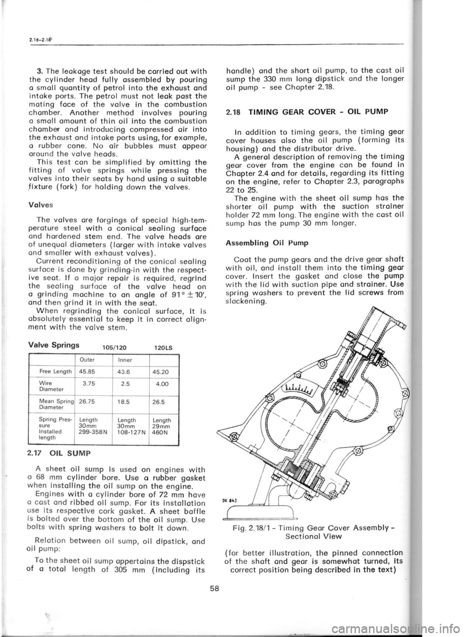
Fi1.2.1811- Timing
Geor Cover Assembly -
Sectionol View
(for better illustrotion, the pinned
connection
of the shoft ond geor
is somewhot turned, its
correct position
being described in the text)
2.17
OIL SUMP
A sheet oil sump is used on engines with
o 68 mm cylinder bore.
Use o rubber gosket
when instolling the oil sump
on the engine.
Engines with o cylinder bore of 72 mm hove
o cost ond ribbed
oil sump. For its instollotion
use its respective
cork gosket.
A sheet boffle
is bolted
over the bottom of the oil sump.
Use
bolts with spring woshers to bolt it
down.
Relotion between oil sump,
oil dipstick, ond
oil pump:
To the sheet
oil sump oppertoins the dispstick
of o totol length
of 305 mm (including
its For
egi
stroiner v brrocket r
65 mm), 1
(the leng
proximott
The go
provides
geors. lf
gosket is
thicker tl" To prer
obnormol
respectivr
limits spr
Seol F it
the
t ig hte
n in1
thot it pr
edge of tl
Assemblir 1. Thre
brocket, s
pointing r
odio.4c in the pr
bore (pin
the pinne
When c
sure thot
line with
is importr
ignition d
To prev
ing durin
o pilot
m<
Then con
using o sr
2. After
ensure tl'
0.1 mm) I
3. Fit t
into the f
under the
Betwee
driven
I driven
I Axiol
c
I betwee
I and lid
58
Page 214 of 238

Fig.
15.3/8 -
Distributor Adiusting Elements
1 -
contoct holder, 2 -
rotor orm, 3- com,
4 -
distributor brocket, 5 -
distributor brocket
clomping bolt
Alwoys turn the engine clockwise to eliminote ony ploy
in the distributor drive geor
ond to
ovoid loosening of the bolt. To relieve the
com-
pression resistonce, it
is recommended to bock
off the sporking plugs.
b) Stroboscopic method:
When using this method, the volues of the
bosic ignition timing ond
the odvonce con-
trolled by the centrifugol timing control (for
its
diogrom refer to Chopter 13.5) should be odded
upwhile multiplying bytwo
the odded upvolues
occording to the diogrom. Any effect of the
vocuum control must be
eliminoted by discorr-
necting the respective hose (connecting
the
distributor vocuum unit with the corburettor).
The meosuring procedure
is indicoted by the
diognostic equipment itself.
To Adiust ldling Speed
Use the oir-correction screw (speed
cor-
rection screw). The speed decreoses when ro-
toting the screw clockwise ond increoses when
rototing it onticlockwise.
Adiust the idling speed in occordonce with
the tochometer ond within the limits specified
in the following porogroph "To
Adiust ldle
Run". The engine must be wormed-up
before
storting the odjusting procedure (see
olso the
following porogrophs) ond its ignition must be
in perfect
condition (distributor
contoct-breoker
points, sporking plug
electrodes, ond ignition
odvonce).
N o t e : For the bosic position
of the odiusting
screw refer to Chopter 2.19 - "Mointenonce
ond
Adiusting". Fig.
15.3/9 -
Air-correction Screw -
idling speed
correction screw
To Adiust ldle
Run
Acljust the contoct-breoker point
gop,
the gop
of the sporking plug
electrodes, ond
the ig-
nition odvonce. Then check
the
volve cleoronce
(if there is no cleoronce, odiust
the
volves),
cleon the oir intoke filter
element, ond moke
sure thot the occelerotor pedol link hos
the re'
quired free trovel -
see Chopter 12.2-
Use o needle to remove the plug
covering
the fost-idling screw
ond let the engine run ot
obout 2,000 r. p.
m. to ottoin on oil temperoture
of 70oC. Insert the probe
of the thermonreter
into the hole for the oil diPstick'
Now connect the
speed indicotor (tocho-
meter) ond the onolyzer of
corbon
.monoxide
(contoined in exhoust fumes). Use
the oir'cor-
iection screw (Fig.
15.3/9) to set the
speed
-r-?n
at 800 l;; t.
p. ni. cnd the fost-idling screw
(Fiq. 15.3/10) to odiust the
content of corbon
moioxide to 2*0.50/s or the oir-fuel proportion-
by-weight mixing rotio,
comporoble with
the
specif ied corbon monoxide content, to
1+.2 +$.t.
After about one minute of
the continued idle
running recheck the odiustment ond
correct it,
if necelsory. Close the hole
with the
fost-idling
screw by driving in o
new plug with
its bottom
outword.
Note: For the bosic position of
odiusting
screws refer to Chopter 2.19 - "Mointenonce
ond Adjustment".
To Lubricote Accelerotor Mechonism
Pour severol drops of oil into
the end of the
bowden coble tubing ond lubricote both
ioints
(on top ond below)- of the corburettor pull-rod
itself with obout one drop of oil. Then
depress
224
Page 216 of 238

friction focing. lnodequote
ploy
results irr o too
short free trovel of the clutch pedol
ond on
olmost immediote clutch disengogement. Access
to the releose
cylinder con be goined
os de-
scribed in the previous porogroph
on clutch
lubricotion. Hold the rod protruding from
the
relose cylinder ond force
from it corefully the
releose lever, ogoinst which it is restingi
the
lever con be relieved by disengoging the ten-
sion (pull-off
) springs.
ln service, the forcing-off
must be ot leost
2 mm. Adiust it to 4
to 5 mm by odiusting the
length of the rod. After hoving
loosened the nut
on the rod
of the releose cylinder, rotote
the
releose finger to obtoin the correct rod
length.
Then retighten the nut, thus locking the releose
f inger in its position
on the rod.
lf the ploy
is correctly od justed,
the f ree
trovel of the
clutch pedol
pod should ronge
from 40 to 50 mm. lt should not be ollowed to
drop below '!0
to 15 mm. lf the described od-
justing procedure foils to bring the required
result, it is necessory to odjust the clutch
mech-
onism in occordonce with
informotion con
toined in Chopter 3.2.
Bleeding the Glutch Hydroulic System
The movement of the clutch pedol
is trons-
mitted hydroulicolly to the clutch releose cylin-
der. The couses ond symptoms of penetrotion
of oir into the hydroulic
system (similor
to the
broke hydroulic system) ore described in detoil
in the section deoling with brokes. The pro-
cedure of bleeding the clutch is the some os
wherr bleeding the brokes -
see Chopter 15.8.
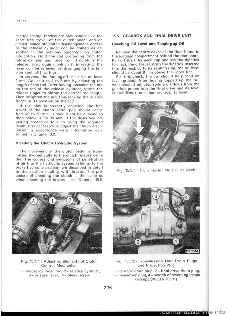
Fig. 15.411-
Adiusting Elements of
Clutch
Control Mechonism
I -
releose cylinder rod, 2 -
releose cylinder,
3 -
releose lever, 4 -
bleed screw 15.5 GEARBOX
AND FINAL DRIVE UNIT
Checking Oil
Level ond Topping'up
Oil
Renrove the centre cover ol the
f loor boord in
the luggoge comportment behind the
reor seots.
Pull off the filler neck cop ond use
the dipstick
to check the oil level. With the diPstick inserted
into the neck up to its seoling ring, the oil level
should be obout 8 mm obove the upper line'
For this check, the cor
should be ploced
on
level ground.
After hoving topped up the oil,
woit obout 2 minutes (while
oil flows from the
georbox proper
into the finol drive ond its level
is stobilized), ond then recheck
its level-
Fig. 15.5/1 -
Tronsmission Unit Filler Neck
Fig. 15.512 -
Tronsmission Unit Droin
Plugs
ond Inspection Plug
1 -
georbox droin plug,
2 -
finol drive droin plug,
3 -
inspection plug,
4 -
switch of reversing lcmps
(except SKoDA 105 S)
ffi
;rt'i,*
tiiffi
ii.! i;
br'ill
226
Page 224 of 238

16.1
-
16.2
16.1 EQUTPMENT FOR SUBTROPTCAL
REGIONS
Stondord equipment of
cors for subtropicol
regions where the temperoture
does not exceed
+40oC, or where
increosed
cooling efficiency is
required generolly:
1. Copper rodiotor (copper
lominotions) for
oll types. 2. Oil cooler for oll types,
the some
os thot
fitted in the stondord
12O LS
model.
3. Cost finned
oil sump for oll types includ-
ing occessories (longer
oil pump
suction
stroiner ond longer oil dipstick), like thot fit-
ted in
stondord 120 L ond 120 LS models.
4. Oil temperoture signolling
telethermometer
(125+3'C) in cor type S 120 t-S.
The primory
element is mounted in o speciol connection fit-
ted to the oil cooler outlet. The worning lomp
on the instrument ponel
is red
ond without
o symbol (the
instrument ponel
hos o different
wiring for the connection of the worning lomp
to the terminol boord).
The coble of the primory
element is con-
nected to the terminol "10"
of the terminol
boord "111"
(morking occording to wiring dio-
grom in Fig. 13.1/1).
The
coble is led out ot
the engine together with
cobles to the engine
temperoture gouge
ond the oil pressure
switch.
16.2 EQUTPMENT FOR TROP|CAL
REGTONS
Stondord equipment of cors for tropicol re-
gions where the temperoture does not exceed f
50 oC,
or where on
extro high cooling
ef-
f iciency is required generolly:
1. Copper rodiotor (copper
lominotions) for
oll cor types.
2. Oil cooler for
oll types like thot fitted
in
stondord S 120 LS mod6l. The bolt
connecting
the rodiotor hose of the outlet from the engine
timing geor cover to the rodiotor hos, however,
no by-poss holes.
3. Cost finned
oil sump
for oll cor types -
refer to Chopter 16.1, porogroph
3.
4. Oil temperoture signolling telethermometer
(125+3oC) for types 120 L
ond 120 LS.
For
loyout see Chopter 16.1, porogroph
4.
5. Thermostot with o nominol opening tem-
peroture of +75oC for oll
types.
6- Increosed volume of coolont (storoge)
tonk -
4 litres for oll types.
7. Fr-rel pump
with o longer priming
lever.
It is instolled on the engine on two insuloting
pcrd s
Mointenonce of oir clecner:
The stondord oir cleoner filter element (the
some for oll cor types) must be
chonged in
dust-loden environments ofter every 2,000
kilo-
metres. On dusty roods in deserts, this element
must be inspected doily ond reploced doily, it
necessory.
Keep the coolont level
ot obout the middle
of the tonk or only slightly obove the middle.
The totol
volume is 13 5 litres opproximotely
234