1980 SKODA 120 LSE oil
[x] Cancel search: oilPage 40 of 238

For the
instol lotion of the engine on the test
bench, we indicote the dimensions
of the en'
gine flonge ond flywheel. During broking, the
engine qnd
the engine oil must
be properly
cooled to preclude
exceeding the oPtimum
service conditions, i. e. woter temperoture
ofobout
80 to 90oC, ond oil temperoture of 12O"C
moximum -
see Chopter 2.5,
porogroph 51.
Engine Lubricotion
The inner lubricoting oil distribution system
is shown in Fig.2.5/5.
6 DK .r5+9 2.6
cYL
The cyl
mochined
the cronl
ports, forr
ore mode
B locks fo
72 mm di
I i ners.
Oilwoys, I
o) Befo
o new cyl
ossembled
blow thror"
b) Coot
pound or p
the oilwoy
c) Likev
into the e
pound or p,
of the
cyli
one (of
lo
limits indi
Ports) to er
d) Tighte
ot cylinder
under it.
e) Foster
the cop of
Fosten the
with o bolt
Fig.2.611 ond
1 -
choin gre
plug, 3 -
iniel
relief volve,
with cop, 6 -
inlet from o
ptug, I
9
8
7
5t
Fig.2.515 -
Engine Lubricotion Diognom
Skodo 120 LS
engine hos,
in oddition, on oil cooler incorporoted between the punrp
delivery
broncir on the timing geor
cover ond the moin oilwoy (see
Fi9.11.9)
srlctionstroiner,2-pump,3-pressurereliefvolve,4-moinoilwoy,5-oil filter,6-by-poss
hole, 7- oil pressure
switch, 8-pulsotingchomber, 9- rocker orms, 10-connecting rod
splosh hole, 11 -
choin splosh screw
4
2
4 t-
oil I
?
?
I
;
t
Page 42 of 238
2.6-2.7
seot in the cylinder block using o copper or
oluminium rod.
Reconditioning Recesses for
Cylinder Liner
Flonges
Before ossembling o used
cylinder block,
inspect ond cleorr thoroughly the moting
sur-
foces of the recesses for
cylinder liner f
longes.
lf chemicol ogents (petrol,
etc.) foil
to hove
the required
effect, or if the surfoces hove
been domoged
mechonicolly, use the MP 1-106
dresser, or the MP 1-157
iig with
universol guicc
rings.
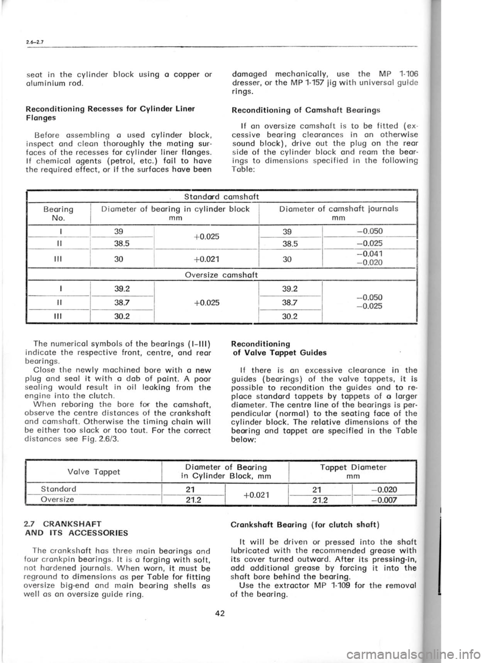
Reconditioning of Comshqft Beorings
lf on oversize
comshoft is to be f itted (ex-
cessive beoring cleoronces in on otherwise
sound block), drive out the plug
on the reor
side of the cvlinder block ond reom
the beor-
ings to dimensions specif ied in the following
Toble:
-0.025To
Grind
For grir
shoft by t
between 1
'Ihe
reor
ond there
for detoils
beoring.
For grir
prepored
clomped t,
pins must
Externol Col
Nomir iourn
Stondord
1st regrin
2nd regrin
3rd regrin
Stondond comshoft
Diometer of beoring in cylinder block
mm
+0.02s
38.5
+0.021
Oversize comshoft lsg
l-
38s-
l-;- -0.041
-0.020
The numerical symbols of the beorings (
l-lll)
indicote the respective
front, centre, ond reor
beari ngs.
Close the newly
mochined bore with o new
plug ond seol
it with o dob of point.
A poor
seoling would result in oil leoking
from the
engine into the clutch.
When reboring the bore for
the comshoft,
observe the centre distonces of the cronkshoft
ond comshoft. Otherwise the timing choin will
be either too slock or too tout. For the correct
distonces see
Fio. 2.6/3. Reconditioning
of Volve Toppet Guides
lf there is on excessive cleoronce in the
guides (beorings) of the volve toppets,
it is
possible to recondition the guides
ond to re-
ploce stondord toppets by toppets
of o lorger
diometer. The centre line of the beorings
is per-
pendiculor (normol) to the seoting foce
of the
cylinder block. The relotive dimensions
of the
beoning ond toppet ore
specified in
the Toble
below: o
L_r
_-L1il I toi .ll
-t
QZt0.l -T-
zi
A'ry
@)
2.7 CRANKSHAFT
AND ITS ACCESSORIES
The cronkshoft hos three rnoin beorings ond
four cronkpin beorings. lt is o forging with sof t,
not hordened iournols. When
worn, it
must be
reground to dimensions os per
Toble for fitting
oversize big-end ond moin beoring shells
os
well os cn oversize guide
ring. Cronkshoft Beoring
(for
clutch shoft)
It will be driven or pressed
into the shoft
lubricoted with the recommended greose
with
its cover turned outword.
After its pressing-in,
odd odditionol greose
by forcing it into the
shoft bore behind the beoring.
Use the extroctor MP 1-109 for
the removol
of the
beoring. Diometer of comshoft
iournols
mm
_ =l__i tl
Volve Toppet Diometer
of Beoring
in Cylinder Block, mmToppet
Diometer
mm
Stondord
on;rsizt- 21
+0.021 21
-0.020
21.2 21.2-0.007
42 4th
Page 44 of 238
2.7.-2.8
Guide Rings Regrinding of the foce of the front
cronkshoft
web results in
on increosed (oxiol) ploy
of the
shoft. Reploce therefore the originol guide
ring with
on oversize one. Oversize guide
rings ore fitted exclusively
to
the regrround loterol
foce of the cronkshoft web.
Stondord size rings
should be olwoys fitted
to
the thrust ring side (next
to the timing geor).
Thrust Ring
lf the thrust ring under the cronkshoft timing
geor (sprocket)
obutting ogoinst the guide
ring is worn to on
extent
which mokes domoge of
the guide
ring likely, reploce it
with o new one
or regrind it.
The moximum permissible
regrinding is, how-
ever, to o thickness of only 3.75 mm.
Cronkshoft Moin Beoring Shells
Fit the cronkshoft moin beorings (shells)
occording to the respective nominol diometer
of the cronkshoft
iounnols. The shells
ore not
provided with o diometer symbol so thot they
hove to be checked for
the respective woll
thickness with o micrometer.
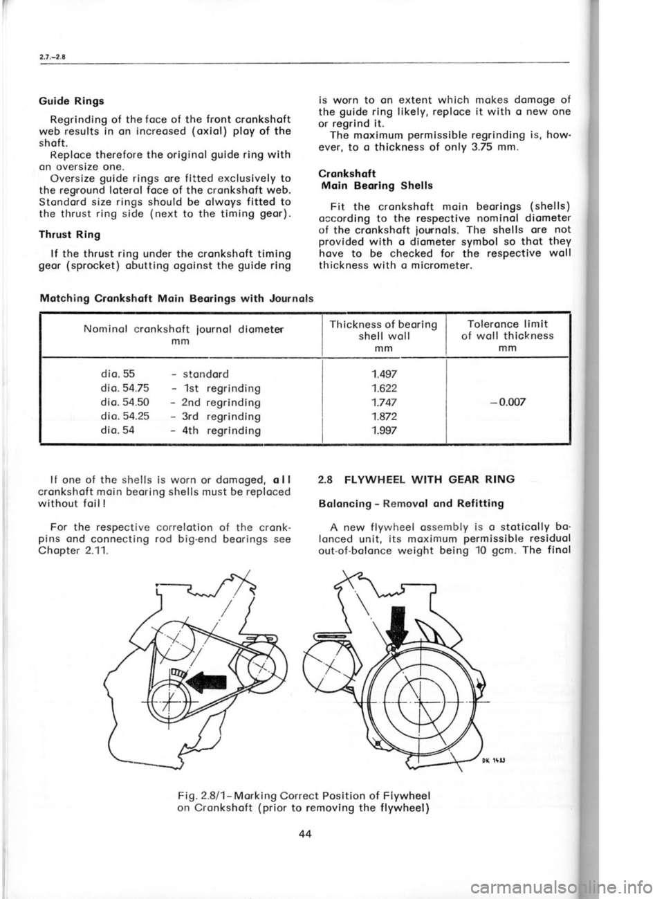
2.8 FLYWHEEL WITH GEAR RING
Boloncing -
Removol ond Refitting
A new flywheel ossembly is o
stoticolly bo-
lonced unit, its moximum permissible residuol
out-of-bolonce weight being '10
gcm. The finol
lf one of the
shells
is worn or domoged, o ll
cronkshoft moin beoring shells must be reploced without foil !
For the respective correlotion of the cronk-
pins ond connecting rod
big-end beorings see
Chopter 2.11. dynomi<
ism shr
sembfed
Thus
sitioq of
shoft be
from o
1
When
rnork on
zero line
ond prol
mork op
cylinder
the rem<
gcm sin
mosses (
concentr
cronksho
holes rot
wheel ir
interf erel
For thi
on the r
sition, i.
cronksho
fore the
When
one or wl
follows:
1. Fit .
residuol o
olly offec
2. The
bolonce r
hos o hig
correctior
once. lt
occording
porogroph
Chopter 1
bending t
To Reploc
Reploce
worn or d,
ring, toke
the interfr
sion). The
prime impr
ossembly
storter mo
The gec
removed b
port pod
cr
MP 1-153. I
ing the ge
it off. The
monufoctut
When ur
front foce
ond drill
o
Fig.2.8l1- Morking
Correct Position of
on Cronkshoft (prior
to removing theFlywheel
f lywheel)
Motching
Cronkshoft Main Beorings with Journols
Nominol cronkshoft mmiournol
diometer Thickness
of beoring
shell woll
mm Toleronce limit
of woll thickness
mm
dio. 55 dio.54.75
dio. 54.50 dio.54.25
dio. 54 stondord
1st regrinding
2nd regrinding
3rd regrinding
4th regrinding 1.497
1.622
1.747
1.872
1.997
-
0.007
44
Page 48 of 238
![SKODA 120 LSE 1980 Workshop Manual Nominol
diometer
mm Gudgeon
pin
diometer mIn Pin
bore
in piston
nl
n] Connecting
rod
smoll-end bore
(br-rsh diometer)
mm
20
20.0s 20
-
0.003
20.0s --
0.003 -
0.004
zu - o.o1o
,o 05, 3 3 SKODA 120 LSE 1980 Workshop Manual Nominol
diometer
mm Gudgeon
pin
diometer mIn Pin
bore
in piston
nl
n] Connecting
rod
smoll-end bore
(br-rsh diometer)
mm
20
20.0s 20
-
0.003
20.0s --
0.003 -
0.004
zu - o.o1o
,o 05, 3 3](/manual-img/3/57425/w960_57425-47.png)
Nominol
diometer
mm Gudgeon
pin
diometer mIn Pin
bore
in piston
nl
n] Connecting
rod
smoll-end bore
(br-rsh diometer)
mm
20
20.0s 20
-
0.003
20.0s --
0.003 -
0.004
zu - o.o1o
,o 05, 3 3?3 2a
13 33?
,o os
13
33?
Toble
ofMotching GudgeonPins
to Pistons ond
Smoll'end Bushes The
cler
should be
cleoronce
the rings
2.11 COn
The con
o brorrze
b
beoring sh
in the big
Before r
for compli<
weight, ol
ond motch
shoft.
For its
<
ter 2.12.
To Check
Connecti
weight gror
foctory, ligl
yellow poi
Should the
during stor
been fitted
determ ined
remove o c
smoll ond t
the smoll
r
in the
engi
(+2 gr.).
When re
odjust its w
connecting
DK 63:
Fig
'l - boloncing
2 -
numericol
GUDGEON
PIN
Tlre gr-rdgeon pin
is cr slight interference f it in
the piston-
lts cleoronce in the
connecting rod
smoll-end bush is:;pecified in
the Chopter
"Connecting Rocl ".
The steel gudgeon pin
is lrollow ond hos
c rronrinol cl iometer of 20 ntnr,
replocement pitts
l.rovirrg; o nominol dionreter of
20.05 mnr. When
f itting on oversize gudgeon
pin with 20.05 mm
nomincl diometer, the bore
toking the pin must
be reomed to dimerrsions
specif ied irr the re-
spective l-oble.
PISTON RINGS
To ensure their correct function, they must
be f itted in the correct position, they
must hove
no or onlv c minimum cleoronce clong
their
r:ircumference, o smqll
cleoronce in
the gops'
ond tlrey mLrst rrove freely in the piston
grooves.
DK 1436
Fig.2.1Ol3 .-
Seqerence ond
[Jlethod ot Fitlingl
Piston Rings
( Mork Positioning).
Fronr top to bottom: chromium-ploted compres-
sior.r rinq, bevelied compression ring,
spring
locrded exponding oil control ring
Fit the {irst ring in cny orbitrory position
(its cylindricol chromium-ploted peripherol
port
is chomfered on either side,
focilitoting identi-
f icotion), the second, bevelled ring with
the
lettering 'TOP"
or onother mork
on top, ond
llre oil lontrol ring with its
outer shorp
edge g>ointirig
dowtrword. lf
tl-rere is
ony doubt os
to
the coriect selection of
the rings, check them
for proper seoling in
the cyli.nder.before os-
rurbty. ltrsert tlre ring into
the cylinder ond
level it by pLrshing
home the piston heod' In
the cose of
o used cylinder, insert
the ring
obout 20 ntin
below the
top edge of the cylinder
lirrer, i. e.
o plcce rvhere the
cylinder. liner
is
olreodv worn, while checking for
the right
clecronce in the piston
groove ond for the
correct gcrp in the
cYlinder bore.
For ri"ngs
thot hove not
been run-in,
the
fol'
lowirrg circumferentiol gop or
contoct cleoronce
with rlgord to
the cvlinder liner
is permissible:
none foi the chromir-rm-ploted compression
ring,
two in c totol ronge
of on ongle of
35 degr' for
the bevellecl compression ring
ond the oil
control ring. Lcrger
contcct cleoronces olong
the circumTerence denote
either on
incorrect
selection of
the ring, for exomple the
ring
does
not correspond to
the cylinder bore, or
on
excessive weor
of the cylinder liner.
Check the ring gop cleorcnce using
feeler
goLrges- For new
compressiol
lngs, this
gop
.leo"ronc" should
be
0.25 to 0.40 ntm, for
new
oil corrtrol rings
0.20 to 0.35 nrnr. The
nloxinrtlttt
oernrissible cleoronce
of
worn rings is 1mm'
48
105 r20
'.;iA
'!.t l
\Lt { .,
x),:=
s!-9
f:ig.2.1A14 -
Checkinq Pi.;ton Ring
Gop
Page 50 of 238
{
Smoll End ond
Big End Alignment
A misolignment of the centre line
of the
smoll-end bush ond big-end beoring
or the bore
for the big-end
beoring shells must never ex-
ceed 0.03
mm per 'lO0
mm of the connecting
rod length. For checking
ond olignment use
the
MP 1-102 or 1-159 f ixture.
Insert the odiusting pin
into the fixture ond
set both its diol indicotors to
zero. Clomp the
connecting rod without shells
into the fixture,
threod the pilot
pin
in it, ond swing
down the
connecting rod. The recdings
of the diol indi-
cotors will
show ony misolignment of the
smoll
ond big end. The moximum misolignment must
not exceed 0.03
mm os olreody mentioned.
Check for misolignment in two plones by tilting
the diol indicotors.
Two pilot
pins ore supplied, one with o
di-
ometer of 20 rnnr. the
other with o diometer of
20.05 mm, to motch the gudgeon
Pins.
To Motch Connecting Rod
with Gudgeon Pin
ond Cronkshoft
With regord to the reciprocoting movement
of the piston,
the gudgeon pin must hove
the
smollest possible
cleoronce in the
connecting
rod small end (ony lorger cleorcnce results
in
pin knocking). Therefore
select from
severol
gudgeon pins
one which will
be o close running
fit in the smoll-end
bush. lf no suclr pin is
ovoiloble, reom
tlre bush but never exceed the
moximum toleronce limits.
An oversize buslr lros to be
reomed to o nom-
inol diometer of 20.05 mm. For
the respective
dimensions refer to
the Toble supplied with
gudgeon pins. The big"end
beorings
i:;hells)
inouta be
selected occording to the nominol
diometer of the cronkpin. The
shells lrove no
diometer ntorking
oncl hove to be identif !ed
by meosuring their woll thickness with o mi'
crometer.
Motching Big-end Beoring
shells
with Cronkpins
MotchingCronkpin o"|,,n"iifl",,l ro,u,on
nominol diometer
1 thick"ness
mm
mm mm
45 (stondord)
44.75 (1st
regrinding)
44.50 (2nd
regrinding)
44.25 (3rd regrinding)
44 {:lttr regrinding) 1.490
1.615
1.740
1.865
1 990 0.007
Numericol lderrtif icotion of
Connecting Rods
For better identificotion, {igures con
be
stomped on the bosses of
the connecting rod
big end ( see Fig 2 11
1) . The f igures corre-spond with
the
number of the respective
gVtin-
derwithwhich theconnecting rod
is ossembled.
When replocing o connecting rod,
provide the
new connecting rod
with its very some identi-
ficction numbel. Stomp
the figures os much
toword the for end of the boss os possible to
ovoid fouling the loterol guide foce.
2.12 CYLINDERS, CONNECTING RODS
AND PISTONS
o) Only o cylinder (liner)
ond piston of
equot
'
diometer ond the some toleronce closs con
be ossembled qs
s unit.
b) Theengine cs qn
ossembly unit con befitted
cnly with cylinder liners ond pistons
of the
some diometer, the pistons being
of the
some weight grnLtp.
The inclividuol cylinder'cnd-piston qssemblies
con be, however, of dif
ferent toleronce
closses. On the othe'r hond, connecting rods
of only the sqme weight group
con be used-
These ore the cc;tditions for
the correct op-
erotion of pistons in the
cylinders ond for the
correct boloncing of the cronk mechonism.
For detoils concerning dimensions (diometers),
toleronce closses (cylinder liners, pistons) ond
weight groups
(connecting rods ond pistons)'
refei to fhe chcpters deoling with
the
individuol
pc|rts"
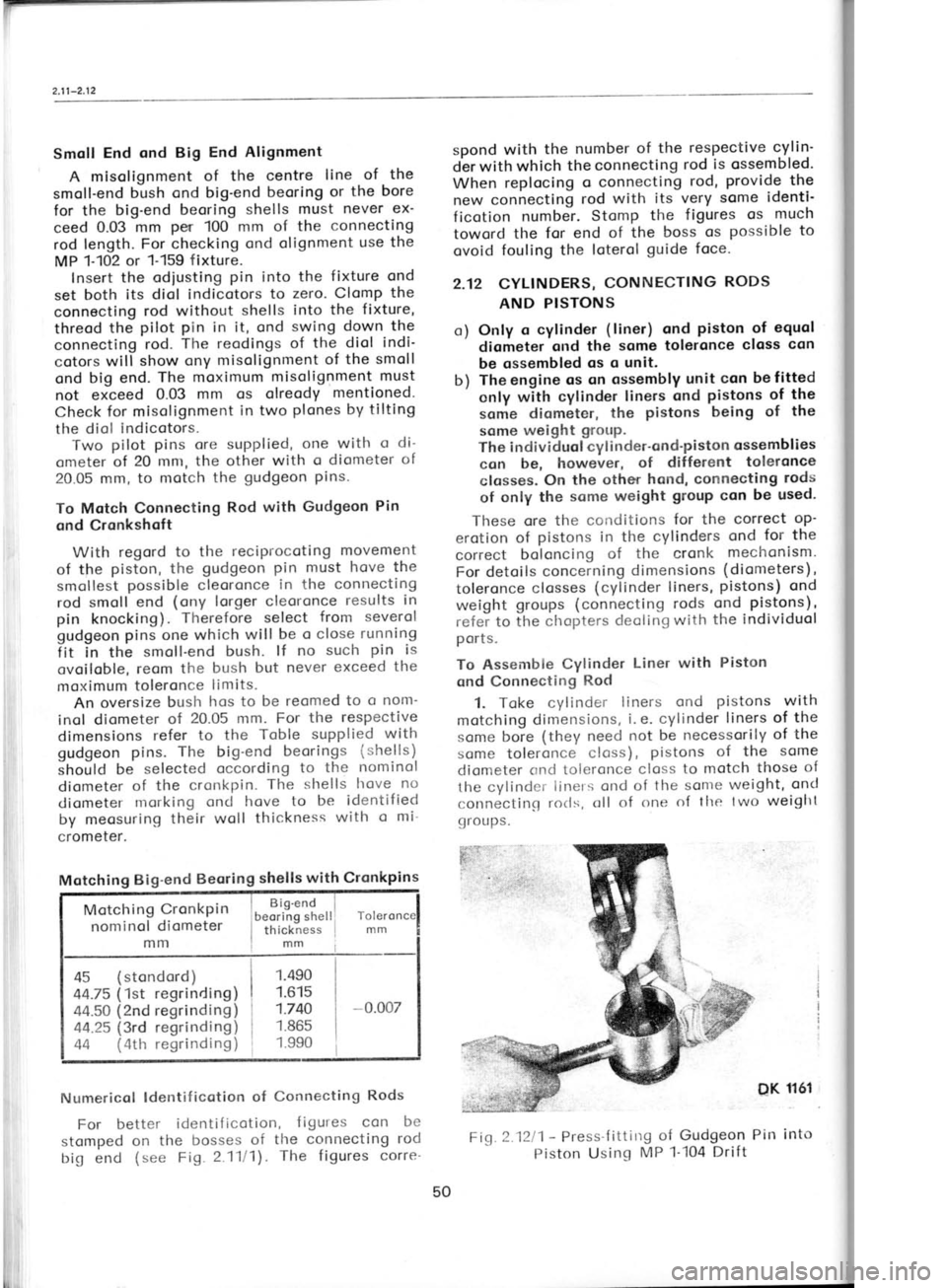
To Assembie Cylinder Liner
with Piston
qnd Connectirrg Rod
1. Toke cylinder liners ond pistons with
motching dinrensions, i. e.
cylinder liners of the
some boie (they need
not be necessorily of the
scrme toleronce closs), pistons
of the some
cliometer <,nrl tcieronce closs
to motch those of
the cvlinclr:i iitrers
ond of the sonre weight, oncl
connectitrct rorls,
tlle twtl weiglrt
cl roLr PS.
lti''
DK 1161 2.
1
OCCorl Selec'
cyl i nd
tolpro
the (
motch Son
pin or
gudge
in wh
suitob
bush.
Mor
respor
with v
meric<
Rod'.
3.L
the gr-
80"c i Sme
home
some
threod
Pin, o
circlip
on thr
pressi I
Fit
hole ir
the orr
4.F
or exp
detoils
the ri
groove
5- Pr
the crc
ond co
2.13 I
In or
ter ist ic
coms o
comsh<
c leoror
the cor
Volve '
with
lntoker
open be
close o
Fi,c 2.1211 -
Press'f ittirrg
of Gudgeon Pin into
Piston Usinq MP 1-i04
Drift
50
Page 51 of 238
t9
:r,uorODtp 6urnno;
-lol eql qllrvt
acuoploccD ur 6ulpaacold epLllvr
palsnlpo eq uoJ .rapug;lc retllouD
lo sa^lD^
qloq
lo eouoJoelc
aql'sa1oura1;o .rapul;Ac euo,o
srrlJo JalcoJ aAlD^ eql
]o lueure^ouJ eql uaqnn
'pasolc eAlD^
aql qllr*
e3uorDalc eq1
lsnlpy 'ulJD
re)oor eql
puD e^lD^ eql
lo spuDl eql
uearv\laq
Peuosu!
e6no6 Jeleal
D esn acuoJDelc e^loA aql 6u11caqc
ro3'Arosseceu sD sJe)cor e^lo^ oql
lo u!d
llDq eql alDlor 'e3uDrDelc
e^lo^ aql
lsnlpo o1
Luru 0z'0 S1 OZL DPOIS
ruru 0z'0 urLu
EL'0 -l
ozl puo
901 DpoIS
e^lD^ lsnoqx:l e^lo^ elolul
:elqol 6uqrnr'o11o1 eql ol 6ulp.rocco
au16ua ploc
D uo ecuDroelc e^lD^
aq1
1snlpy
ecuDloalc onlDn ec!AJes
ulDrlC puD
sroee 6urtu11 -LltL'Z'61)
or{r u o
r rD u e
q
},";(J -il",f
L::t i"1"'
i J,i? Tfr :;
.roe6 goqsluD.rc
eql uo
lrDlu aql
rano a;]ugd
aq1) .roe6
lloqsuoc aql
uo
lrDrx eql
puo
UDqs
-),luorc aql uo
1:ou (qcund)
6urrurl eqt uaeMloq
ero (s1u11)
segtuld urDqc
zL lDr{} os
(slelcotds)
sroa6 6u1ru!l eql uo pelllt
uroqc o
1o suoeu
lq
UoqsluDrc aqr
qllr,t paldnoc
sr
llDqsruDc eql s't
ozt DPoIs
1ozt '90t
Dpols se^lDn elDlul
:r.ur.u gt'0
ol
les e3uoroelc e^lo^ eql
qUM
6u1tu;1 en1o1
'.roa6 an;on aLtl Jo uorlolado
loellog aql
Jol ecuDuodut ar-uud
Jo sJo]ool
aro ocuoJDelc
eAIDA lceJJoc puo
lloqsluolc eLl] ol
lJoqsuoc
eql lo 6urqdnoc eql 'orlDJ
Jelool a^lD^ puo
surDc
eql lo u:eltod
puD
uotlrsod so qcns 'sorlsrJel
-JDJDqc u6rsap enrlcadsar eql ol uollrppo ul
uv39 fnlv^ tL'z
'(,,rpoU 6u11ceuuo3,, .re1doq3 aes) ranoc puo
pua 61q po.r
6uglcauuoc aql olur
llDr.ls>luoro eql
ql!r',t peLlclouJ se^loq
;1eqs 6ur.roaq
sseJd 's
^
'seAooJD
uols1d aql u!
luaua^our eaJl ro] s6u1r eql
lceqC ',,s6u1g
uols!d,, raldoq3 aLl] eas sllolep
.ro1 's.ra6u1l
sql qllm
s6ulr aq1 6urpuodxa ro
sre11d ;olcads 6u1sn s6ug.r uolsrd
aql
llj 't
'Slt'Z'6lJ eas -
poeq uolsrd sql uo /v\or,rD eql
lo spls algsoddo
eql seco' pua
6rq slr ut aloq
qsolds aqt
lDrll os
por
6ullcauuoc eql
l!l
'u1d uoe6pn6 aql auoq 6ursserd
iol lilJp logceds aql
asn 'dr1c-r1c
reqlo eql uo
d11s lgloug3 'a1oq
uols1d ellsoddo aq] ul
drlcrrc
aql sD JD] sD u1d uoe6pn6
"qr qsnd puo 'urd
uoe6pn6 aql uo qsnq pua-llDr.us pel!o
aLll poerql
'a6pe aloq uolsgd eql puoAeq
uu g'L
ol
L suJos
sepn:1o.rd 1 lorll os uolsgd
pelDeq
eq] otu! euoq
1l dDl
puo
llo qltru
utd uoa6pn6 eLl] roeus
'JalDM loq Jo acDurn]
6u11oaq p
u!
Co08
lnoqo o1
uolsrd aql
loeLl puo
u;d uoa6pn6 eql
uo d1;cr1c aql ecold 'slegld
;orceds 6urs6 'g
'.pou
6u11ceuuo3,, .ra1doq3 eql ol JeleJ epoc lDc!Jer.ll
-nu aql roJ 'pelquesD
eq 1ilrt Aaqt
qsrqM qllM
srapul;lc lo si€qunu ropro aql o1 Dugpuodsar
-roc sJequlnu qllM
spol 6urlcauuoc eql >lrou\
'qsnq
eql uroer 'puoq
lo lou s!
urd
uoa6pn6 a;qoilns
'reqlouo 11 '11;
6uluunr D
aq plnoqs
l! qcrqrlt
ut
'qsnq eql olur pauasu!
eq
louuoc u1d uoe6pn6
eql ]oql os
qsDlc qsnq pus-llous
aql puo
u1d
uoa6pn6 oql
io sl!uI!l eouD.rolol saur!leuoS
-uraq] ro; surd uoa6pn6 6urqclour
lcelos puD
(,,pou
6u11cauuo3,, :a1doq3 eql
ees) spo.r 6ullcauuoc
eql u6!lo :ssolc acuoJalol
anllcadse.r aql ql!M
6u1daa1 ur
reu!l rapu;;lc
qcDo ro' po.r
6ullcauuoc o puo
uo1sld D
lceles
'g'7 .reldoqC eLll
1o g; qdoroo.rod
o1 oulp.rocco
lcolq ropu;;Ic eq1
olul sreu!l aqt
llolsul 'Z
,0t.Et
'OtoiL ,0t"9t
,0eoDL
ccl8
rello
esolc
361 arolaq
uedo
flt"l
,0eo9? ,0Cr0L
,0Lo0?ccf
JeuD ssolc
369 a:o;aq
uado
{0/Zt lSO! se eures
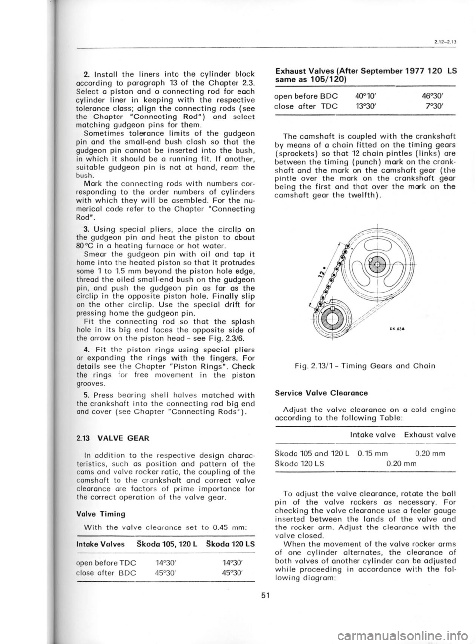
ST OZ I LL61 requaldes reUV)
sa^len
lsneqxl
s c\lut
utr
r9r! x0
!
1r;6gem <
puo '1q6
jo esoql
otxDS at
eq1 1o i1
eLll lo sJ
9]!M su
u(
lDnp!^!pr
' (suo1s;d
puo (suc
' (sleleur
'uJsluDr.ls
eqt rol I
-do lce.r.r
'pasn aq
spor 6ug1
ocuDJaloi
se!lqrues
aq1 ;o t
eql lo sr
pell!l eq
uDc ssDli
lonbe ;o
SCr
ol alq!ssl qcntu sD
-!luop! or.
eql eP!^(
'polquros{
-u11lc en;
Et z-zl'z
Page 52 of 238

Alternoting
cylinder No. 1
cylinder No.3
cylinder No.4
cylinder No. 2 Adjust cleoronce
on
cylinder No.4
cylinder No.2
cylinder No. 1
cylinder No.3
Fi1.2.1312
-
Volve Cleoronce Adjustment link from the choin
front side ond fit the clip
from the reor with its open end pointing in
the
direction opposite to the choin movement.
Before storting work on the volve geor,
re-
move the oil sump (engine
bottom cover to
which the timing geor
cover is bolted, the suc-
tion stroiner being ottoched to the cronkshoft
centre beoring cover) ond lock
the cronkshoft
in position
in the oxiol direction by depressing
the clutch pedol,
if removol of the entire engine
is not intended for onother purpose.
For speciol
points of the removol refer to
Chopter 2.4.
2.14 WATER PUMP
Disossembly 1. Unlock the wosher of the belt pulley
nut,
remove the nut ond pull
off the belt pulley
using
the MP 1-120 puller (o
fixturre for
Skodo MB 1000
cors) or o universol puller,
for the bolts of which
it is necessory to
cut threods M 8 in the belt
pulley holes.
By pulling
off the belt pulley,
occess will be
goined to the nuts fostening the pump
to the
engine. The some procedure
holds good
when
dismontling the pump
ofter it hos been removed
from the engine.
2. Withdrow the keyfrom
the shoft ond, using
the drift MP 1-121, drive
or press
out the shoft.
Then lift owoy the
housing plote
from the
seoting foce of the pump.
3. Remove the circlip locking the outer boll
beoring in position.
Proceeding from the reor
side of the pump
housing, drive out the boll
beorings with their spocer tube, ond remove
the
rubber seoling rring
from the housing.
Reossembly 1. Smeor the rubber seoling ring with greose
ond insert it into the pump
housing.
Use the
MP 1-123 drift to drive home the inner boll
beoring (without
sheet guord) pocked
with
greose. When opplying the drift,
fit its guide
ring into the bore for the
oute,r boll beoring.
2. Fit the gosket
on the pump
seoting foce
ond ploce
the pump plote
with its cemented-on
gosket (focing outwords from the pump)
over it.
Fosten the plote
to the pump provisionolly
with
one bolt to prevent
the gosket
from being dom-
oged during the following ossembly
iobs.
Insert the rubber seol,
wosher, ond conicol
spring into the speciol (bokelite)
seoling ring
of the pocking glond.
Instoll the spring
with
its nose
into the hole in
the bokelite pocking.
Slip the ossembled pocking glond
on the shoft
with the spring toword the shoft geor,
ond drive
the shoft home into the pump
beoring, while
supporting the beoring with the MP 1-123 drift. Fig.2
4. Fit t
shoft ond
stolling th
in positior
it with gre
sheet guor
5. Top
t
lieve the r
@@@@
DK 1240
Fig.2.1313 -
Volve Arrongement in Cylinderr Heod
Block disks -
exhoust volves
White disks -
intoke volves
Timing Choin ond Timing
Geors
Modified chain and gears
fitted since October
1979 recognised by
squared gearteeth
and chain
with split rollers.
The timing choin hos no slock odiuster (ten-
sioner). A slock choin does not substontiolly
offect the volve geor
occurocy but its operotion
is noisy. Therefore
its correct length should
be
ensured either
o) by selecting o suitoble choin from o number
of choins ovoiloble -
try it on the timing
geors, o1r
b) by replocing the stondord comshoft geor
with on oversize geor
(with greoter
toler-
onces). The comshoft geors
ore groded
in
keeping with their progressive
size (tol-
eronces) into closses A, B ond C. With the
exception of
closs A, the closs morking
letters ore stomped next
to the punch
mork.
For trying, the choin con be disconnected
to ovoid removing ond refitting of the timing
geors. To recouple the choin, insert the coupling Fig.2.1t
52
Page 54 of 238
6.
Complete the pump
ossembly by fitting
the
Stouffer lubricotor filled with
the recommended
greose.
2.15 ROCKER SHAFT AND ROCKERS
Assembly (on
Skodo 105 engine)
1. Instoll the lock ring, ploin
wosher, ond
spring wosher on the ro6ker shoft
with both
ends plugged.
Smeor the shoft with oil, fit the
rocker (with
its orm with the thrust foce de-
flected toword the next ossembled ports),
the
shim, the rocker support, ond the other
orm
def lected toword the support, i. e. the complete
rocker unit of cylinder
No. 1.
2. Then slip the spring,
the rocker, the sup-
port, the shim,
ond the next rocker, i.e.
the
complete rocker unit of cylinder
No.2, on the
shoft.
3. Threod on the spring ond, using the mirror
orrongement of the ossembled
rocker units,
instoll the rocker
units of the remoining
two
cylinders. Use o lock ring supplemented
with
o ploin
ond o spring wosher
to lock the os-
sembled ports
in position.
The rocker support of the cylinder No.4 must
be provided
with on oil hole
to provide
for the
supply of oil to the rocker shoft.
4. Compress
the springs
by holding down the
rocker orms ond lubricote
oll loterol contoct
surfoces with oil.
Assembly (on Skodo 120 L
ond 120 LS engines)
The rocker shoft is provided
with two od-
ditionol rocker supports fitted from
the outside
of the rocker units (the
shoft is longer), re-
plocing woshers obutting
on the lock rings.
For
the rest, the ossembly is identiccl
with the pro-
cedure described in porogrophs
1 to 4 obove.
NJote: Rocker orms
on the Skodo 120 LS en-
gine ore shorter (18.5
mm) thon those on the
Skodo -120
L ond Skodo 105 engines,
in order
to obtoin o higher rotio.
Disossembly
Remove the lock ring from the shoft
end ond
strike off the
entire volve nocker geor
from
the
shoft.
2.16 CYLINDER HEAD, VALVES
AND
SPRINGS
The cylinder heod is o costing of speciol grey
cost iron. The volve seots ond guides
ore cost
ond mochined directlv in tlre heod. The volves ore of different
diometers, the intoke volves
being lorger. Outer (exhoust)
ports
ore single,
oll remoinlng ore doubled, i.e. bifurcoted
ond
bronching to two volves in odioining
cylinders.
The centre exhoust port
bronches to the cyl.
inders No.2 ond 3, the neighbouring
intoke port
to the cylinders No. 1 ond 2, ond No. 3 ond 4.
The cylinder heod con be hondled
in the cor os
o unit. Of the individuol
iobs, only
the reploce-
ment of volve springs,
cotters, ond cylinder
heod bolts con be corried out with the engine
in. position in the cor. For oll the remoining
iobs, the
cylinder heod hos to be removed
from
the cor.
To remove
the volve springs,
screw out
the
sporking plugs ond, using o tommy
bor with
o curved end (steel
bor of obout 5 mm dio-
meter), broce
the volve to prevent
it from
sliding down into the combustion
chomber.
To Remove
Cylinder Heod from Engine
1. Let
the engine cool down before removing
the cylinder heod to preclude
worping of its
beoring surfoce.
2. Droin
the coolont into o cleon vessel (see
Chopter 15.13), detoch oll ports
connecting the
cylinder heod to the vehicle,
ond remove
oll
ports which ore likely
to obstruct the removol.
3. Remove the oir cleoner,
lift owoy
the
cylinder heod cover, ond remove
the nuts ond
bolts holding down
the cylinder heod (on
en-
gines of Skodo 120 L
ond 120 LS cors, two
bolts olso hold down
the end rocker
shoft sup-
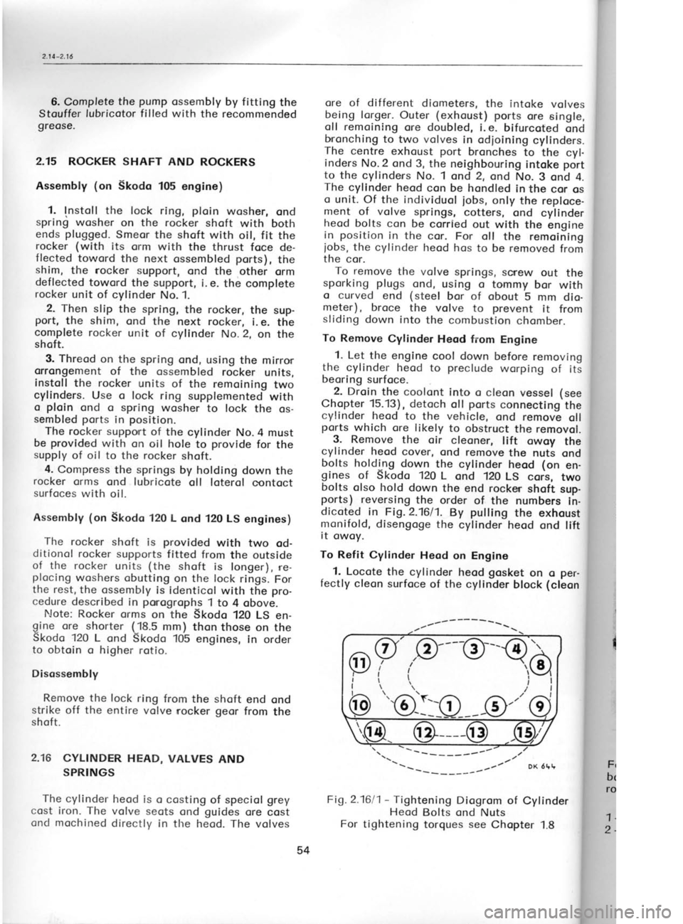
ports) reversing the order of the numbers
in-
dicoted in Fig. 2.1611.
By pulling
the exhoust
monifold, disengoge the
cylinder heod ond lift
it owoy.
To Refit Cylinder
Heod on Engine
. 1.
Locote the cylinder heod gosket
on o per-
fectly cleon surfoce of the cylinder
block (cleon
Fi1.2.1611- Tightening Diogrom of Cylinder
Heod Bolts ond Nuts
For tightening torques see Chopter
1.8 the
cylinc
the oilwo,
structed c
Releose
once odjur
heod. lf nr
the rocker
2. Swin<
down the
porogroph
opply the
liminory o
the sequ€
(Fig. 2.16/
shoft suppr
3. Adjus
ter 2.13,
re
cleoner, rer
tighten oll
Cylinder Hr
Disossem
heod on o r
o support i
it does
not
o iob from
t
An exomple
1. Remove
the cosing
control, end
geor ofter
supports.
Fig.2Je
For holding
c
bolt M 8 scrt
rocker-shoft st
1 -
MP 1-113
v,
2 -
MP 1-114
v
Itl
I
I
/\.
-
( 3 r--{ 4)
\-/
\II
l
/
,/
t___v'
?,3
"'@-:lO
54