1980 SKODA 120 LSE oil
[x] Cancel search: oilPage 99 of 238
5.5-5.7
the toe-in of the reor
wheels using olso the
MP 8-152 gouge or onother speciol gouge
ovoil-
oble in your
workshop. To
obtoin the required
shift of the holf-oxles (symmetricol
so os not
to
disturb the oxle olignment), strike ogoin the
holf-oxles with o rubber mollet
os per poro-
groph 2.
4" Retighten the slockened connections
(rodius orm bolts) ond, occording to the pro-
gress of the reossembly, olso the nuts of the
holf-oxle shoft (see
Chopter 5.2, porogroph
5).
Complete the operotion by locking the nuts.
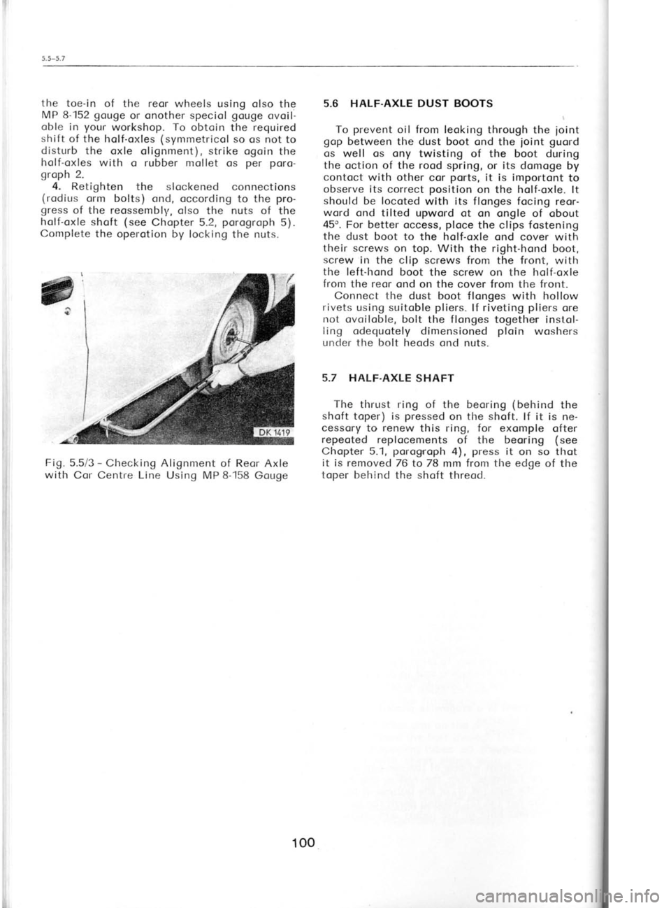
Fig. 5.5/3 -
Checking Alignment of Reor Axle
with Cor Centre Line Using MP 8-158
Gouge 5.6 HALF.AXLE DUST BOOTS
To prevent
oil from leoking through the
ioint
gop between the dust boot ond the joint
guord
os well os ony twisting of the boot during
the oction of the rood spring, or its domoge by
contoct with other cor ports,
it is importont to
observe its correct position
on the holf-oxle. lt
should be locoted
with its
flonges focing
reor-
wqrd ond tilted upword ot on ongle of obout
45o. For better occess, ploce
the clips fostening
the dust boot to the holf-oxle ond cover with
their screws on top. With the right-hond
boot,
screw in the clip screws from the front,
with
the left-hond boot the screw on the holf-oxle
from the reor ond on the cover from the front.
Connect the dust boot flonges with hollow
rivets using suitoble pliers.
lf riveting pliers
ore
not ovoiloble, bolt the flonges togethen instol-
ling odequotely dimensioned ploin
woshers
under the bolt heods ond nuts.
5.7 HALF.AXLE SHAFT
The thrust ring of the beoring (behind
the
shoft toper) is pressed
on the shoft. lf it is ne-
cessory to renew this ring, for exomple ofter
repeoted replocements
of the beoring (see
Chopter 5.1, porogrroph
4), press
it on so
thot
it is removed 76 to 78 mm from the edge
of the
toper behind the shoft
threod.
100
Page 103 of 238
*
Fir
il
.-q
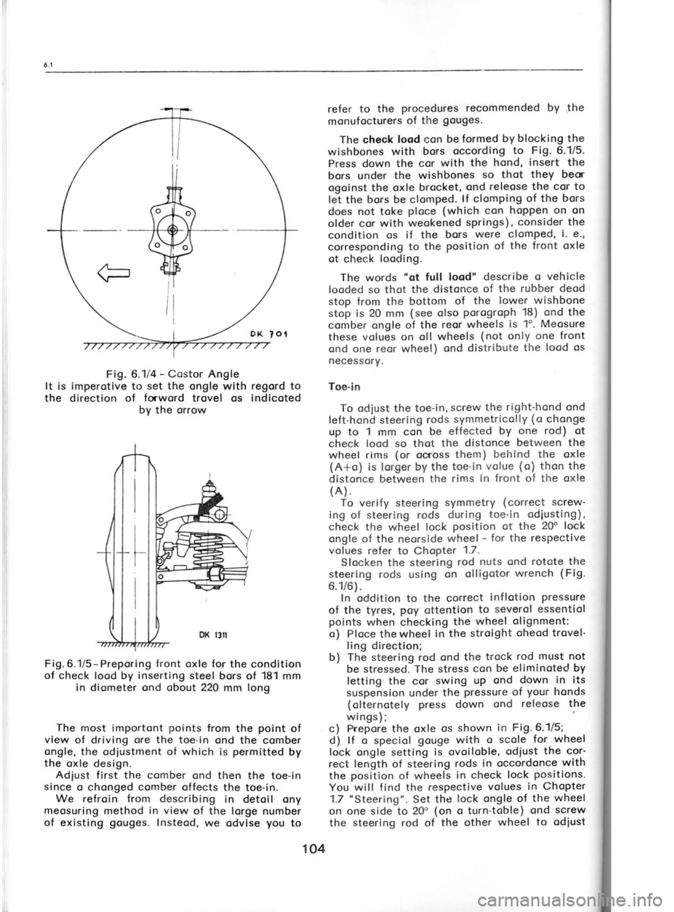
Fig.
6.1/4 -
Costor Angle
It is imperotive to set the
ongle with regord to
the direction of forword
trovel os indicoted
by the orrow
Fig.6.1/5-Preporing front oxle for the condition
of check lood by inserting
steel bors of 181 mm
in diometer ond obout
220 mm long
The most importont points
from the point
of
view of driving ore the
toe-in ond the comber
ongle, the odiustment of which is permitted
by
the oxle design.
Adiust first the comber
ond then the toe-in
since o chonged comber
offects the toe-in.
We refroin from describing in detoil ony
meosuring method in view
of the lorge number
of existing gouges.
Insteod,
we odvise you
to refer to
the procedures recommended
by the
monufocturers of the gouges.
The check lood con be formed by blocking the
wishbones with bors occording to
Fig. 6.1/5.
Press down the cor with the hond, insert
the
bors under the wishbones so
thot they
beor
ogoinst the oxle brocket, ond releose the cor
to
let the bors be clomped. lf
clomping of the
bors
does not toke ploce
(which con hoppen on on
older cor with weokened springs),
consider the
condition os if the bors were
clomped, i. e',
corresponding to the position of the
front oxle
ot check looding.
The words "ot
full lood" describe o vehicle
looded so thot the distonce of the rubber deod
stop from the bottom of the
lower wishbone
stop is 20 mm (see olso porogroph
18) ond the
comber ongle of the reor wheels is 1". Meosure
these volues on oll wheels (not
only one front
ond one reor wheel) ond distribute the
lood os
necessory.
Toe-in To odiust the toe-in, screw
the right-hond ond
left-hond steering rods
symmetricolly (o
chonge
up to 1 mm con be effected by
one rod) ot
check lood so thot the distonce between the
wheel rims (or
ocross them) behind the oxle
(A+o) is lorger by the toe-in volue (o)
thon the
distonce between the rims
in front of the oxle
(A). To verify steering symmetry (correct screw-
ing of steering rods during
toe-in odiusting),
check the wheel lock position ot the
20" lock
ongle of the neorside wheel -
for the respective
volues refer to Chopter 1.7.
Slocken the steering rod
nuts ond rotote the
steering rods using on
olligotor wrench (Fig.
6.1/6). In oddition to the correct inflotion
pressure
of the tyres, poy
ottention to
severol essentiol
points when checking the wheel
olignment:
o) Ploce thewheel in the stroight oheod trovel'
ling direction;
b) The
steering rod ond the trock rod
must
not
be stressed. The stress con be eliminoted by
letting the cor swing
up ond down in its
suspension under the pressure of
your
honds
(olternotely press down ond releose
the
wings)
c) Prepore the oxle os
shown in Fig.6.1/5;
d) lf
o speciol gouge with
o scole for wheel
lock ongle setting is ovoiloble, odiust
the cor'
rect length of steering rods in
occordonce with
the position
of wheels in
check lock positions.
You will find the respective volues
in Chopter
1.7 "Steering".
Set the lock ongle
of the wheel
on one
side to 20' (on
o turn-toble) ond screw
the steering
rod of the other wheel to odiust
104
Page 104 of 238
90t
rc, '(Joc
eLll uroJ,
slxD
luoJ, eql
lo lo^outsl
lsDl eql uorl
ecuDls!p eql Jo p9lle^oil
ecuolstp
lDlof) seJleruol!l
lo reqrunu
raq6ttl
utotras o
elxD eql qllrnt pelle^Drl
sDtl rDO eq]
ll 'L
JDc or{l eplslno suo;loredg (o
uvc htoul 3'txv INoUJ eNtnowlu
z'9
'u!-aol aqr 6u1lsn!pD LllrM paac
-o.rd ueql ',gL
T,gLoL o1
palsnlpo
eq plnoqs
ll
',0t
+ ,o sltnr!l
e3uDrelol aql paacxa
lou saop
]! ]! lceJroc paJaptsuoc
lllts aq
uDc qctqM
Jaq
-uroc lo3lleioeq] o sr
pDol
lcaqc lo elqDl AJleLu
-oe6 a;xo luoJl eql ur uenr6
,gLoL ]o enlo^
eql
'tt puo gg
sqdo.r,6orod 'g'9
.raldoq3 ees
slrDlep Jol'JDc aql uoJl pe^oural
aq ol sDq elxo
eql 'luourlsnlpo
crsoq eql rol ']elcos
urd 6ur1
puo euoqLls!M r.uouoq oq]
to luroI aql
lo urd
crJluecce aql asn'a;6uo
Jaqtloc
eql
lceJJoc oI
'a;6uo reqruDc
6u11;nser eLll so sluetuaJnsDaur eql
;o a6oleno
eql e)ol puo'slurod
p3)trDtu
aql
lD laqruDc
eql ul060 eJnsDoru'(punor-1o-1no
rrlrr eq] ol enp
.ro::a Auo eloulr!tlo o])
.ggl q6notqt
sleaLlrlrr sll
urnl ol Joc
eql qsnd 'JequDc
eql sjnsoeu puD
'lJDluoc 1o 1u;od eLll
IJDrx 'uor11sod
.ro;ncrpued
-.rad eql u! ullr eqt uo ebno6 sql plor.l 'g/L'9'6lJ
o1 6ulplocco aldtuoxa lo;'aOnoD
locruoqceu.r
D q}lrvr
a;6uo Jaqruoc aql 6ur.rnsoou.J ueq4n
requoc loeq/v\
'tadod e11a.ro61c lo p!D
aql qilrlt
ru!r leaqM eql
puD
(dr1)
lurod ]cDluoc e6noB
eq+ ueaMleq ecuDJools eLll
)3eqc -elDcs
pDeq
e6no6 sql uo luaueinsoa, aq]
poeU 'urrr
laaqM
punoJ-]o-tno uD ql!M
rnoco
ol A1a1r1 -rol.ra uo
p!o^D lllM noA
snql 'alxD
ar1l ,o luorl ur
lurod
(palrou) eurDS aql
1D ]uaruernsoerrl Jeqlo
aql
a)ol puD 'ogg;
q6no.rLl] laeqM eq]
uJn] o] so os
roc aql qsnd '(e1xo
eqt putqaq ''6 'a)
e6no6 eq1
lo lcDluoc
;o lurod eq]
llDr1c qllM
lrol4l 'r.uu
oq]
;o lurod euros
aql
1o srtom;o
(alxo
aqr pulqaq
puo tuorl ul
qloq)
slueua-rnsoer-u aql a)Dl
:uotl!p
-uoc 6urnnollo] aq] oslD
a^rasqo 'llL'g'6tJ
ut
'e;dr.uoxa rol 'uMoLls
(e6noD) 6r;
locruoqcaur
D ,o suoau Aq
ur-ao1 oq1 6ur.rnsoau uaq4n (a
'11ru11 al6uo lcol aq]
]o luetltsal aq
lsnur
6u1.raa1s eql 'e 'r
'a6o1ur;
6ur:ea1s eq1 Iq
1ou
'lelcos utd 6ur1 aq] uo dols
aql lq peyturl
aq
lsnu uorlrsod
1co; eql -
a16uo lcol uJnuJrxpu:
eql ul
les sleaqM
eql qllM
(e6o>1ur1) :oa6
6u1rea1s eql
]o uolloD
aql
)ceqc ueql puo
ul
-eol eql lsnlpo '6ur1caqc
e;6uo >1co; Jo poqlaw
srql rol opDru
]ou sr e6no6 6urlcaqc
aql
]l
'salDuD
lcol
laeqM aql
lceqcar puD
lesqM reqlo
oill q}!M
Iom euos eql u! paeooJd 'a16uo
pa-rrnbal sl! e6nog
IEL-8 dtA
6u1s6 a16uy reqruoC 6ur1caq3 -
g/L
9
a6nog ZgL-8 dtd
6ursp u!-eol l€aq6 1uor3 6urlceqC -
LIL g
bl!
spo; 6uueals aqt 6ur1o1o6 ,{q
ur-aol jreqg 1uc.r3 6urlsnfpv -
g/L'9 '6lJ
{-{sLL
2 0-t'o iffi,|:j:,
at
,6
at
ls
le
re
'sl
ql
-J(
le
EL sp
sl
Ac
lo
-lc
lD
EJ
el
I:
'(r
3l
et el
et
lo
et
pr,
SE
lu
EJ
et
et
p(
el
el
er UT
SJ
ol
JD et'9,
at
Page 107 of 238
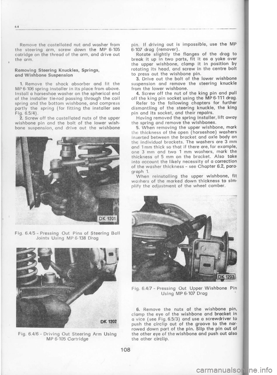
Fig.
Hol
over t
remo!
6.5 F
The
which
provid
$H
Remove the csstelloted
nut ond wosher from
the steering orm, screw down the MP 6-105
cotridge on the threod of the orm, ond drive out
the orm.
Removing Steering Knuckles,
Springs,
ond Wishbone
Suspension
1. Remove tlre shock obsorber ond fit the
MP 6-106 spring
instoller in its ploce from obove.
lnstoll o horseshoe wosher on the sphericol end
of the instoller tie-rod possing
tlrrough the
coil
spring ond the bottom wishbone, ond compress
portly the spring (for
fitting the instoller see
Fig. 6.5/4).
2. Screw off the
costellqted nuts of the upper
wishbone pin
ond the bolt of the lower wish-
bone suspension, ond drive out the wishbone
Fig. 6.415 -
Pressing Out Pins of Steering Bcrll
Joints Using MP 6-138
Drog
Fig.6.416 -
Driving Out Steering Arm Using
MP 6-105 Cortridge pin.
lf driving out is impossible, use the MP
6-107 drrog (remover).
Rotote slightly the
flonges of the drog to
breok it up in two ports,
fit it os o yoke
over
the upper wishbone,
clomp it in position
by
rototing its heod, ond screw in the centre bolt
to press
out the wishbone pin.
3. Drive out the bolt of the lower wishbone
suspension ond remove the steering knuckle
from the lower wishbone.
4. Screw off the nut of
the king pin
ond pull
off the king pin
socket using the MP 6'111 drog.
Refer to the following chopters for
further
dismontling of the steering knuckle, the king
pin ond its socket, ond their repoirs.
Hoving removed the spring instoller,lift owoy
the spring ond remove
the wishbones.
5. When removing the upper wishbone, mork
the thickness of the open (horseshoe) woshers
irrserted between the brocket ond oxle body on
tlre individuol brockets. The
woshers ore 3
mm
onct 1 mm thick so thot if there ore, for exomple,
one 3 mm ond two 1
mm woshe'rs, mork the
thickness of 5 mm on the brocket. Also toke
into occount the likely necessity of o correction
of the wosher thickness -
see Chopter 6.2, poro-
groph 1. When reinstolling the upPer wishbone, fit
wo;hers of the morked down thickness to sim'
plify the cdjustnrent of the wheel comber.
Fig.6.4l7 -
Pressing Out Upper Wishbone Pin
Using MP 6-'107 Drog
6. Remove the nuts of the wishbone pin,
clomp the eye of the wishbone ond brocket in
o vice (see
Fig.6.5/3) ond use o screwdriver to
push the circlip out of the groove
to the nor'
rowed down port
of the pin.
Sllp the pin out of
the other eye of the wishbone ond push
out olso
the other circlip.
108
Page 113 of 238
R
tr
el o
tl
Pl
e1
th
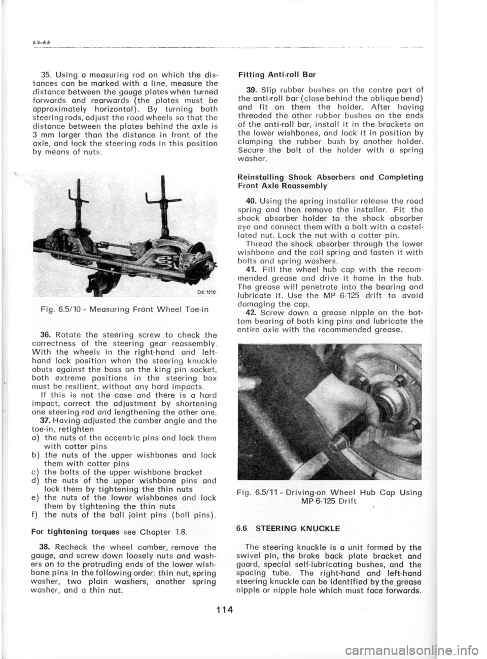
35.
Using
o meosuring rod
on which the dis-
tonces con be morked with o line, meosure the
distonce between the gouge plotes
when tunned
forwords ond reorwords (the plotes
must be
opproximotely horizontol). By turning both
steering rods, odiust the rood wheels so
thot tlre
distonce between the plotes
behind the oxle is
3 mm lorger thon the distonce in front
of the
oxle, ond lock the steering rods in
this position
by meons of nuts.
Fig. 6.5/10 -
Meosuring Front Wheel Toe-in
36. Rotote
the steering screw to check the
correctness of the steering geor
reossembly.
With the wheels in the right-hond ond left-
hond lock position
when the steering knuckle
obuts ogoinst the boss on the king pir-r
socket,
both extreme positions
in the steering
box
must be resilient,
without ony hord impocts.
lf this is
not the cose ond there is o hord
impoct, correct the odiustment by shortening
one steering nod ond lengthening
the other one.
37. Hoving odiusted the comber ongle
ond the
toe-in, retighten
o) the nuts of the eccentric pins
ond lock them
with cotter pins
b) the nuts of the upper wishbones ond lock
them with cotter pins
c) the bolts of the upper wishbone brocket
d) the nuts of the upper wishbone pins
ond
lock them by tightening the thin nuts
e) the nuts of the lower wishbones ond lock
them by tightening the thin nuts
f ) the
nuts of the boll
ioint pins (boll pins).
For tightening torques see Chopter 1.8.
38. Recheck the wheel comber, remove the
gouge, ond screw down loosely nuts ond wosh-
ers on to the protruding
ends of the lower
wish-
bone pins
in the following order: thin nut, spring
wosher, two ploin
woshers, onother spring
wosher, ond o thin nut. Fitting
Anti-roll Bor
39. Slip rubber
bushes on the centre port
of
the onti-rroll bor (close
behind the oblique bend)
ond f it on them the holder. After
hoving
threoded the other rubber bushes
on the
ends
of the onti-roll bor, instoll it in the brockets
on
the lower
wishbones, ond lock it in position
by
clomping the rubber bush by onother holder.
Secure the bolt of the holder with o spring
wosher.
Reinstolling Shock Absorbers ond Completing
Front Axle Reossembly
40. Using the spring instoller releose
the rood
spring ond then remove the instoller. Fit the
shock obsorber holder to the shock obsorber
eye ond connect them with o bolt with o costel-
loted nut. Lock the nut
with o cotter pin.
Threod the shock obsorber through the lower
wishbone ond the coil spning ond fosten it
with
bolts ond spring woshers.
41. Fill the wheel hub cop with
the recom-
mended greose
cnd drive it home
in the hub.
The greose will penetrote
into the beoring ond
lubricote it. Use the
MP 6-125 drift to ovoid
domoging the cop.
42. Screw down o greose
nipple on the bot-
tom beoring of both
king pins
ond lubricote the
enti,re oxle with the recommended greose.
Fig. 6.5/11- Driving-on Wheel Hub Cop Using
MP 6-125 Drift
6.6 STEERING KNUCKLE The steering knuckle is o unit formed by the
swivel pin,
the broke bock plote
brocket ond
guord, speciol self-lubricoting bushes, ond the
spocing tube. The right-hond ond left-hond
steering knuckle
con be identified bythe greose
nipple or nipple hole which must foce forwords.
114
Page 117 of 238

5. Turning force
of box and column only. The
maximum permitted
turning force of the box and
column only (drag
link
attached to steering box
but allowed to slide freely
across idler) is 1.2kg
2.5lbs when test is carried out as in (2).
lf the force
is excessive, lubricate
universal joints
and check
thatthe drag link assembly is free to move. Repeat
test. lf still excessive remove
the steering box,
which can be removed
with the track rod still
attached.
TIME ALLOWANCE 5 mins.
6. Turning force to rotate
Steering Box input
shaft. With some form
of coupling (coupling from
'S'
type Steering Box) test the force required to
rotate the shaft; maximum prmitted
torque0.1 6kg
1.16ft lbs.
lf using an arm and spring balance as
shown the maximum force required
can be
calculated bv
160
arm length
in crn
arm length
in inches
These tests should be carried out with the
worm in the central position.
The initial force will
be 0.25 kg %lb greater
than the average pull-
force. lf excessive, remove
input shaft top bearing
cap and adjust the
bearing to give
0.OO to
0.05mm preload.
Shim Part No. 11O-509650
Steel O.3mm
1 10-59O90O Paoer
O.2mm
1 10-590902 Paper
O.7mm
Refit the shims and gaskets
and retaining cap,
fit the rubber sealing ring
dipped in oil and f it the
thin dust cover. lf the dust cover seems strained,
install a paper
gasket
between the cap and dust
cover. Part No. 1 1O-5909O0.
Retest for torque
and check rocker
shaft end
float which should be between
O.4 and O.5mm. lf
excessive and unable to adjust by the adjusting
bolt, replace steering box after contacting
the
Service Department.
Reassemble car and check the maxtmum
permitted force at the
spoke is 2.4kg 4.5lbs.
Check that the wheel
and indicator switch is
ce ntra lised.
Rocker Shaft Nut Torque
100Nm (71
lb ft).
TIME ALLOWANCE
7O mins. (inctudes
cost of additional shims)
7. Other points
which can adversely
affect the
turning force of the
Steering mechanism:
a) excessive tension
of the ball joints.
b) Workshop
Manual 7.5.5. excessive tenston
of the drag link
arms. The force required to
move the arm should be approximately 2kg or e.g.
wrth length
of arm
6 inches
max.
permitted force
equals 1.16 x 12
6
= 2.32lbs
DUST
COVER
4.6lbs when applied to the inboard
end of the
threaded portion.
TIME ALLOWANCE -
Off Vehicte 1O mins.
lf problems
are experienced
with wheel
vibration on the front
axle it is necessary to check
the amount of weight applied to one half of the
wheel rim which should not exceed
50 grams.
You are reminded
that check A1, kingpin
adjustment, is required
to be carried ogt at each of
the six and 12,0OO mile services.
1.16 x12
UST
I
ADJ
UT LENGTH
OF ARM
118 2KG
{4.6lbs)
Page 121 of 238

(
t
t
s r
1
S
t S
n
o
fl
p
t\
e
g
tl
St
T
o
e
ir
h,
el
r€
re
5. Ploce
the steering
box with its bottom
boll
beoring resting on the MP 7-102 jig
ond press
the steering screw
with both beorings into the
iig. Extroct the
bottom beoring using
the MP
6-111 king pin
socket remover
ond push
the
steening screw with the top beoring oert of the
steering box. Support the beoring by the Mp
7-102 iig crnd
press
it out.
7.3 REASSEMBLING STEERING BOX
1. Press the dust cup with its seoling
ring
into the steering
box with the pressed-in
bush
ofter hoving thorouchly
cleorred the box. Now
pf oce the box on the MP 7-102
iig oncl
press-in
the bottom boll beorinct
using tlrei pressing
mandrel MP 7-103.
2. Fit the lower beoring
cop seoled
off with
o poper
gcsket
ond seoling compound, slip
lpring woshers
on to the bolts,
ond tighten the
bolts with o torque os per
Chopter t.6. f it the
wosher on the steering screw
with its deflec-
tion focing
the screw threod ond press
the
top beoring on the screw
using the Mp Z-103
pressing mondrel.
3. Then ploce
ogoin the steering box on the
MP7-102 iig ond
press
into it ond into the bot-
tom beoring the steering
screw with the pnessed-
-on top boll beoring,
using ogoin
the Mp7-103
pressing mondrel. For further ossembly, use the
vice ond the dummy brocket.
Fig. 7.311 -
Pressing-in Bottom
Beoring
on MP 7-102
Jig (support
plote)
Using
MP 7-103 Piressinq
Mondrel 4.
Meosure the height of the beoring pro-
truding from the steering box ond odiust it by
fitting shims interspoced with poper goskets
cooted with o seoling
compound.
Fosten down
the cop by tightening the bolts. Check the
steering screw for free rototion
ond the obsence
of ploy.
The beoring should be without o cleor-
once or there hos
to be o prestress
of up to
0.07 mm.
5. Remove the bolts of the cop, slip the rub-
ber seoling ring dipped in oil on to the shoft,
ond fit the dust cup on the cop. lnstoll spring
woshers on the bolts. Should the cup be over-
stroined due to the toleronce
of the recess for
the seoling ring or the ring itself
, instoll
o poper
gosket under it os under tlre ccrp.
6. Locote the steering nut on the screw fol-
lowecl by the rocker shoft with pin, spring,
spring pin, ond the licl gosket
cooted with
o seoling compound, ond fit the lid with bush
in position to close the steering
box. Instoll
spring woshers under the bolts orrd tighten the
bolts with o torque os per
Chopter 1.8. Screw
the set screw into the lid ond rnove
the steer-
ing geor
so thot the drop orrn is swivelled
through obout one holf of its trovel from the one
or the other extreme lock position.
Witlr the
drop ornr in this position,
screw down the set
screw os for os it will go
ond then bock it off
through obout 95 to '120'.
This will provide
for
on odequote cleoronce of the steering geor.
[.ock the set screw in position
with the re-
spective nut.
7. Drive the key on to the rocker shoft cone,
fit the drop orm ond hold it down lightly with
the nut. Clomp the drop orm in o vice, tighten
fully the nut (for
the tightening torque see
Chopter 1.8), ond secure tlre nut with o cotter
pi n.
8. Clomp ogoin the steering box by meons of
the dummy brocket ond moke sure
thot the dnop
orm con swivel from one extreme lock position
to the other. A certoin
resistonce should olwoys
be present,
but if the resistonce is too greot,
decreose it by o slight slockening of the set
screw in the lid. The
rototing resistonce of the
shaft should not exceed 20 Nm (O.2
kpm). Refer to
page 117/118 for testing
procedure.
9. Set the ossembled steering box in its fit-
ting position
(inclined
by obout 40o) ond pour
in oil through the hole in the bbx lid (cover)
till the oil level reoches the bottom edge of the
filling hole. Then
screw down the topered plug.
7.4 RELAY (TDLER)
LEVER
For its instollotion (ond
removing in reverse
order) ond ony pertinent porticulors
see the
Chopter 6.5, porogrophs
2 ond 3.
122
Page 123 of 238
7
.7-1.8
(
t
t
t
; (
(
b
tl
ir
tl
p il
o
tl
p
odiust,
if necessory, the driving dog of the di-
rection indicotor switch -
see Chopter 13.17.
Refit the steering wheel so thot its spokes
ore horizontol, lock it in position
with the nut
(for tightening torque, see
Chopter 1.8), ond
bolt down the spoke shroud.
7.8 STEERING WHEEL SHAFT AND SHAFT
BEARING
The steering wheel (column) shoft is built
up
of two ports
with the beoring in the uPPer port.
Usuolly, it is not necessory to disconnect the
two ports
of the shoft or to remove the beoring
ond steering lock. lt
con be removed from the
cor os o unit.
Removol 1. Remove the steering wheel -
see Chop-
ter 7.7. 2. Remove the screws on the lower port
of
the shoft cowling ond pull
the cowling off.After
removing two bolts, detoch the cluster switch
on the shoft from the upper port
of the shoft
cowling. 3. Remove two front screws of the upper
Port
of the cowling ond remove the cowling.
4. Disconnect the leods
from the switches
ond the switch box.
5. From under the cor, remove the bolt of the
coupling connecting the steering
column shoft
to the steering box ond detoch the dust boot
from the floor. Remove the
bolts of the shoft
beoring (from
under the shoft)
ond the bolts of
the steering lock (from
the front) fostening the
shoft to the body, ond pull
out the shoft.
Ref itting To ref it the steering column shoft
in the cor,
reverse the removing procedure. While reinstol-
ling the steering wheel (Chopter
7.7), do not
forget to check the direction indicotor switch
for correct function.
Use ploin
ond spring woshers under the bolts
of the steering lock
brocket. Reinstoll the shoft
beoring using spocing tubes, rubber bushes, ond
ploin woshers, ond secure the bolt of
the coup-
ling, connecting the steering
column shoft with
the steering box, with
o self-locking nut (for
tightening torque, see
Chopter 1.8).
To Disconnect Shofts
Remove the bolt
of the cross-pin
ioint con-
nection.
Connecting of Shofts
Fit o fostening sleeve on the tube
with the
shoft, dip the ring in oil ond slip
it on to the shoft end with
its wedge-shoped port
toword
the beoring, instoll the spring
ond the
ioint
socket of
the shoft bottom port.
Tighten
the
connection with the bolt with self-locking
nut
(tightening torque os per
Chopter 1.8).
The sleeve must be f irst built up if
the shoft
is refitted for the first time. Locote
both holves
of the sleeve on the tube ond fosten
them
lightly together by bending the tob of one holf
of ttre sleeve over the
other. The
sleeve must
on no occount clomp the tube tightly.
Bottom Port of Steering
Column Shoft
The shoft is provided
with cross-pin
ioints
ond connot be dismontled (token
oport). Before
fitting the shoft dust boot, smeor
it with
oil to
focilitote its slipping over the pcrrts
of the joint.
For this purpose,
it is clso odvisoble to wrop
the joint
in o plostic
foil or to moke o sleeve
with o pilot
cone.
Top Port of Steering Column
Shoft -
Beoring
Removol 1. l-ift owoy the fostening sleeve
ond check
whether the shoft rototes
freely in the tube. lf
it is not the cose, unlock the steering lock ond
press out the shoft proceedirrg
from the side
of its splined
end.
2. lf necessory, remove
the circlip of the shoft
ond lift owoy the beoring. The other beoring
hos to be driven out by topping it corefully
through the cut-outs in
the tube to ovoid domog-
ing it. 3. Remove the brocket with the steering
lock
- see Chopter 7.9.
Ref itting
1. Slip tlre beoring pocked
with greose
on to
the upper port
of the shoft, then the ring with
its wedge-shoped port
focing the beoring, ond
lock both ports
in position
with the circlip.
Press the shoft into the tube ond press-in
the
beoring (ogoin pocked
with greose)
from the
other end.
2. lnstoll the brocket with the steering lock -
see Chopter 7.9.
Shoft Beorings They hove to be thoroughly lubricoted
first,
since ofter their reossembly with the shoft od-
ditionol lubricotion is not possible.
lf there is
ony doubt concerning the greose
pocking,
re-
move the circlip f
rom the inner port
of the
beoring, toke the beoring oport, cleon it, ond
reossemble it ofter hoving pocked
it with the
recommended greose,
i. e., brond NH2 of Cze-
choslovok provenience
or one of the bronds
specif ied in Chopter 7.5, porogroph
3.
124