1980 SKODA 120 LSE oil
[x] Cancel search: oilPage 161 of 238
1
1
1
1
1
1:
1r
1l
't,
1',
1:
1:
1l?
ffi{,
ll
---r---
i
fdll
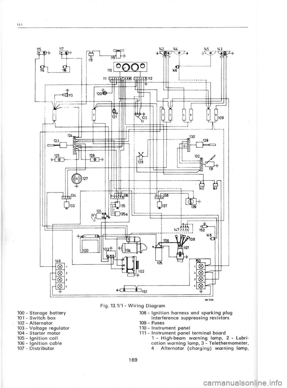
100 -
Storoge botteny
101 -
Switch box
102 -
Alternotor
103 -
Voltoge regulotor
104 -
Storter motor
105 -
lgnition coil
106 -
lgnition coble
107 -
Distributor 115
113
'l7s:,!--,t
ir
rl
tl
tl
t|- -
- --
- - -- - - --- --- -l
116 i
I
I
L--_-___---__ I
Fig. 13.111 -
Wiring Diogrom
108 -
lgnition horness ond sporking plug
interference suppressing resistors
109 -
Fuses
'110 - Instrument ponel
111 -
Instrrument ponel
terminol boord
1 -
High-beom worning lomp, 2 -
Lubri-
cotion worning lomp, 3 -
Telethermometer,
4 Alternotor (chorging)
worning lomp,
169
Page 165 of 238
'i
iiiI 14. Fuse box
Centrol connection of conductors -
do not
seporote them from the bunch!
15. Direction indicotor switches, dip switch,
and horn switch
eight-pole terminol
boord
six-pole terminol boord
16. Porking light switch ond high beom feeder four-pole terminol boord
17. Switch box femole connectors 5.5 with symbols "15",
"30", ond '50"
to be
connected to symbols
"15u, "30', ond '50"
on the switch box
18. Instrument ponel
ten-pole terminol boord
six-pole terminol boord
eorthing coble with lug
'19. Heoter switch
four-pole terminol boord
20. Switch of disobility lights
six-pole terminol boord
21. Door switch, right-hond
green -
femole connector 5.5
22. Dome light,
right-hond
green -
femole connector 5.5
red -
femole connector 5.5
23. Stop switches
forked (yellow) -
femole connectors 5.5 .
red -
femole connector 5.5
white -
femole connector 5.5upper ond lower
switch
upper switch lower switch
24.Fuel gouge block -
femole connector 5.5
yellow -
femole connector 5.5
blue -
femole connector 5.5
to be connected to the respective pins
(blodes) of the some colour of the fuel gouge
25. Storter motor, reversing
lomp switch
conductors with lugs stater motor moin
terminol boord
storter motor
control switch
green -
femole connectors 5.5 heodlomp switch
26. Oil pressure
gouge,
thermometer, corburettor
iet seporotor
green -
femole connector 5.5 yellow
-
femole connector 5.5
green - telethermometer
primory element
femole connector 7.
corburettor
iet seporotor
27. lgnition coil, voltoge regulotor, olternotor,
tochometer
conductor with femole connector ond
bronching lug
femole connector-regulotor terminol 15/54
lug -
ignition coil terminol 15
blue -
femole connector 5.5,
symbol "R"
. regulotor terminol "R"
yellow -
femole connector 5.5,
symbol "M"
regulotor terminol "M"
blue -
connector "R"
. olternotor terminol "R"
yellow -
connector "M".
olternotor terminol "M"
lug terminol "+B"
conductor with
lug ignition coilterminol "1"
(tochometer operotion
)
28. Toil lomp cluster, right.hond
yellow -
femole connector 5.5 toil light
block -
femole connector 5.5 direction indicotors
red -
femole connector 5.5 stop light
green -
femole connector 5.5 reversing lomp
29. Licence plote light
conductors with femole connectors 5.5
30. Toil lomp cluster, left.hond
se point
28.
b) Connection
of free conductors
1. Storoge bottery
bottery coble positive
(*)
terminol -
storter motor
bottery eorthing strip negotive (-)
terminal -
bodywork (eorthing conductor)
2. Engine engine eorthing strip (fostening
lug) -
engine cross beorer (eorthing conductor)
3. Distributor speciol coble from distributor to
ignition
coil; end with interference suppressing
terminol to distributor
coble from distributor to ignition coil
terminol "1"
cylindricol
(pin)
connector
pressure gouge172
Page 171 of 238
junction
with the olternoto,r occording to
Chop-
ier 13.3 ond mointoining
o constont voltoge of
tlre power
supply set within the
entire ronge
of
service speeds.
Tlre voltoge regulotor
is instolled orr the body
cross beorer, to
the right of the engine ond
beside the ignition coil.
To focilitote hondling
of its leods' especiolly
the occess to their
connections, it
is recom-
rrrended to remove the regulotor fostening
screws. For disconnecting procedures,
see
Chopter 13.3 "Alternotor
lnstollotion ond Gen-
erol lnstructions".
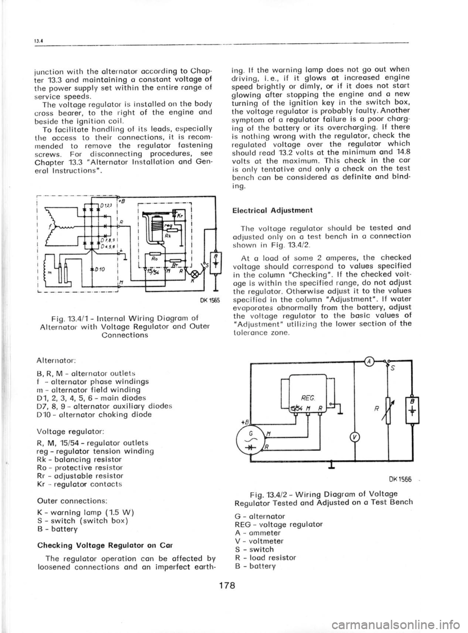
DK 1565
Fig.13.411- Internol
Wiring Diogrom of
Alternotol with
Voltoge Regulotor ond
Outer
Connections
Altenrotor: B, R, M -
olternotor outlets
f -
olternotor phose
windings
m -
olternotor field winding
D1,2,3, 4, 5, 6 -
moin diodes
D7, 8,9 -
olternotor ouxiliory diodes
D10 -
olternotor choking diode
Voltoge regulotor:
R, M, 15/54 -
regulotor outlets
reg -
regulotor tension winding
Rk -
boloncing resistor
Ro -
protective resistor
Rr -
odiustoble resistor
Kr -
regulotor contocts
Outer connections: K -
worning lomp (1.5
W)
S -
switch (switch
box)
B -
bottery
Checking Voltoge Regulotor
on Cor
The regulotor operotion con be offected by
loosened connections ond on imperfect eorth- ing.
lf the wsrning lomp does not go
o.ut when
driving, i. e., if it glows
ot increosed engine
speed brightly or dimly,
or if it does not stort
glowing ofter stopping
the engine ond
o new
iurning of the ignition key in
the switch box,
the voitoge regulotor
is probobly
foulty. Another
symptom of o regulotor
foilure is
o poor
chorg-
irrg of tlre bottery or its
overchorging.. lf there
is nothing wrong with the regulotor, check the
reguloted voltoge over the regulotor which
slrould reod 13.2 volts ot the
minimum ond 14.8
volts ot the moximunr. This check
in the
cor
is only tentotive ond only
o check on
the test
bench'con be considered os definite ond
bind'
i ng.
Electricol Adiustment
The voltoge regulotot- should be tested
ond
odjusted only on o test bench
in o connection
slrown in Fig. 13.412.
At o lood of some
2
onrperes, the checked
voltoge should correspond to
volues specified
in the column "Checking".
lf the checked volt-
oge is within the specified ronge, do
not odiust
the regulotor. Othenwise odiust it to the volues
specified in the column "Adiustment".
lf woter
evoporotes obnormolly from the bottery, odiust
the voltoge regulotor to the bosic volues of
"Adiustment" utilizing the lower section of
the
toleronce zone.
Fig.13.al2 -
Wiring Diogrom of
Regulotor Tested
ond Adiusted on
o
G -
olternotor
REG -
voltoge regulotor
A -
ommeter
V -
voltmeter
S -
switch
R -
lood resistor
B -
bottery DK
1566
Voltoge Test Bench
178
Page 173 of 238
I
I
t
b
c ll
e
c
tl
d n
tN'
>
\'
J I
(Il
qt3
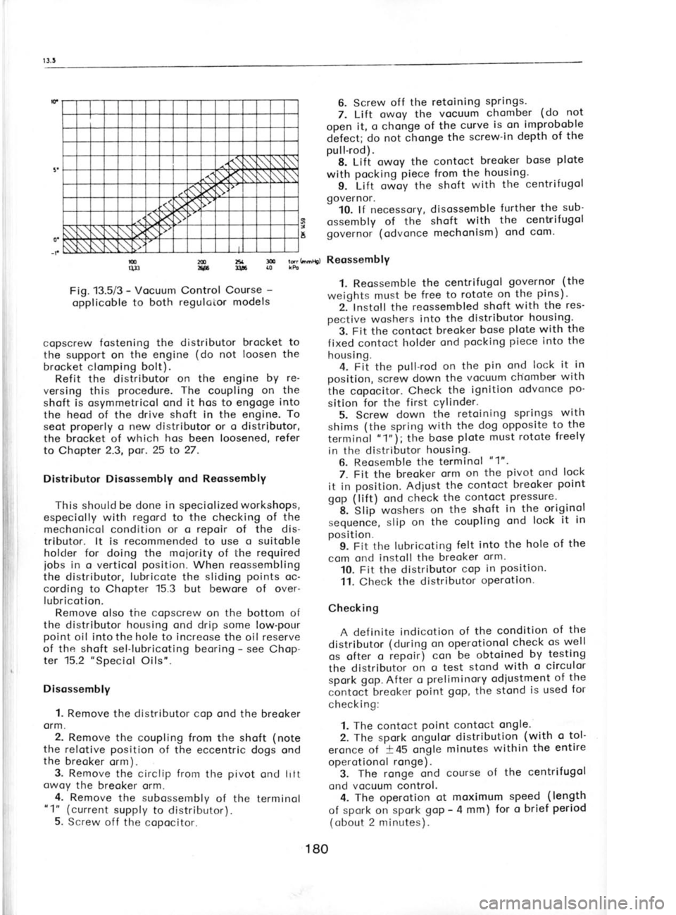
Fig. 13.5i3 -
Vocuum Control Course -
opplicoble to both
regulotor models
copscrew fostening the distributor brocket to
the support on the engine (do
not loosen the
brocket clomping bolt).
Refit the distributor on the engine by
re-
versing this procedure. The
coupling on
tlre
shoft is osymmetricol ond it hos to engoge into
the heod of the drive shoft in the engine. To
seot properly
o new distributor
or o distributor,
the brocket of which hos
been loosened, refer
to Chopter 2.3, por.25
to 27.
Distributor Disossembly ond Reossembly
This should be done in speciolizedworkshops,
especiolly with regord
to the checking of the
mechonicol condition or o repoir
of the dis-
tributor. lt is recommended
to use o suitoble
holder for doing the moiority of the required
iobs in
o verticol position.
When reossembling
the distributor, lubricote
the sliding points
oc-
cording to Chopter 15.3
but bewore of over-
lubricotion.
Remove olso the copscrew
on the bottom of
the distributor housing ond drip some low-pour
point oil into the hole to increose the oil reserve
of the shoft
sel-lubricoting beoring -
see Chop-
ter 15.2 "Speciol
Oils".
Disossembly 1. Remove the distributor cop ond the breoker
orm.
2. Remove the coupling from the shoft (note
the relotive position
of the eccentric dogs ond
the breoker
orm).
3. Remove
the circlip from
the pivot
ond litt
owoy the breoker orm.
4. Remove
the subossembly
of the terminol
"1" (current supply to distributor).
5. Screw off the copocitor. 6. Screw
off
the retoining springs.
7. Lilt owoy the vocuum chomber (do
19t
open it, o chonge of the curve is on.improboble
d'efect; do not chonge the screw-in depth
of the
pull-rod).
' 8. Lift owoy the contoct breoker
bose plote
with pocking piece from
the housing.
g. Litt owoy the shoft with the
centrifugol
governor. -
10. lf necessory, disossemble further
the sub'
ossembly of the shoft with the centrif
ugol
governor (odvonce mechonism) ond
com.
l?;h.',0, ReossemblY
1. Reossemble the centrifugol governor
(the
weights must be free
to rotote on the pins).
2. lnstoll the reossembled shoft
with the res'
pective woshers into
the distributor housing.
3. Fit the contoct breoker bose plote
with the
f ixed contoct holder ond pocking
piece into the
housing. 4. Fit the pull-rod on
the pin
ond lock it in
position, screw down the vocuum chiomber with
the copocitor. Check the
ignition odvonce po-
sition for the first cYlinder.
5. Screw down
the retoining springs
with
shims (the
spring with
the dog opposite to
the
terminol "1"i;
the bose plote must
rotote freely
in the distributor housing.
6. Reosemble the terminol "1".
7. Fit the breoker orm
on
the pivot
ond lock
it in position. Adiust the contoct breoker point
gop (lift) ond check the
contoct
Pressure'
"
if. 'Stip
woshers on
the shoft in
the originol
sequence, slip on the coupling ond
lock
it in
position^ 9. Fit the lubricoting felt
into the hole of
the
com ond instoll the breoker orm.
10. Fit the distributor cop
in position.
11. Check the distributor operotion.
Checking A def inite indicotion of the condition of
the
distributor (during on operotionol check
os
well
os ofter o
repoir) con be obtoined by testing
the distributor on
o test stond with
o circulor
spork gop.
After o preliminory
odiustment of
the
contoc-t breoker point gop,
the stond is
used for
check i ng:
1. The contoct point
contoct ongle.
2. The spork ongulor distribution (with o
tol-
eronce of -+45
ongle minutes within
the entire
operotionol ronge).
3. The rongJ ond course of the
centrifugol
ond vocuum control. 4. The
operotion ot
moximum speed (length
of spork on spork goP -
4 mm) for o
brief period
(obout 2 minutes).
180
t
5
2tD zsa !l!
F llti
rc
Page 175 of 238
I
I
I
s
I
I
I
t
(
(
t
l
,
t
T c
R
L D
v Ir
1' 2
3
orotely
(
screen the other one) . With lef t
directionol heodlomps,
the borderline deviotes
towords the other
side.
lf the heodlomps ore neorer to the woll thon
the soid
5 metres, decreose the meosure indi-
coting the
deviotion of the light ond
dorkness
bordeiline from the
height of the heodlomps
obove the ground in the
direct proportion to
the
decreose of
tfre distonce, for
exomple when
plocing the cor 2.5 metres
from the woll, de-
creose the deviotion bY holf.
Light proiections "A"
ond "B"
correspond to
the spocing of heodlomPs on
the cor ond they
hove the following dimensions:
Heodlomps, dio. 160
mm 1,030
mm
Duol heodlomps, dio.
130 mm 1,114
mm
Auxiliory heodlomps, dio.
130 mm 790 mm
When odjusting the heodlomps, the cor must
be empty ond the
tyres must be correctly in-
floted. Hologen heodlomps should
not be left
switched on for too long o period os they build
up heot if not cooled by heod-on
oir blost when
driving. For lhe odiustment of
heodlomPs ore intended
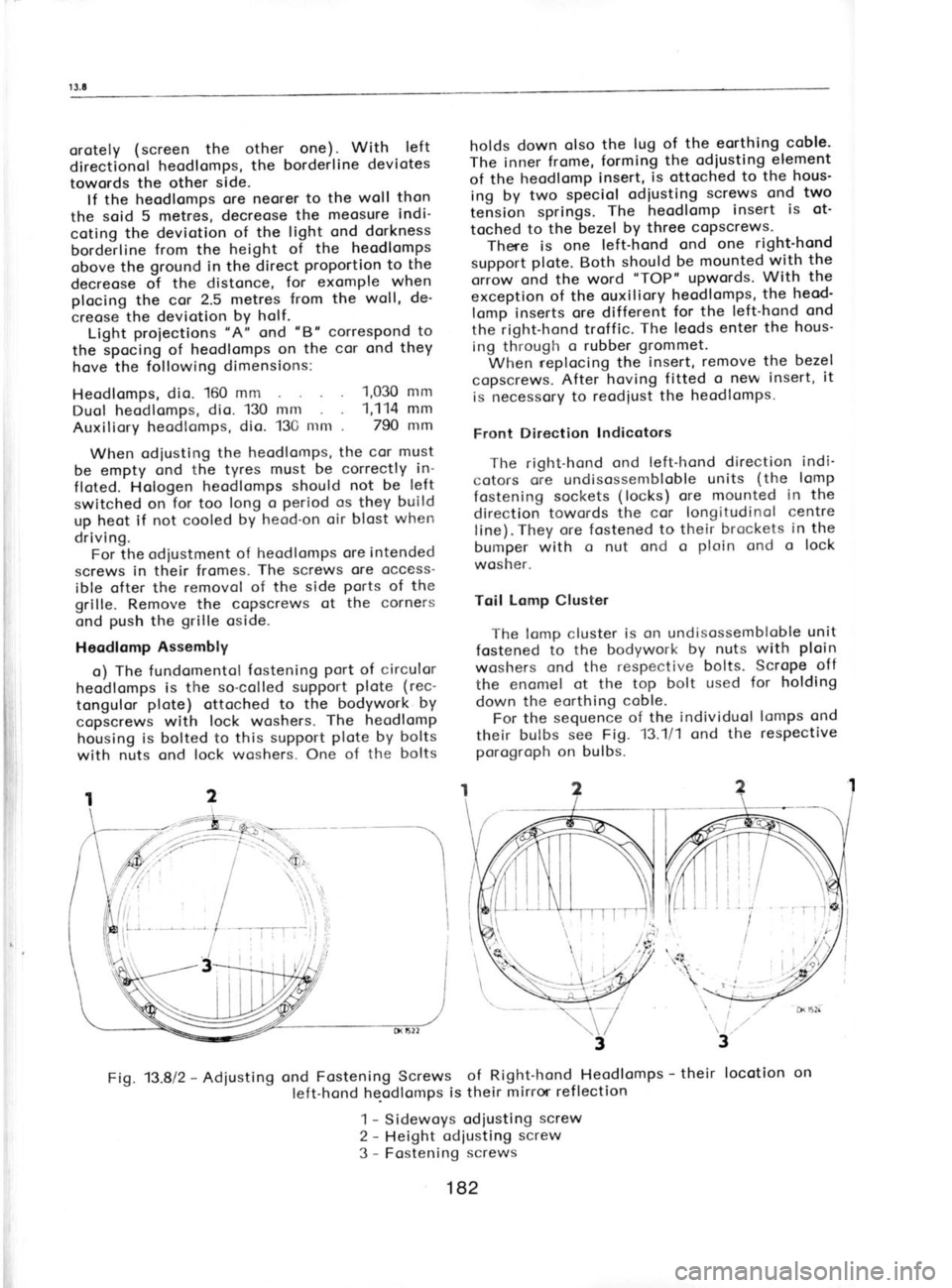
screws in their fromes. The screws
ore occess'
ible ofter the removol of the side ports
of the
grille. Remove the copscrews of the corners
ond push
the grille
oside.
Heodlomp Assembly
o) The fundomentol fostening
Port of
circulor
heodlomps is the
so-colled support plote
(rec-
tongulor plote)
ottoched to the bodywork by
copscrews with lock woshers. The
heodlomp
housing is bolted to this suPPort plote by bolts
with nuts ond lock woshers. One of the bolts holds
down olso the
lug of the eorthing coble-
The inner frome,
forming the
odiusting element
of the heodlomp insert, is ottoched
to the
hous'
ing by two speciol odiusting screws
ond two
tension springs. The heodlomp insert
is ot'
toched to
the bezel by
three copscrews.
There is one left-hond ond
one right-hond
support plote.
Both should
be mounted with the
oriow ond the word "TOP"
upwords. With
the
exception of the ouxiliory heodlomps, the
heod'
lomp inserts ore different for
the left-hond ond
the right-hond troffic. The leods
enter the hous-
ing through o
rubber grommet.
When r-eplocing the insert, remove
the bezel
copscrews. After
hoving fitted o new insert, it
is necessory to reodiust the
heodlomps.
Front Direction Indicotors
The right-hond ond
left-hond direction indi-
cotors ore undisossembloble units
(the
lomp
fostening sockets (locks) ore
mounted in the
direction towords the cor longitudinol centre
line). They ore fostened to their brockets in the
bumper with o nut ond o ploin ond
o lock
wosher.
Toil Lomp Cluster
The lomp cluster is on undisossembloble unit
fostened to
the bodywork by
nuts with ploin
woshers ond the
respective bolts.
Scrope off
the enomel ot the
top bolt used for holding
down the eorthing coble.
For the sequence
of the individuol lomps ond
their bulbs see Fig. 13.111 ond the respective
porogroph on bulbs.
Fig. 13.812 -
Adiusting ond
Fastening Screws of Right-hond Heodlomps -
their locotion
on
left-hond he-odlomps is their
mirror ref lection
1 -
Sidewoys odiusting screw
2 -
Height odiusting screw
3 -
Fostening screws
182
Page 179 of 238

(
1
z
Strike the
slip-over ring off the circlip
(towords the motor windlng). Open the circlip
ond pull
it off the shoft together with the re-
leosed ports.
8. lf necessory, re-turn the commutotor ond
scrope or mill out the insulotion between the
lominotions. "Mikonit"
should be 0.4 to 0.8 mm
below the octive surfoce.
Note: The
switch connot be further token
opat. lf
defective, lt hcs to be reploced with
o new one. When cleoning ports
of the storter
motor, do not dip the ormoture or the pinion
with the idler into petrol
or onother degreosing
ogent.The some opplles to the end shieldswith
beorings. By dipping them in o degreosing
ogent, the beorings become procticolly
worth-
less"
Storter Motor Reossembly 1. Lubricote the hellx of the ormoture shoft
with greose -
see Chopter 15.2 'Lubriconts
of
foreing mokeu ond fit the pinion
with the idler
ond the slip-over ring in posltion.
Fit the
circlip
into the groove
in the shoft, ond drive the slip-
on ring over it. The pinion
with the idler must
move freely olong the shoft.
2. Slip the respective
woshers on the shoft in
their originol sequence (corrier
ring, distonce
ring, fibre ring, distonce ring) ond insert the
ormoture with the engoging lever
into the drive
end shield. 3. Suspend the switch
ormoture into the
pre-engoging lever ond bolt down the switch
lightly. Fit the lever pin
into the drive
end
shield ond lock it in position
with the retoiner.
4. Tighten the copscrews of the switch
ond
fit the stotor on the drive
end shield.
5. Instoll the respective
woshers into
the
commutotor end shield in
their originol se-
quence (the dished wosher with its centre
focing the shield, then the ploin
wosher, the
toothed wosher, ond the drive wosher).
6. Fit the commutotor end shield with lifted
brushes on the shoft (in
the position
occording
to the recess
for the excitotion outlet ond the
notch) ond screw in the clomping bolts.
7. Instoll the brush interconnecting strip ond
bolt it down together with the field winding
outlets to the positive
brush holders, lower the
brushes. 8. Fit the Insuloting strip in position
ond bolt
down the cover. 9. Test the storter mottr.
Diognosing Storter Motor Defects in Cor
o) lf the storter motor refuses
to operote, look
first for on interrupted connection between
the bottery ond
the storter
motor, the engine
eorthing ond the storter
motor, or the engine
eorthing ond the bottery. lf these connec-
tions ore in order (current
flows to the ter' DK
1575
Fig. 13.10/3 -
Storter Motor Testlng Connection
minols u30"
ond "50"
with switched on
ignition), stort looking for o foilure of the
storter motor switch. Even in this instonce,
the couse con be o fully dischorged or foulty
bottery.
b) lf the storter motor
continues running
even
ofter the ignition key hos been switched in
the switch box from the position "START",
it hos to be stopped without ony deloy by
disconnecting the bottery (using
its eorthed
pole).
c) lf the storter motor hos no power
to cronk
the engine, stort with switched-on heod-
lights. A
morked dimming indicotes c poorly
chorged bottery.
Tentotive Checking of
Storter Motor
Outside Cor
Connect the terminol "30'of
the storter
motor to o properly
chorged bottery ond incor'
porote on ommeter with o wide
meosuring ronge
into the circuit -
see Fig. 13.10/3.
Stort the
engine (feed
current to the terminol "50").
The
volue of the current ot idling speed must
not
exceed 65 omperes (not
considering the peok
ot
the first momentous deflection).
The storter motor must run noiselessly,
smoothly, ond the pinion
must move smoothly
into ond out of the rest position
(engoge
ond
diesengoge). The engoged pinion
must not ro-
tote direct on the foce of the slip-on ring. The
run-out of the storter motor must not lost longer
thon 8 seconds ofter the disconnection of the
switch from the current supply.
Inspect the brush pressure
springs. The
brushes must
beor on the commutotor by ot
leost two thirds of their surfoce ond they must
move freely in their cells.
The ormoture should hove o noticeoble oxiol
cleoronce (ploy)
not exceeding 0.7 mm.
At
o slight rototion of the pinion
in the direction
of the storter motor rototion,
the idlor must
slip
freely.
186
Page 181 of 238
1 3.10-t
3.1 1
13.11 WINDSCREEN WIPER
Technicol Description
The rotory windscreen wiper consists of the
wiper motor
with o geor
cosing, o lever system
driving the wiper orms, ond two wiper orms
with wiper blodes.
The two-pole wiper motor
with permonent
mognets is o two-speed
unit with self'lubri'
coting beorings. The geor
cosing comprises onepicyclic
geor
ond on outomotic self-porking
device. The shoft runs in self'lubricoting beor'
ings, the geors
being lubricoted with greose
pocked into the geor
cosing. The lever system
(leveroge) includes self-lubricoting
ioints ond
beorings.
Windscreen wiper
tyPe -
for left-hond steering .
- for right-hond steering
Roted voltoge
Roted current PAL 443.122
-
081.071
PAL 443.122 -
076.071
-12
volts
4 omperes ot high speed,
2.5 omperes ot low speed
60 ot high speed (minimum)
20 (minimum)
to 50 (moximum)
ot low speed
15 cycles per
minute (minimum)
onticlockwise -
for left-hond steering
clockwise -
for right-hond steering
Wiping
cycles per
minute
Difference of cycles between speeds
Direction of
rototion when viewing
the output
shoft
I
i
f1
llr
fi.,
il
lr
l Removol
ond
Refitting
According to the
noture of the required re-
poir, remove either only the motor with the geor
cosing after hoving disconnected the pullrod
from the cronk, the cronk from the geor
cosing,
ond the geor
cosing from the brocket, or remove
the complete unit
ofter removing the wiper orm
beorings -
see wiper orm drive.
When ref itting
the windscreen wiper unit,
observe the
ossembly position of the
wiper
cronk -
see the following porogroph "Motor
ond
Geor Cosing". For position
of the wiper
orms
(blodes), see the porogroph 'Wiper
Arms". ln-
stoll the brocket into the body bulkheod ond
fosten it in position
with the nut, using o rub-
ber ond o flot wosher.
Cleoning ond Repoirs
When disossembling the windscreen wiper
motor, do the following jobs:
1. Reploce worn brushes ond use petrol
to
cleon motor ports
ofter blowing the dust out of
the brushes; moke sure thot the brushes move
freely in their cells. 2. lf the commutotor is
dirty, cleon it
with
petrol, if it is domoged, re-turn ond polish
it.
3. During cleoning, the self-lubricoting beor-
ings must not come into contoct with the
cleoning (degreosing)
ogent (petrol,
etc.). They
should be lubricoted
only with o low-pour-point
oil dripped into the cut-outs of the
cup retoining the boll beoring ond
the felt. Use only os much
oil os the felt con hold.
4. For the epicyclic geor
in the geor
cosing
use greoses
specif ied in Chopter 15.3 -
either
of foreign
moke or of
Czechoslovok moke -
re-
commended specificolly
for windscreen wipers.
MOTOR AND GEAR CASING
Ports of the motor
with the geor
cosing (or
geored motor) is the wiper brocket,
the pro.
tective housing, ond the driving cronk. When
instolling the wiper, put
the housing
on the
motor with the geor
cosing ond clomp it from
below. Bolt down the brocket using ploin
woshers under the bolts. Fosten the motor
eorthing coble under one
of the bolts.
Fosten the cronk in position
using o nut
ond
o spring wosher while observing its ossembly
position:
o) with wipers for left-hond steering-toword
the right-hond side
of the motor ond deflected
13o downword from
the oxis porollel
with the
centre line
of the motor;
b) with wipers for right-hond steering
toword the left-hond side of the motor ond de-
f lected 17" downword from the oxis porollel
with
the centre line
of the motor.
Dismontling the Geor Cosing 1. Remove three screws ond lift owoy the
cover.
188
Page 185 of 238

t3.tt-l
3, I 5
I 2.
Remove the clomping
bolt from the brocket
ond lift owoy the motor.
3. Remove the other clomping
bolt from the
motor, lift owoy the stotor ond the
brush
springs, ond push
out the brushes. The
other
motor ports
connot be dissosembled.
Reossembly of Motor ond lmpeller
1. lnstoll the stotor with the slot focing
the
bosses on the frome ond with its index line
focing the line on the frome,
ond fosten
the
ports with screws ond woshers.
2. Instoll the brushes ond brush springs,
suitobly orch the brush cobles so
thot they do
not obstruct the movement of the brushes ond
so thot they connot
couse o short-circuit.
3. Top the stotor lightly with o soft
mollet
to settle it in
the beorings, ond lubricote
the
beorings. 4. Connect the motor to the power
supply
ond test briefly its running ond direction
of
rototion. lf it rototes in the opposite direction,
rotote the frome
ossembly through 180'.
5. Remove the clomping bolt of the motor on
the terminol boord side, instoll the motor in
the brocket, ond lock it in position
with the
bolt ond wosher.
6. Fit the spring on the motor shoft,
support
the shoft
to ovoid domoging the beorings, ond
press-on the impeller. The cleoronce between
the impeller circumference ond the brocket
must be smoll,
obout 1.5 to 2
mm. Lock the im-
peller in position
by pressing -
on the lock ring
- ogoin the motor shoft
must be supported.
7. Close the motor beoring from obove by
fitting the cover.
13.14 WINDSCREEN WASHER
Technicol Description
The windscreen wosher is o unit comprising
o reservoir, o pump
with motor, o distributor
volve,two nozzles, ond the connecting pipeline.
Windscreen wosher type MEZ MM 2004
Roted voltoge
Roted input .
Pump dischorge,
minimum .
12 volts
. 50 wotts
. 15 c. c. ot o pressure
of 10 MPo
(1 kg/cme)
Fitting, Removol, ond
Adiustment
The reservoir is held in
its ploce
by o cover
bond secured by copscrews with flot woshers.
The motor with pump
is bolted down, using
flot woshers under the copscrews. The suction
bronch socket is smooth, thot of
the dischorge Fig.
13.1a11- Windscreen Wosher
1 -
Reservoir, 2-
Sproying nozzles, 3- Motor
with pump
bronch reinforced with o collor; the positive
pole is connected to the suction side, the
negotive pole
to the dischorge side
(when
viewing the cor from the front, suction is
on
the right-hond side, the dischorge on the left"
hond side).
The distributor volve
is fostened by o cop-
screw, the distribution pipeline
being simply
fitted on it. The nozzles (heods
with nozzles) ore se-
cured in position
by pressing
them down from
obove into bushings
inserted into the cor body
by their necks. To
odjust the required direction
of the woter streom,
turn the nozzles to
the
respective ongle using o needle inserted into
the nozzle hole.
Fil!ing the Reservoir Open the reservoir by turning its
cop onti-
clockwise. In
summer, fill it with woter or
o mix-
ture of woter ond one of the odditives for
wind-
screen woshers ovoiloble on the morket, ond in
winter exclusivelywith on ontifreeze of o brond
intended speciolly for windscreen woshers -
never use on ontif reeze
intended for motor
vehicle cooling systems. Be coreful if
the body finish is touched up
with other thon boking enomel. Additives in
the woter ond other
liquids, usuolly contoining
spirit, ore opt to leove
unremovoble spots on
the enomel. Use only woter when testing the
windscreen wosher.
13.15 INSTRUMENT
PANEL
Technicol Description
The instrument ponel
contoins oll meosuring
instruments ond indicotors recommended by
192