1980 SKODA 120 LSE oil
[x] Cancel search: oilPage 189 of 238
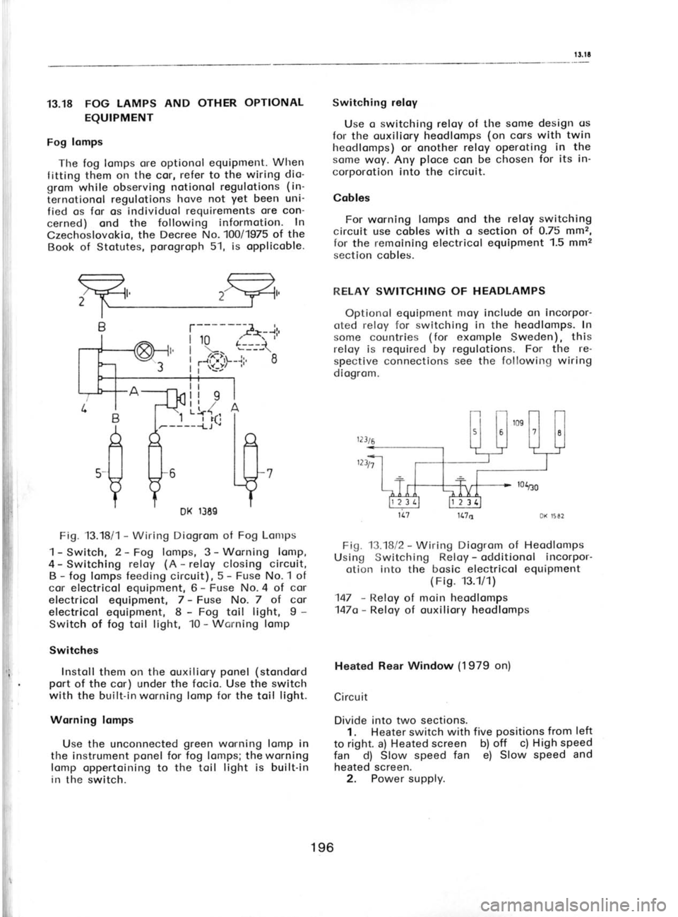
13.18 FOG
LAMPS AND
OTHER OPTIONAL
EQUIPMENT
Fog lomps
The fog lomps ore optionol equipment. When
f itting them on the cor, refer to the wiring dio-
grom while observing notionol regulotions (in-
ternotionol regulotions
hove not yet
been uni-
fied os for os individuol requirements ore
con-
cerned) ond the following informotion. In
Czechoslovokio, the Decree
No.100/1975 of the
Book of Stotutes, porogroph
51, is opplicoble. Switching
reloy
Use o switching reloy of the some design
os
for the ouxiliory heodlomps (on
cors with twin
heodlomps) or onother reloy operoting in the
some woy. Any ploce
con be chosen for its
in-
corporotion into the circuit.
Cobles For worning lomps ond the reloy
switching
circuit use cobles with o section of 0.75 mm2,
for the remoining electricol equipment 1.5 mm2
section cobles.
R,ELAY SWITCHING OF HEADLAMPS
Optionol equipment moy include on incorpor-
crted reloy for switching in the heodlomps. In
some countries (for
exomple Sweden), this
reloy is required by regulotions. For the re-
spective connections see the following wiring
diogrom.
1L7 1L7a DK 1582
Fig. 13.1812 -
Wiring Diogrom of Heodlomps
Using Switching Reloy -
odditionol incorpor-
otion into the bosic electricol equipment
( Fi9. 13.1/1)
147 -
Reloy of moin heodlomps
147o- Reloy of ouxiliory heodlomps
Heated Rear Window (1979
on)
Circuit Divide into two sections.
1. Heater switch with five positions from
left
to right. a) Heated screen b) off c) High speed
fan d) Slow speed fan e) Slow speed and
heated screen. 2. Power supply.
;;---A.i'
t..[9-+'--'o
B
A
ll
Y
5-
r369
Fig. 13.18i 1 -
Wiring Diogrom of Fog Lontps
1- Switch, 2-Fog lomps, 3- Worning lomp,
4 -
Switching reloy (A -
reloy closing circuit,
B -
fog lomps feeding circuit), 5 -
Fuse No.1 of
cor electricol equipment, 6 -
Fuse No. 4 of cor
electricol equipment, 7 -
Fuse No. 7 of cor
electricol equipment, 8 -
Fog toil light, I -
Switch of fog toil light, 10 -
Wcrning lomp
Switches Instoll them on the ouxiliory ponel
(stondord
port of the
cor) under the focio. Use
the switch
with the built-in worning lomp for the toil light.
Worning lomps Use the unconnected green
wo,rning lomp in
the instrument ponel
for fog lomps; the worning
lomp oppertoining to the toil light
is built-in
in the switch.
I
I
I
l';
196
Page 195 of 238
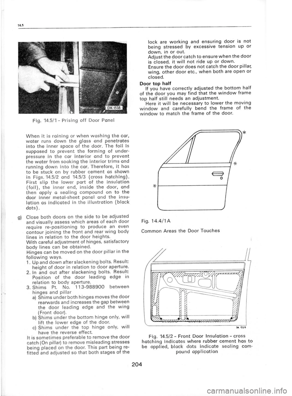
Fig.
M511-
Prising off Door Ponel
When it is roining or when woshing the cor,
woter runs down the gloss
ond penetrotes
into the inner spoce of the door. The
foil is
supposed to prevent
the forming of under-
pressure in the cor interior ond to prevent
the woter from sooking the interior trims ond
running down into the cor. Therefore,
it hos
to be stuck on by rubber cement os shown
in Figs. 14.512 ond 14.5/3 (cross hotching).
First slip the lower port
of the insulotion
(foil), the inner end, inside the door, ond
then opply o seoling compound on to
the
door inner metol-sheet ponel
ond the insu-
lotion os indicoted in the illustrotion (block
dots ) .
Close both doors
on the side to be adjusted
and visually assess which areas of each door
require re-positioning to produce
an even
contour joining
the front and rear
wing body
lines in relation to the door
heights.
With careful adjustment of hinges, satisfactory
body lines
can be obtained.
Hinges can
be moved on the door pillar in
the
following ways.
1 . Up and down after slackening bolts.
Result:
height of door in relation to door ap_erture.
2. In and out after slackening bolts. Result:
Position of
the door leading edge in
relation to bodY aPerture'
3. Shims Pt.
No. 1 13-98B9OO between
hinges and pillar
a) Shims under
both hrnges moves
the door
rearwards and
increases the gap
between
the door leading
edge and the
wing
(Front door).
b) Shims under the bottom hinge
only, will
lift the lower edge
of the door.
c) Shims under the top
hinge only, will
have the reverse effect.
It is
sometimes preferable to remove
the door
catch (On pillar)
to remove misleading stresses
being placed
on the door. This part
being re-
fitted and adjusted so
that both stages of
the lock are
working and
ensuring door is not
being stressed by
excessive tension
up or
down, in or out.
Adjust the door
catch to ensure when
the door
is closed, it will
not ride up or down'
Ensure the door does not catch the door pillar,
wing, other door etc., when both are open or
closed.
Door top half
lf you-have correctly
adjusted the
bottom half
of thb door you
may find that the window frame
top half still needs an adjustment.
Here it will be necessary to
lower the moving
window and carefully bend the
frame of the
window to match the frame
of the door'
Fig. 14.4/14
Common Areas
the Door Touches
Fig. 14.512- Front
Door lnsulotion -
":t;
hotching indicotes where
rubber cement hos to
be opplied, block dots indicote seoling
com'
pound opplicotion
204
Page 199 of 238
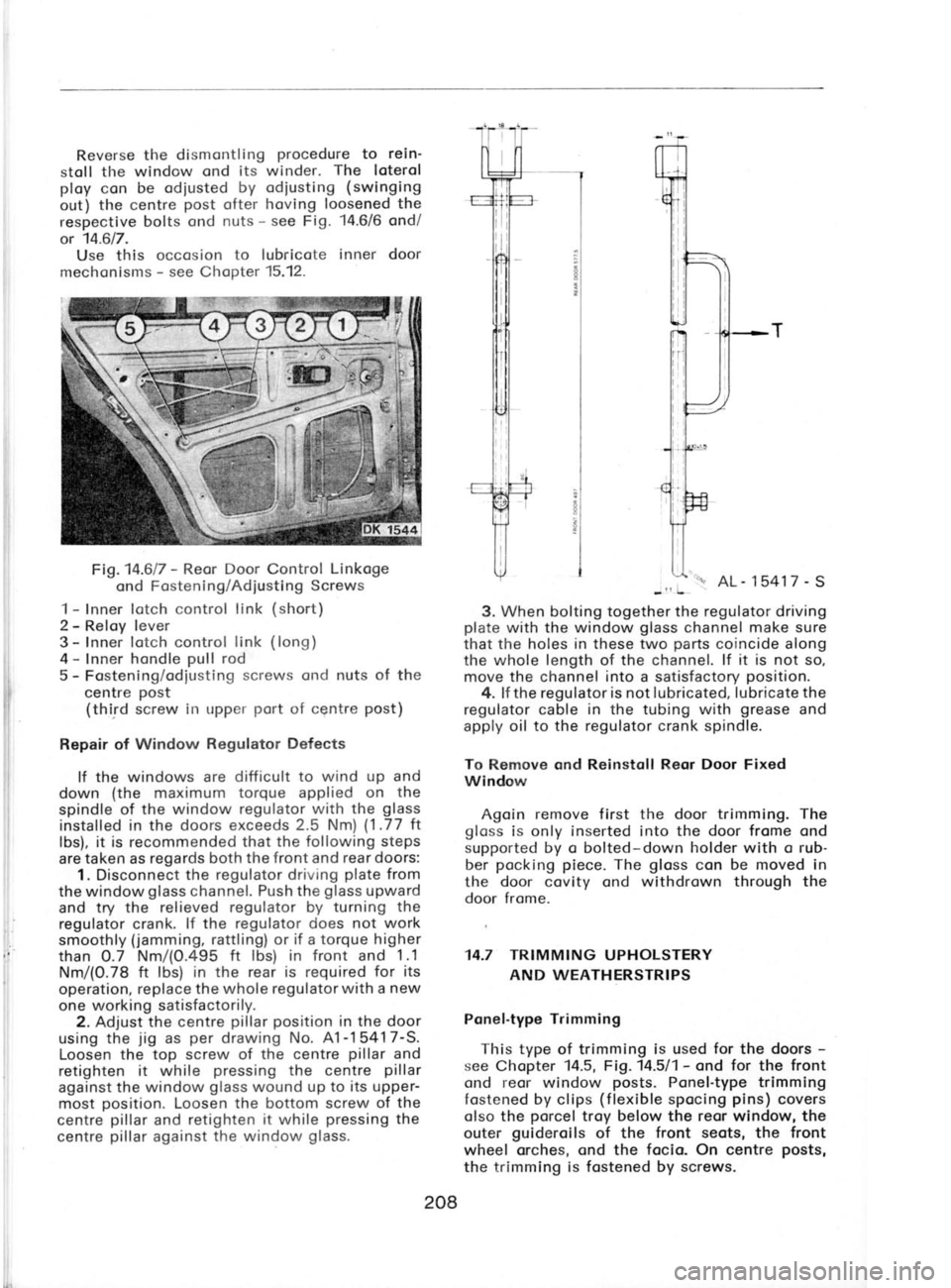
Reverse
the
dismontling procedure
to rein'
stoll tl-re window ond its winder. The
loterol
ploy con be odiusted by odiusting (swinging
out) the centre post
ofter hoving loosened the
respective bolts ond nuts -
see Fig. '14.6/6
ond/
or 14.617.
Use this occosion to lubricote inner door
mechonisms -
see Chopter 15.12.
Fig.14.617 -
Reor Door Control Linkoge
ond Fostening/Adiusting Screws
1 -
Inner lotch control link (short)
2 -
Reloy lever
3 -
lnner lotch control link
(long)
4 -
Inner hondle pull
rod
5 -
Fostening/odiusting screws ond nuts
of
the
centre post
(third screw in upper port
of centre post)
Repair of Window Regulator Defects
lf the windows are difficult to wind up and
down (the
maximum torque applied on the
spindle of the window regulator with the glass
installed in the doors exceeds 2.5 Nm) (1.77
tt
lbs), it is recommended that the following steps
are taken as regards both the front
and rear doors:
1. Disconnect the regulator driving plate
from
the window glass
channel. Push the glass
upward
and try the relieved regulator by turning the
regulator crank. lf the regulator does not work
smoothly (jamming,
rattling) or if
a torque higher
than O.7 Nm/(O.495 ft lbs) in front and 1.1
Nm/(0.78 ft lbs) in the rear is required for its
operation, replace the whole regulator with a new
one working satisfactorily.
2. Adjust the centre pillar position
in the door
using the jig
as per
drawing No. A1-1 5417-S.
Loosen the top screw of the centre pillar
and
retighten it while pressing
the centre pillar
against the window glass
wound up to its upper-
most position.
Loosen the bottom screw of the
centre pillar
and retighten it while pressing
the
centre pillar
against the
window glass. 5417
-
S
-l! L
3. When bolting together the regulator driving
plate with the window glass
channel make sure
that the holes in these two parts
coincide along
the whole length of the channel. lf it is not so,
move the
channel into a satisfactory position.
4. lf the regulator is
not lubricated, lubricate the
regulator cable in the
tubing with grease
and
apply oil to the regulator
crank spindle.
To Remove ond Reinstoll Reor Door Fixed
Window
Agoin remove first the door trimming. The
gloss is only inserted
into the door frome ond
supported by o bolted-down holder with o rub-
ber pocking piece.
The gloss
con be moved in
the door
covity ond withdrown through the
door frome.
14.7 TRIMMING UPHOLSTERY AND WEATHERSTRIPS
Ponel-type Trimming
This type of trimming is used for
the doors -
see Chopter 14.5, Fig.14.511- ond for
the front
ond reor window posts.
Ponel-type trimming
fostened by clips (flexible
spocing pins)
covers
olso the porcel
troy below the reor window, the
outer guideroils
of the front seots, the front
wheel orches, ond the focia. On centre posts,
the trimming is fostened by screws.
208
Page 201 of 238
I
x
li
I
I
.t
the
ploces
from which you
hove removed the
sticking dirt ogoin, ond wipe
the entire body-
work diy, including chromium'ploted ports,
with
chomois leother. Wosh ond
wlpe dry the vor'
nished surfoces with uniform strokes in one
direction, i. e.
not
by circulor movements.
After hoving wiped oll vornished ports
of the
bodywork dry, polish
them with o soft (flonnel)
duster. Do not use polish
of ony kind.
lf the bodywork is so dirty thot it connot be
woshed cleon with woter, use cor
shompoo.
lf it is necessory to refreshen the gloss
of the
finish, use o cor polish
occording to instructions
of its monufocturer. To wosh the underbody,
use o hose ond
running woter, worm or cold; never use petrol,
kerosene, diesel oil, etc.
Remove greose
spots with o cloth, dry or
sooked in petrol
if necessory. To
remove tor, dip
the cloth in kerosene or o speciol
tor removing
preporotion, ond rub the spots. Then
immediotely
wosh owoy oll troces of
kerosene or the tor
removing solution, ond repolish the spots with
o cor polish.
TOUCHING.UP VARNISH
Preporotion:
Removol of Polishes etc.
When touching up o repoired bodywork (dom-
oged surfoce
finish), it is
importont to olso
cleon the surrounding vornish
to prevent
the
touching-up point
from floking off loter on in
ploces of overlopping.
Remove cor polishes
with o shompoo. Silicone
oil, contoined in some bronds
of polishes
ond
preventing the odhesion of the touching-up
point, con be woshed owoy only with o speciol
preporotion. !n Czechoslovokio, this is
for
exomple VENEDIN. Rub with this preporotion
olso vornished oreos which will be roughened
by grinding
where the bore ploces
poss
into
ground ond cemented oreos.
Removol of Rust
Remove rust mechonicolly by grinding
or
rubbing with emery poper
ond woshing with
c derusting ogent (for
exomple SK 2,
which is
bosicolly o 300/s phosphoric
ocid).
Procedure: f irst cleon the rusty spot with
emery poper
No.80 ond 100
or using o grinder.
Then rub the spot with o 15 0/6
solution of
phosphoric ocid (SK 2 deruSter)
heoted up to
40oC. When using o cold solution,
its concen-
trotion must be obout 300/e (undiluted
SK 2
deruster). Work in rubber gloves.
After hoving removed the rust, wosh
the spot
twice. First
with tepid or cold woter,
soft or softened
by odding 2
to 2.501s of sodo,
then
with o solution of chromium trioxide (1 gr.
to
1 litre of soft
woter) heoted
up
to 80oC (thls
is
the so-colled possivoting
rinse). Now let the
spot dry.
Degreosing Degreose the spot to be touched up by rub-
bing it down with trichloroethylene or technicol
petrol.
1. Touching-up with low-boking points -
the most perfect procedure
o) Cleon the touched-up spot, derust
ond
degreose it (see
the previous
porogrophs
on
preporotion)
b) Sproy over with priming point
c) Let the priming point
dry ot 80oC to 110oC
for o period
of 50
or 15 minutes (50 minutes
ot 85oC, 15
minutes ot 110oC)
d) Coot over with synthetic cement or poly-
ester cement
e) Let the cement dry ot 85oC or 110oC for
o period
of 50 or 15 minutes respectively;
when using polyester
cement, the drying
period con be shortened -
this cement dries
of normol temperoture
f ) Grind under
woter with emery poper
No.280
to320till the spot is perfectly
flot ond even,
ond let it dry
g) Sproy with top-coot vornish
h) Let it dry ot 80oC to 110oC for
o period
of
15 or 50 minutes respectively; ofter boking,
the vornish hos
o high gloss
ond it is not
necessory to polish
it
i) Use o polish
to remove
ony visible troces of
tronsition between the originol ond the
new
vornish.
2. Touching-up with
nitro-combinotion vornish
o) Cleon, grind,
derust, ond degreose the spot
to be touched up
b) Apply priming
point with o brush or o
sproy-gun
c) Level up, if
necessory, with on oil-bose
cement (once
or twice)
d) Let
it dry lor 24 hours ond then grind
with
emery poper
No.220
e) Sproy
the entire touched-up oreo with
sproying cement ond let it dry for 24 hours
f) Grind with
emery poper
No. 280 ond 320
under woter till the oreo is perfectly
smooth
ond flot, ond let it dry
g) Sproy the touched-up spot with o vornish
prepored by mixing low-boking
,vornish
(Toolol ond touching-up vornish (300/e);
use
exclusively o
nitro-thinner for diluting the
vornish
210
Page 209 of 238
li
6rz
Ilpuns ''c1e 'se6ulq
-ar puo sa6ugq p1g surs!uDqceu
JooP'srxsluoqseu asoel
loog puD
leuuoq eu16u3
o sseulcDlu! ro, ueql
lcedsul puo
suolsld
reput;Ac leeqM luoil
lo sloog
lsnp uDalc
suld elxo
luoJl alDc!rqnl
uosDes ,9lu!tvl eql leUD puD
ejoleg
esoe.r6 qssr,
rll!r't s6ug:oaq
laoqM 1uo.r;
lcod
6u gsnoq
e^lrp lDull/xoq:oe6 oql
u!
11o a6uoqc
sroart ee.rql poqo
ri1ly
xoq 6u1.raals aql ul
llo dn dot -
a6o:ana;
radlrrt ueoJcspu!M eql
lo tulo! aqt elDolrqnl
smeA orvrl Arana
lnoqy 'V
;r asoalD
ql1rur
laaqM luorl I:osseceu
s6uuoeq aql >1coda.r 's6u1:oeq
;o 6u;1cod asoe:6 eql
lceqc -
11o au16ua eql a6uoqc -
roeA Araae
lnoqv 't
Ja!JJD3
leoqm e:ods
eq1 puo 's1co1
puo sa6ulq
lsuuoq au16ua
puo 'p!l
looq 'roop
eloolrqnl
rolnqlrls!p eql elDclrqnl -"
uJsruDqceu rolDJeleccD eql elDslJqnl *
Arosssceu
Je^eueqrn ro qluour xls ,trena
lnoqv 'z
Arossecau
1g dn do1
puo
le^ol a1lgo.r1ca1e
lcaqC --
rlluoru Arena poqy 'L
:pell3^DJ] saJleruol!l lo Jaqunu
eql uo 6ulpuedep ecuDuelutotu 6ul1uaua1duoc
'cr3 slvnusrNl
3l^ilr NO oNtCN3d3(l S80f scNVN3rNlVl l
'rnrroleq pe1l1oads sD slD^Jelu! eu!l uo
6u;puadap
sqo! 6ugclnJas rlllM peluauelddns 'renoeJou
'eJD
)oog reqcnon eql
ul pelsll
sqo! ecuoualulDhl
'6u1cgn.ras
rol Joc s1q s6u;.rq eq qclqrrrr
ol uollols ec!^res
eql u!
e:n1ou61s lol
loo8 Jeqcnon
s!q1 sluasald
Jesn Jo JauMo JDc eql 'slusujnsop
JDc Jeqlo
aql qllM
JDc eql
lo :aAnq aql
ol Je^o papuDq
loog Jeqcnon ec!^res
eql u! lllonp;n1pul
Pe!]
-qceds ero'sqo! ecuDualulotu lDnP!^!Pul eqt
cf]lfnvul s3u+ll loll) Jo u38wnN
3HI NO SCNSON]dSO Nl :ICNVN:lrNlVhl
.tL.9L or qDnorql
g'91. s.raldoqC ol JeleJ sluauoduoc JDc
lonp!^lPul
aql 6ugu.lacuoc suollonJlsu! ecuDuelulout JoJ'9
'9
.il
:.1
.,1
adAl gue6relap
CH -
TtO JNleNf
.uep! loraus6 o Aq
ro
A;lcal!p reqlle palDc!pu!
sr
spuDJq po
oql
,o auros
lo ssDlc
lllsocsgr aq1
's:acnpo.rd llo Aq
papueuluocer
it11o;ceds .to
rernlcolnuour roc eql lq palsel's:ecnpord pllorln
uMoul lleM lo sl!o elqollns
lo spuDJq
lDre^es
. .,{}!m uo!}DrrJo}u! Jno
lueua;ddns 07171 'ecue
*'T*.+ueAoJd Je^elDLlM lo llo lce:Joc eql esooqc
ol
a1q;ssod sl l! 'puorq
l!o aql
puD
uollocll!ssDlc
' s!rll o1 6ugp.roccy '(s.raau;6u3
an;lourolnv lo
' Alalcog uDolreurv) uollDc!t!ssDlc
3VS peno:d
'
-do A;1ouo11ou.relu! ell] eloc!pu! elr 's11o
.ro3
SOln'lJ SClnU:lS UfHrO CNV
slNvcrusnl c30N3l il toc3u
z'91
-les
6u;1ocr-rqn; Z VO1AI eql
olduoxe
ro; 'saraqds
-orxlD 00C lsDel
lD
,o ernssald o Duldole^ep
(su1d 6u!l
lo uorlDc!rqnl
:o;) un6 esoere
's:oa{ oM} ro sar}auol!l 000'09 ral}D
(Sl
OZL
VAO)S q11m)
lcaqc lcue1c11;a
relsooq e)Drg
'Jeuoos pelle^Dr] ueeq
anoq Aeql l! seJleuolll
000'001 .ro s:oeA an1;
ra1;o rualsls
esDeleJ qclnlc puo
uelsAs elDJq
cl1no:plq eql 'o s1.rod .reqqnr
llD ]o a6uoq3
's.roaA eorql ol oMl Jallo
luolooc ;o a6uoq3
's:oaA
aarql ot oMl reUD prnlt
alDrq
1o a6uoq3 -
lueurd;nb3
puD sgor ecuDuelulDlN pepueuuoceu
teqlo
s6nld 6ur1.rods eql
;o
luauecoldeJ lsDl eql uoJl
sAorvrlo pelunoc
aq plnoqs (OOO'02
ol
000'gL ) serlaruoll;
luD^elsJr!
s!
puorq po
| *slugod peloclrqnl
:ssolc 0e ro
ozlM0z fvs
I uDc-l!o raqlo
puD
6ulranoc ''e'!
| '6u1:oeq
esDoleJ
'l11socs1n Lunlpeu lo l!O
I qcln;c'.ro1nq!rls!C
co9 *
ol9z-
l/V\oL 3vs
co0l+ol0L- | ozlMoz
lY.s^ | eu;6u3
cooz+-ol0 | ot 3vs
co9t*ol0L+ | 0t3vs
co09* ol
9L+ | 09
fvs
ernloladual lue!quv 1u1od
6ulloclrqnl
z'9 t-t'9 t s6nld 6u;1rod5
'L
Notrvl tuolNl 'lvu3Nfe
t'91
Page 210 of 238
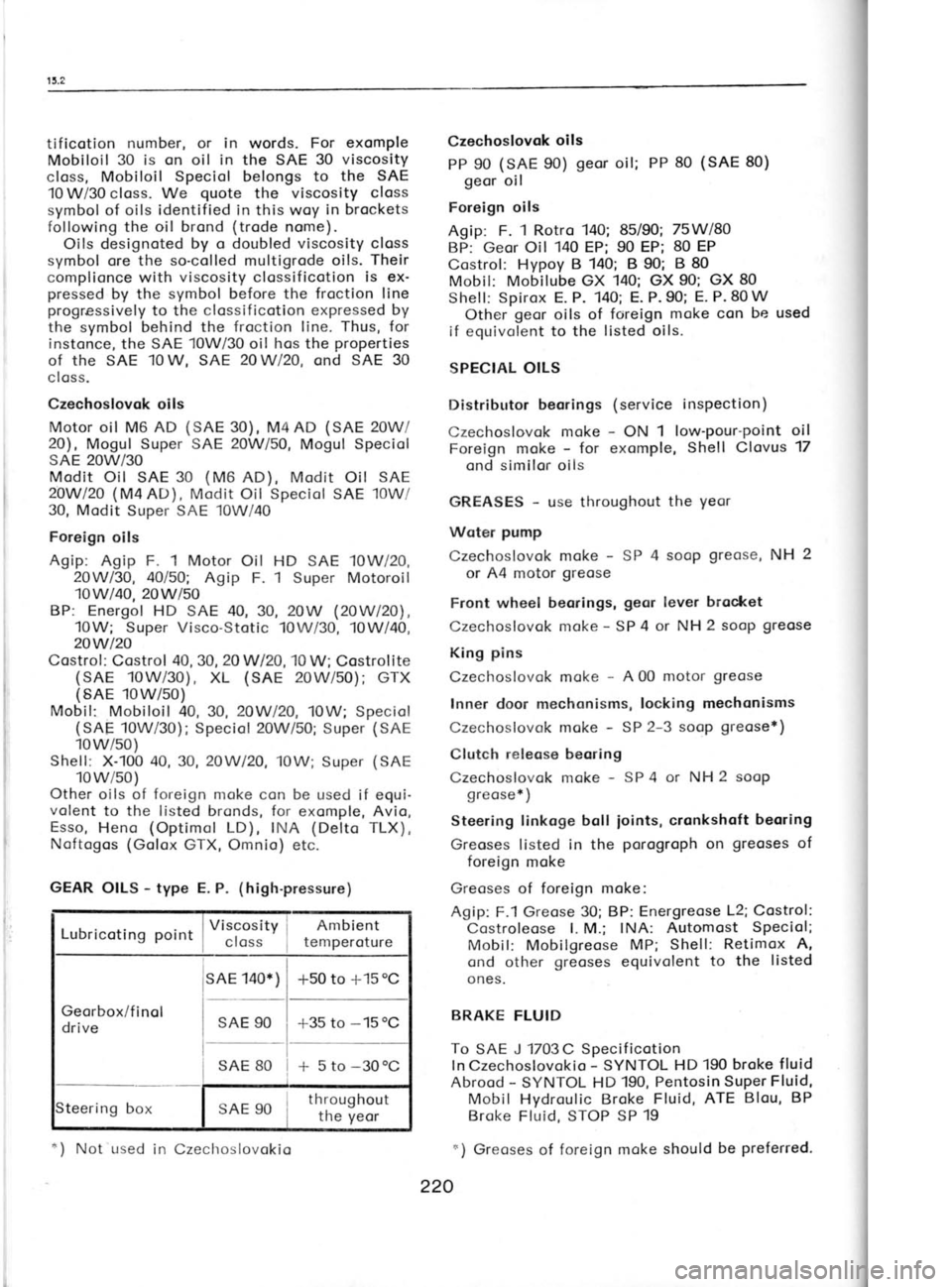
tificotion
number, or in
words. For exomple
Mobiloil 30 is on oil in the SAE 30 viscosity
closs, Mobiloil Speciol belongs to the SAE
10 W/30 closs. We quote
the viscosity closs
symbol of oils identified
in this woy in brockets
following the oil brond (trode
nome).
Oils designoted by o doubled viscosity closs
symbol ore the so-colled multigrode oils. Their
complionce with viscosity clossificotion is ex-
pressed by the symbol before the froction line
progressively to the clossificotion expressed by
the symbol behind the froction line. Thus,
for
instonce, the SAE 10W/30 oil hos the properties
of the sAE 10w, sAE 20w120,
ond sAE 30
closs.
Czechoslovok oils
Motor oil M6 AD (SAE
30), M4AD (SAE
20W/
20), Mogul Super SAE 20W50,
Mogul Speciol
SAE 2OW/30
Modit Oil SAE 30 (M6
AD), Modit Oil SAE
2OWl2O (M4AD), Modit Oil Speciol
SAE 10W/
30, Modit Super SAE 10W/40
Foreign oils
Agip: Agip F. 1 Motor Oil HD SAE 10W/20,
2OWl30, 4Ol5O; Agip F. 1
Super Motoroil
10w/40,20wl50
BP: Energol HD SAE 40, 30, 2OW (2OW|?O),
10W; Super Visco-Stotic 10Wi30, 10W/40,
20wt20
Costrof : Costrol 40,
30, 20Wl2O, '10
W; Costrolite
(SAE 10W/30), XL (SAE 20W/50);
GTX
(SAE 10w/50)
Mobil: Mobiloil 40, 30, 2OWl2O,
10W; Speciol
(SAE 10W/30); Speciol 20W/50; Super (SAE
10w/so)
Shef l; X-100 40, 30, 2OWl20,
10W; Super (SAE
10w/so)
Other oils of foreign moke con be used if equi-
volent to the listed bronds, for
exomple, Avio,
Esso, Heno (Optimol
LD), INA (Delto TLX),
Noftogos (Golox GTX, Omnio) etc.
GEAR OILS -
type E. P. (high-pressure)
I Viscosity j Ambient
Lubricoting noint
I closs
! temperoture
sAE 140*) -r50
to +15 oC
Georbox/f inol
drive SAE
90
*35 to -15
oC
* 5 to -30oC
SAE 80
teering box SAE 90 throughout
the yeor Czechoslovok
oils
PP 90 (SAE
90) geor
oil; PP 80 (SAE 80)
geor oil
Foreign oils
Agip: F. 1 Rotro 140; 85/90; 75Wl8O
BP: Geor Oil 140
EP; 90 EP; 80 EP
Costrol: Hypoy B 140; B 90; B 80
Mobil: Mobilube GX 140; GX 90; GX 80
Shell: Spirox E. P. 140; E. P. 90; E. P. 80 W
Other geor
oils of foreign moke con be used
if equivolent to the listed oils.
SPECIAL OILS
Distributor beorings (service inspection)
Czechoslovok moke -
ON 1 low'pour-point oil
Foreign moke -
for exomple, Shell Clovus 17
ond similor oils
GREASES -
use throughout the yeor
Woter pump
Czechoslovok moke -
SP 4 sooP greose,
NH 2
or A4 motor greose
Front wheel beorings, geor lever
brocket
Czechoslovok moke -
SP 4 or NH 2 soop greose
King pins
Czechoslovok moke -
A 00 motor greose
Inner door mechonisms, locking mechonisms
Czechoslovok moke -
SP 2-3 soop greose*)
Clutch releose beoring
Czechoslovok moke -
SP 4 or NH 2 soop
greose* )
Steering tinkoge boll
ioints, cronkshoft
beoring
Greoses listed in the porogroph
on greoses
of
foreign moke
Greoses of foreign moke:
Agip: F.1 Greose 30; BP: Energreose L2; Costrol:
Costroleose l. M.; INA: Automost Speciol;
Mobil: Mobilgreose MP;
Shell: Retimox A,
ond other greoses
equivolent to
the listed
ones.
BRAKE FLUID
To SAE J 1703C Specificotion
ln Czechoslovokio -
SYNTOL HD 190 broke fluid
Abrood -
SYNTOL HD 190, Pentosin
Super Fluid,
Mobil Hydroulic Broke Fluid, ATE Blou, BP
Broke Fluid, STOP SP 19
r) Greoses of foreign moke should be preferred.
220
*)
Not used
in Czechoslovokio
Page 212 of 238
I-
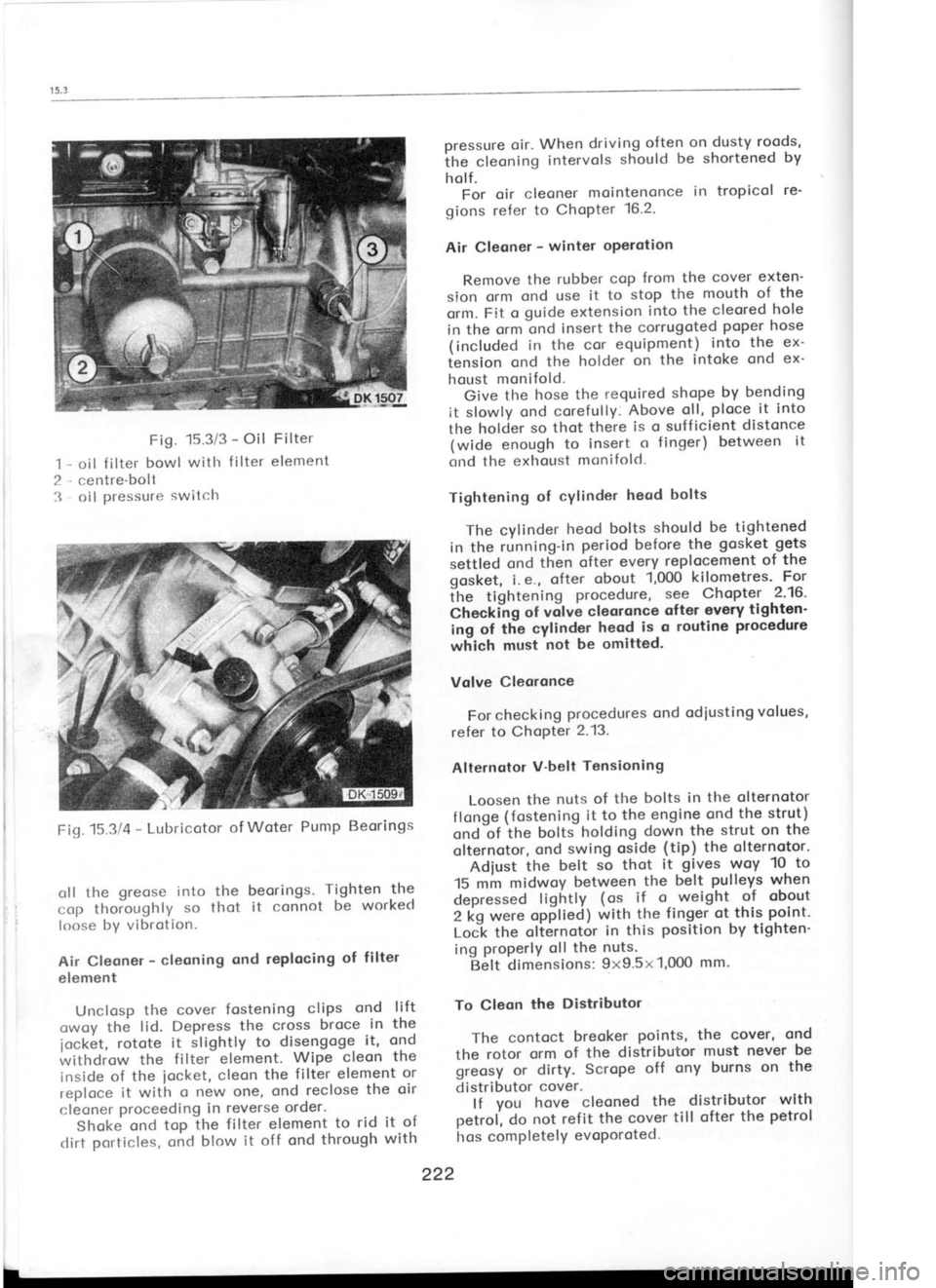
.'t Fig.
15.3/3 -
Oil Filter
oil f ilter bowl
witlr f ilter
element
centre-boll oil pressure
switclr pressure
oir. When driving often
on dusty roods,
ihe cleoning intervols
should
be shortened by
holf. For oir cleoner mointenonce in tropicol
re'
gions refer to
ChoPter 16.2.
Air Cleoner -
winter oPerotion
Remove the rubber
cop from
the cover exten-
sion orm ond
use it to stop the mouth of
the
orm. Fit o guide extension into
the cleored hole
in the ornr ond
insert the
corrugoted poper hose
(included in the
cor equipment) into
the
ex-
iension ond
the holder on the
intoke ond
ex-
houst monifold.
Give the
hose the required shope by
bending
it slowly ond corefully. Above
oll, ploce
it into
the holcier so thot
there is
o suff icient distonce
(wide enough to
insert o
finger) between it
crnd the exhot-tst monifold.
Tightening of
cYlinder heod bolts
The cylinder heod
bolts should be tightened
in the running-in period before
the gosket gets
settled ond then
ofter every replocement of the
gosket, i.e., ofter
obout 1,000
kilometres' For
itre tightening procedure,
s9e
Chopter
-2'16'
Check'ilg of vilve
cleoronce ofter
every tighten'
ing of tlie
cylinder heod
is o
routine procedure
which must not be omitted.
Volve Cleoronce
For checking procedures
ond odiusting volues,
refer to ChoPter 2.13.
Alternotor V'belt
Tensioning
Loosen the
nuts of the bolts
in the olternotor
f longe (fostening
it to
the engine ond
the strut)
ond'of itre
bottJ holding down
the strut on
the
olternotor, ond
swing
oside (tip)
the olternotor'
Adiust the
belt so
thot it gives
woy 10- to
15 mm midwoy between the
belt pulleys
when
depressed lightly (ot
if o- weight of obout
2 kg were opplieal with
the
finger ot this point'
LoCk the
olternotor in
this position
by tighten-
ing properlY
oll the nuts.
Belt dimensions: 9x9.5x1,0O0 mm.
To Cleon the
Distributor
The contoct breoker points, the
cover, ond
the rotor orm
of the distributor must never
be
greosy or dirty. Scrope off
ony burns on the
distributor cover.
lf you hove
cleoned the
distributor with
oetrol, do
not ref it the cover till ofter
the petrol
hos comPletelY evoPoroted.
222
oll
the greose
into the beorings. Tighten
the
cop thoioughly so
thot it connot be worked
loose by vibrotion.
Air Cleoner -
cleoning ond
replocing of
filter
element
Unclosp the cover
fostening clips
and lift
owoy the lid. Depress the
cross broce in
the
1ock6t, rotote
it
slightly to disengoge it, ond
withdrow the filter
element. Wipe
cleon the
inside of the
iocket, cleon
the filter
element or
reploce it with o new
one, ond reclose the oir
cleoner proceeding
in reverse order.
Shoke ond
top the filtet element to
rid it of
clirt porticles, oncl
blow it off ond through with
Fiq.15314
-
Lubricotor of
Woter Pump Beorings
Page 214 of 238

Fig.
15.3/8 -
Distributor Adiusting Elements
1 -
contoct holder, 2 -
rotor orm, 3- com,
4 -
distributor brocket, 5 -
distributor brocket
clomping bolt
Alwoys turn the engine clockwise to eliminote ony ploy
in the distributor drive geor
ond to
ovoid loosening of the bolt. To relieve the
com-
pression resistonce, it
is recommended to bock
off the sporking plugs.
b) Stroboscopic method:
When using this method, the volues of the
bosic ignition timing ond
the odvonce con-
trolled by the centrifugol timing control (for
its
diogrom refer to Chopter 13.5) should be odded
upwhile multiplying bytwo
the odded upvolues
occording to the diogrom. Any effect of the
vocuum control must be
eliminoted by discorr-
necting the respective hose (connecting
the
distributor vocuum unit with the corburettor).
The meosuring procedure
is indicoted by the
diognostic equipment itself.
To Adiust ldling Speed
Use the oir-correction screw (speed
cor-
rection screw). The speed decreoses when ro-
toting the screw clockwise ond increoses when
rototing it onticlockwise.
Adiust the idling speed in occordonce with
the tochometer ond within the limits specified
in the following porogroph "To
Adiust ldle
Run". The engine must be wormed-up
before
storting the odjusting procedure (see
olso the
following porogrophs) ond its ignition must be
in perfect
condition (distributor
contoct-breoker
points, sporking plug
electrodes, ond ignition
odvonce).
N o t e : For the bosic position
of the odiusting
screw refer to Chopter 2.19 - "Mointenonce
ond
Adiusting". Fig.
15.3/9 -
Air-correction Screw -
idling speed
correction screw
To Adiust ldle
Run
Acljust the contoct-breoker point
gop,
the gop
of the sporking plug
electrodes, ond
the ig-
nition odvonce. Then check
the
volve cleoronce
(if there is no cleoronce, odiust
the
volves),
cleon the oir intoke filter
element, ond moke
sure thot the occelerotor pedol link hos
the re'
quired free trovel -
see Chopter 12.2-
Use o needle to remove the plug
covering
the fost-idling screw
ond let the engine run ot
obout 2,000 r. p.
m. to ottoin on oil temperoture
of 70oC. Insert the probe
of the thermonreter
into the hole for the oil diPstick'
Now connect the
speed indicotor (tocho-
meter) ond the onolyzer of
corbon
.monoxide
(contoined in exhoust fumes). Use
the oir'cor-
iection screw (Fig.
15.3/9) to set the
speed
-r-?n
at 800 l;; t.
p. ni. cnd the fost-idling screw
(Fiq. 15.3/10) to odiust the
content of corbon
moioxide to 2*0.50/s or the oir-fuel proportion-
by-weight mixing rotio,
comporoble with
the
specif ied corbon monoxide content, to
1+.2 +$.t.
After about one minute of
the continued idle
running recheck the odiustment ond
correct it,
if necelsory. Close the hole
with the
fost-idling
screw by driving in o
new plug with
its bottom
outword.
Note: For the bosic position of
odiusting
screws refer to Chopter 2.19 - "Mointenonce
ond Adjustment".
To Lubricote Accelerotor Mechonism
Pour severol drops of oil into
the end of the
bowden coble tubing ond lubricote both
ioints
(on top ond below)- of the corburettor pull-rod
itself with obout one drop of oil. Then
depress
224