1980 CHEVROLET CITATION fuel
[x] Cancel search: fuelPage 63 of 95
Downloaded from www.Manualslib.com manuals search engine CATALYTIC CONVERTER
. The catalytic converter is an emission control device added to the
exhaust system to reduce exhaust gas pollutants. The converter
contains a ceramic material coated with noble metal catalysts. To prevent
contamination of the cata lysts,
unle~ded gasoline must be used. Unleaded gasoline
also reduc es combustion chamber deposits and exhaust system corrosion.
The catalytic converter requires the use of unleaded gasoline. Use
of leaded gasoline will cause the converter to lose its effectiveness for emission control. On some engines, the catalyst must be changed at cer tain inter vals in orde r for
the emissio n control system to continue to operat e properly. The change intervals
are speci fied in Section C of the Maintenance Schedule folder.
On cars that require this catalyst change, the word "EMISSION" will
appear on an indicator in the speedometer face at the specified change
in terval
s. This is a reminder that the cata lyst must be changed. (If the indicator does not appear, your car does not need this catalyst change).
Your Chevrolet deale r will perform the lirst cataly st cha nge at no charge, whether yO'u are the first owner or a subsequent owner. As part of this service, the indicator
should be reset to appear
at the next specified chang e interval. To help prevent
damage:
1. Keep your engine properly maintained. Engine malfunctions involving th e electrical, carburetion or ignition systems may result in unusually high
conve rter and exhaust system temperatures .
Do not keep driving your vehicle if you detect engine misfire. noticeable loss of
perform,8nce. or other unusual operating conditions. Instead, have it serviced promptly. A properly ···maintained engine will he lp avoid
malfunction s that could damage the converter.
It will also help provide good
emissio.n cq!).,trol and gasoline economy. See the Maintenance Schedule folder
for inform ation on inspecting a
nd maintaining the engi ne. exhaust system.
and other compone nts.
2 .
Do not drive through, idle, or park your vehicle over combustibl e materials,
s u ch as grass
or leaves. They could 'touch the hot exhaust system and ignite.
3. Do n o t push or tow this vehicle 10 stan it. This cou ld damage (he converter.
Disregarding this information could damage the catalytic converter, the vehicle,
or nearby property.
C-4 (COMPUTER CONTROLLED CATALYTIC CONVERTER)
SYSTEM If your new car was purchased in California, it has a special emission control
system, called
the C-4 (Computer Co ntrolled Catalytic Converter) System. The C4 System monitors the exhaust stream with an oxygen sensor. Based 4
on senso r signals, the electr onic control module adjusts the carburetor
air~fuel ratio as needed. It is very important to use only unleaded gasoline
in cars with
the C-4 System. Leaded gasoline will damage the oxygen
sensor. which may affect emission
control, fuel economy and drivability.
Some cars equipped with the C-4 System need an oxygen sensOr change
at the intervals specified in Section C of the Maintenance Schedule folder.
On these cars, an oxyge n sensor maintenance reminder is included in the
instrument paneL The word "EMISSIONS" is designed to appear in a
window in the speedometer face at the intervals outlined in the Maintenance
Schedule folder. The "EMISSIONS " indicator is a reminder that the oxygen
sensor must be repl aced with a new sensor.
Such replacement is necessary
in order to maintain the correct operation of the emiss ion control system.
The indicator must be reset as part of this service.
5-2
Page 64 of 95
Downloaded from www.Manualslib.com manuals search engine On all C-4 cars, a "CHECK ENGINE" light on the instrument panel is
designed to come on during engine starting , to let you know the bulb is working. (The light will stay on a short time after the engine starts.) If the light comes on while driving, service to the emission control system
may be required. See your Chevrolet dealer' as soon as possible for an inspection of the system. Continued driving without having the C-4 System serviced _ could eventually
cause damage
to the emission control system . It could also affect fuel
e conomy and drivabili -ty.
ENGINE OIL AND FILTER RECOMMENDATIONS • Engine oils' are labeled on 'the containers with various API (American
Petroleum Institute) designations 6f quality. Use engine oils that are labeled
5E or SE/CC. Do not use oils labeled only SA, 5B, 5C, SD, CA, CB, CC or CD; _or oils with the combination label SE and CD (SE/CD). Higher
quality oils labeled SF will be introduced soon (late 1979, or 1980). These SF oils are preferred and should be used when available.
• The oil and filter change intervals for your engine are based on the use of SE-quality or SF-quality oils and ,high- quality filters such as AC oil filters. Using oils other than SE-quality or SF-quality oils, or oil change intervals
longer than recommended. could reduce -engine life and might affect your
warranty.
• Your engine was filled with a high·quality engine oil when it was built. You do ,not have to change this oil before the suggested change period.
•
If your normal driving does nQt include one or more of the four "severe service" conditions listed below. change the oil every 7,500 miles (12 000 ' kilometers) or 12 months, whichever comes first. Change the oillilter at the
first oil change. then every second oil change, if mileage (7,500 miles or 12
000. kilom~ters) determines .w ,hen you change the oil. If _time (12 months)
determines when you change the oil, change the filter with every oil change.
• Change the oil and oil filter every 3,000 miles (4 800 kilometers) , or three
months if you often drive under one or more of these 'severe service·,~.
conditions: • Driving in dusty areas
• Towing ,3 trailer
• Frequent idling or idling for long periods
• Driving 4 miles (6 kilometers) br'less in freezing weather,o~other short trips in cold weather, where the engine does not thoTough ,ly warm up.
• Change the oil and oil filter as soon as -possible after driving in a dust
storm.
Oil Viscosity
Engine oil viscosity (thickness) has an effect on fuel economy. Lowec viscosity
engine oils can provide increased , fuel " economy; however, higher temperature
weather conditions require higher viscosity engine oils for satisf~ctory lubrication.
To. get the best fuel economy with your-1980 Chevrolet, -iou should use -,, ' .
fuel. 'saviiJ.&:_engine oil ohhe_ proper viscosity. These oils call_ be found. in serviCe
stations and other retail stores. They are-identified by words such as: "Energy Saving," "Conserves Gasoline," "Gas Saving," "Gasoline Saving," '''Friction
Reducing," "Improved Gasoline Mileage" or "Fuel Saving."
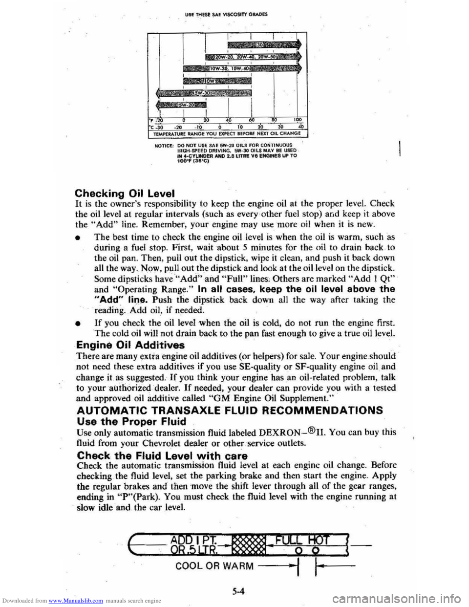
The following chart lists the engine ' oil viscosities recommended for the
temperature range you expect before the next oil change. For lemperalures above ,_18°C (O"F),SAE lOW-30 is -the preferred viscosity grade. Ircold-weather starting
problems
are encountered at temperatures below -lSoC (
5-3
Page 65 of 95
Downloaded from www.Manualslib.com manuals search engine USE Tlltst: SAE VISCOSITY GItotoDH
I , , , cl.
*
::0';'~ ,.,..~,: , , , ,
I
lOW , , , ,
,
I I I I , . , " • '" ,~, ." ., , " " " ~ lVitPl .... 1Ul:( lAN<* YOU ElU'EClltfOll( NUT OIl CHANG(
NOTICE: 00 NOT USE SA~ 5W-2 0 OilS fOA CONTINUOUS HIGH-SPEEQ OAIVING. 1,iW-30 OILS MAY III USED .. 4.CYIJNO!!R AND 2.lIll1AE VII EItClMES UP TO 104)
the oil level at regular intervals (such as every 'o ther fuel stop) and keep it above
th e "Add" line. Rem ember, your engine may use more oil when it is new .
• The best time to check the engine oil level is when the oil is warm, such as
during a fuel stop. First, wait about 5 minutes for the oil to drain back to
the oil pan, Then, pull out the dipstick, wipe
it clean, and push it back down
all the way . Now , pull out.th e dipstick and look at the oil-level on the dipstick.
Some
dipSlicks have "Add" and "Full" lines , Others are marked "Add! Qt"
and "Operaling Range." In all cases, keep the oil level above the
"Add" line. Push· the dipstick back down all the way after taking the
reading. _ A ·dd oil , if needed.
• If you check the oil level when the oil is cold, do no t run the engine first. The cold oil wilJ not drain back to the pan fast enough to give a true oil level.
Engine Oil Additives
There are many extra engine oil additives (or helpers) for sale. Your engine should
not need these extra additives if you use SE-quality or SF·quality engine oil and
change
it as suggested. If you think your engine has .an oil-related problem, talk
to your authorized dealer.
If needed, your dealer can provide you with a tested
and approved oil additive called "GM Engine Oil Supplement."
AUTOMATIC TRANSAXLE FLUID RECOMMENDATIONS
Use the Proper Fluid Use only automatic transmission fluid labe led DEXRON-®II. You can buy this
fluid from your Chevrolet dealer or
othe~,'service outlets.
Check the Fluid Level with care Check the automatic transmission fluid level at each engine oil change. Before
checking the fluid level, set the parking brake and then start the engine. AppJy
the regular brakes and then
'mov e the shift lever through all of the gear ranges,
ending in
"P '·(Park). You must check the fluid level with the engine funning at
slow idle and the car level.
I-c ..... --=---=..,~ ..... B9"""5IL.u;~~"-·, __ .........,; ..... _·F_%¥-W+--T -l{
COOL OR WARM -j ""I ,~-
5-4
Page 66 of 95
Downloaded from www.Manualslib.com manuals search engine NOTICE: You cannot read the correct fluid level if you have just driven the car for a long time at high speed, in city traffic in hot weather, or if the car has been pulling a trailer. Wait. until the fluid has cooled down (about 30 minutes).
Remove the dipstick located on the driver's side forward of the cowl. Carefully
touch the wet end of the dipstick to find out if the fluid is cool, warm or hot. Wipe
it clean and push it back in until the cap seats. Pull
out the dipstick and read the
fluid level.
• If it felt cool or warm (about room temperature), the level should be
between the dimples above the "Full" mark.
• If it was too hot to hold. the level should be at or in the hatched area.
Add just enough DEXRON-®n fluid to fill the transaxle. It takes only 0.5 liter
(one pint)to raise the level from "Add" to "Full" with a hot transaxle.
Do not overfill the transaxle. Overfilling can cause foaming and loss of fluid, which
could result in transaxle damage.
Automatic Transaxle Drain Intervals
Change the transmission fluid and change the filter (or clean the screen) as
outlined in Section
A of the Maintenance Schedule folder.
ELECTRIC FAN
CAUTION: Keep hands, tools, and clothing away from the angine cooling fan to help prevent personal injury. This fan is electric and can come on whether or not the engine is running. The fan can start automatically in response to a heat sensor when the ignition is in the "Run" position.
ENGINE COOLING SYSTEM
The coolant recovery system is standard. The coolant in the radiator expands with
heat, and the overflow collects in the recovery tank. When the system cools down,
the coolant
is drawn back into the radiator.
The cooling system was filled at the factory with a quality coolant that meets
GM Specification 1899-M. The cooling system is designed to use coolant (a mixture
of water and ethylene glycol antifreeze) rather than plain water. The coolant
solution should be used year round. It has many advantages, such as:
• provides freezing protection down to _37°C, (-34°P)
•
provides boiling protection up to 128QC, (262°P)
•
protects against rust and corrosion in the cooling system,
• maintains the proper engine temperature for efficient operation and emission
control, and
• allows proper operation of the coolant temperature light (or gage).
See Section A of the Maintenance Schedule folder to find out when the coolant
must
be replaced.
COOLING SYSTEM CARE
Check the cooling system at regular intervals, such as during fuel stops. You
usually do not need to remove the radiator cap to check the coolant level. Lift
the engine hood and look at the "see through" coolant recovery tank. When the
engine
is cold, the coolant level -should be at or slightly above the "Full Cold"
mark on the tank. When the engine has fully warmed up, the level should be at ')r slightly below the "Full Hot" mark on the tank. If the coolant level is low,
5-5
Page 72 of 95
Downloaded from www.Manualslib.com manuals search engine LUGGAGE/CARGO LOAO CAPACITY
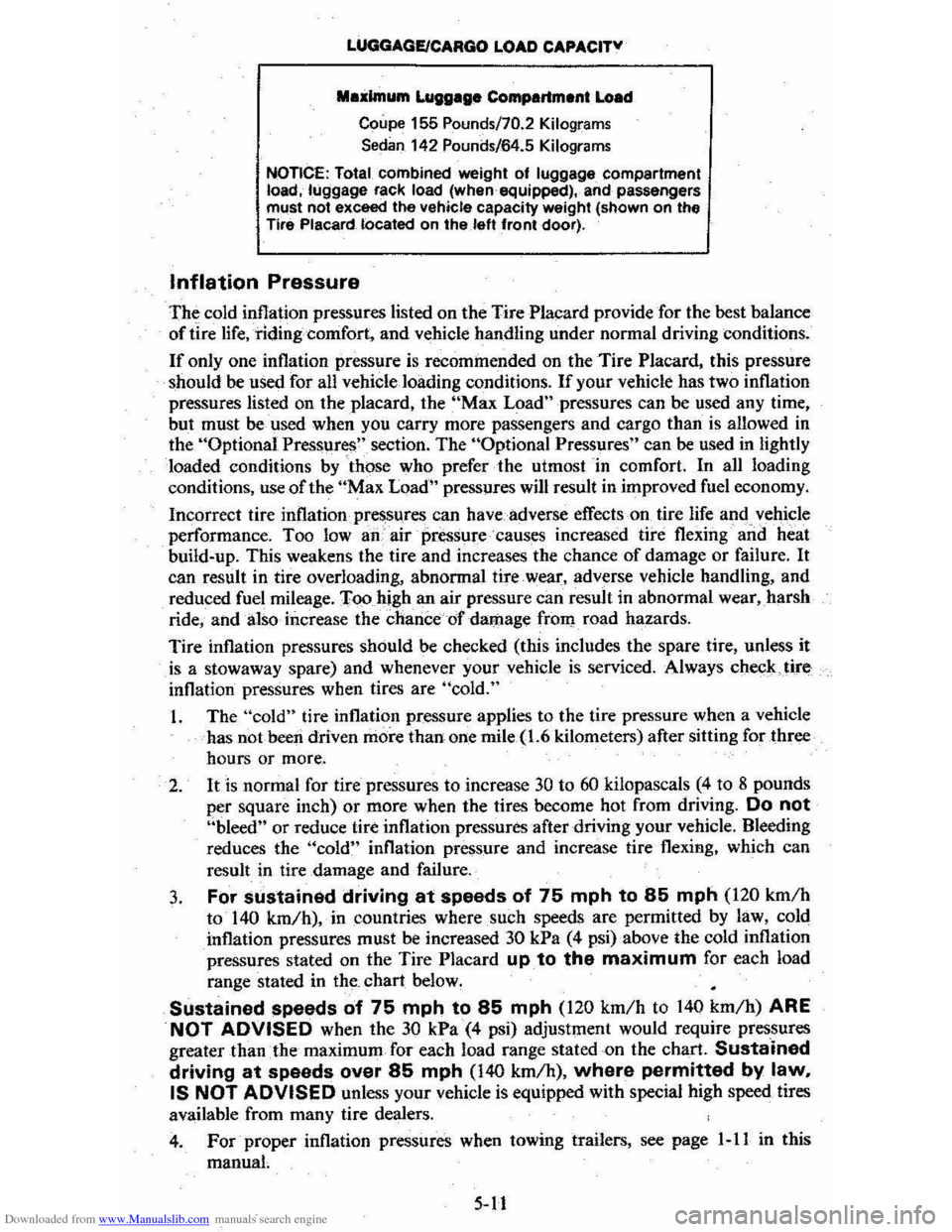
Maximum Luggage Compartment Load
Coupe 155 Pounds/70.2 Kilograms
Sedan 142 Pounds/64.5 Kilograms
NOTICE: Total combined weight of luggage compartment
load, luggage rack load (when-equipped) •. and passengers must not exceed the vehicle capacity weight (shown on the Tire Placard lOcated on the.left front door).
Inflation Pressure
The: cold inflation pressures listed on the Tire Placard provide for the best balance
of tire life, riding comfort. and vehicle handling under normal driving conditions.
If only one inflation pressure is recommended on the Tire Placard, this pressure
should be used for aU vehicle loading conditions. If your vehicle has two inflation
pressures listed on the placard, the "Max LDad" pressures can be used any time,
but must be used when you carry more passengers and cargo than is allowed in
the "Optional Pressures" section. The "Optional Pressures" can be used in lightly
loaded conditions by
'those who prefer the utmost in comfort. In all loading
conditions, use of the "Max Load" pressures will result in improved fuel economy.
Incorrect tire inflation pressures
can have adverse effects on tire life and_vehicle performance. Too Iowan" air pressure·"causes increased tire flexing and heat
build-up. This weakens the tire and increases the chance of damage or failure. It
can result in tire overloading, abnormal tire wear, adverse vehicle handling, and
reduced fuel mileage. 'I'oohigh
an air pressure can result in abnormal wear, harsh
ride, and also increase the chance of dar:nage from road hazards.
Tire inflation pressures should be checked (this includes the spare tire, unless it
is a stowaway spare) and whenever your vehicle is serviced. Always checJ<.,tire
inflation pressures when tires are "cold."
1. The "cold" tire inflation pressure applies to the tire pressure when a vehicle
has
not· been driven more than-one mile (1.6 kilometers) after sitting for three
hours or more.
2. It is normal for tire pressures to increase 30 to 60 kilopascals (4 to 8 pounds
per square inch)
or more when the tires become hot from driving. Do not "bleed" or reduce tire inflation pressures after driving your vehicle. Bleeding
reduces the
"cold" inflation pressure and increase tire flexing, which can
result in tire damage and failure.
3. FOr sustained driving at speeds of 75 mph to 85 mph (120 km/h to 140 km/h),in countries where such speeds are permitted by law, cold
inflation pressures must be increased
30 kPa (4 psi) above the cold inflation
pressures stated on the Tire Placard up to the maximum for each load
range stated in
the_ chart below.
Sustained speeds of 75 mph to 85 mph (120 km/h to 140 km/h) ARE
NOT ADVISED when the 30 kPa (4 psi) adjustment would require pressures greater than the maximum for each load range stated on the chart. Sustained
driving at speeds over 85 mph (140 km/h), where permitted by law. IS NOT ADVISED unless your vehicle is equipped with special high speed tires
available from many tire dealers.
4. Forproper inflation pressures when towing trailers, see page 1-11 in this
manuat
5-11
Page 84 of 95
Downloaded from www.Manualslib.com manuals search engine TIRE INFORMATION
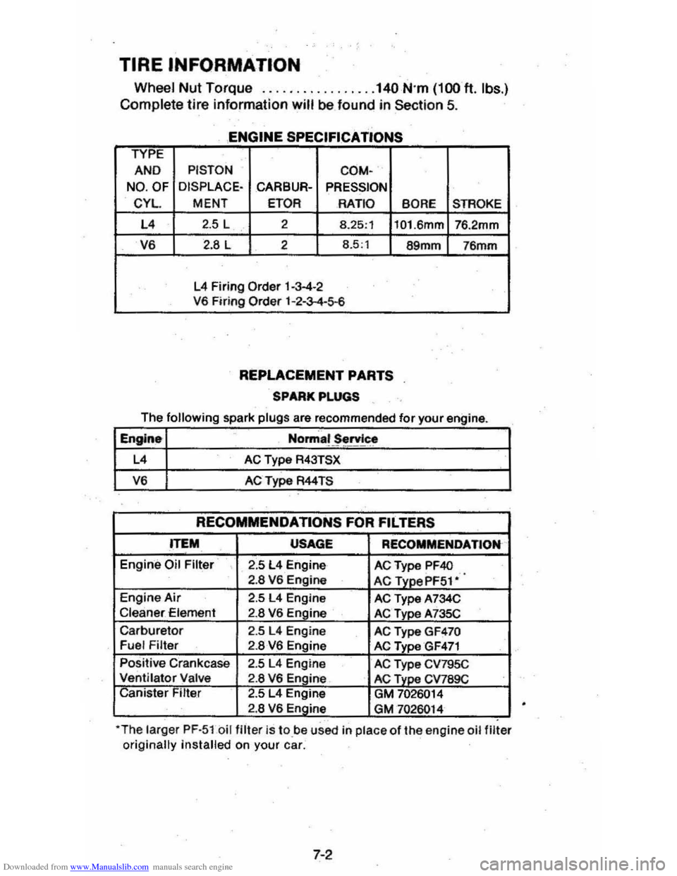
Wheel Nut Torque ................. 140 N'm (100 ft. Ibs.)
Complete
tire information will be found in Section 5.
ENGINE SPECIFICATIONS
TYPE
AND PISTON
COM-
NO . OF DISPLACE·
CARBUR-PRESSION
CYL.
MENT ETOR RATIO
BORE STROKE
L4 2.5 L 2 8.25,1
101.6mm 76.2mm
V6 2.8 L 2 8.5'1 89mm 76mm
L4 Firing Order 1-3-4-2
V6 Firing Order 1-2-3-4-5-6
REPLACEMENT PARTS
SPARK PLUGS
The following spark plugs are recommended for your eng'ine
Englne Norma~ ~rvlc.~
L4 AC Type R43TSX
V6 AC Type R44TS
RECOMMENDATIONS FOR FILTERS
ITEM USAGE RECOMMENDATION
Engin'e Oil Filter 2.5 L4 Engine ACType PF40 2.8 V6 Engine AC TYDePF51·
Engine Air 2.5 L4 Engine AC Type A734C Cleaner -Element 2.8 V6 Engine AC Type A735C
Carburetor 2.5 L4 Engine AC Type GF470 Fuel Filter 2.8 V6 Engine AC Type GF471
Positive Crankcase 2.5 L4 Engine AC Type CV795C Ventilator Valve 2.8 V6 Engine AC Type CV789C Canister Filte.r 2.5 L4 Engine GM 7026014 2.8 V6 Engine GM 7026014
I
*The larger PF·5lbil filter is tO,be used in place of the engine oil filter originally installed on your car.
7-2
Page 86 of 95

Downloaded from www.Manualslib.com manuals search engine FUSES AND CIRCUIT BREAKERS
The wiring circuits in your vehicle are protected from short circuits by a combination of fuses, circuit breakers; and fusible thermal links in the wiring itself. This greatly reduces
the hazard of electrically caused fires in the automobile.
The fuse junction box is located under the right side of the instrument panel.
The
headlight wiring is protected by a circuit breaker in the light switch. An electrical overload will cause the lights to go on an,d off, or in some cases to remain off. If this happens , have your headlight wiring checked right away. Besides a fuse, the windshield wiper motor is also protected by a circuit breaker. If the motor overheats, due to overloading caused by heavy snow, etc., the wiper ·will remain stopped until the motor cools. Be sure to have the cause of the over· loading corrected. Circuit breakers for power windows and power door locks are located on the bulkhead in the engine
compartment.
CIRCUIT RATING
Radio ........................................... 10 Amp.
Wiper
......... ......................... ......... 25 Amp .
Stop, .Rear & Front, Hazard Lamps, I.P. Indicators .. 20 Amp.
Dir.
Sig .. B.U. Lamps .............................. 20 Amp.
Heater,
AlC .............. ........................ 25 Amp .
Inst. Lamps, Radio Dial Lamp, Heater Dial Lamp, WIS Wiper Lamp, Cigarette Lighter & Ash Tray Lamp .. 5 Amp.
Gages Warning Lamps, Cruise Control , Brake Alarm,
Oil, Rear Defogger, Fuel Gage, Headlight Buzzer, Seat Belt Warning Buzzer, Temp., Gen., Idle Stop . 20 Amp.
Glove
Box Lamp, Dome Lamp, Luggage Lamp, Clock, Hood, Cigarette Lighter, Courtesy Lamps,
Key Warning .................................... 20 Amp.
Tail, Parking and
Side Marker Lamps, License Lamp 20 Am·p.
Choke Heater . . . . . . . .. .. .. . .. . . . . . . . .. . . . . 20 Amp .
Do
not use fuses of higher amperage rating than those recom· mended above.
Fusible Links are incorporated into the wiring system. These
are wires
of such a gage that they will fuse (or melt) before damage occurs to an entire wiring harness in the event of an electncal overload. See your Chevrolet Dealer if 1usible link replacement becomes necessary.
7-4
•
Page 89 of 95
Downloaded from www.Manualslib.com manuals search engine Catalytic Converter ..................................... . 5·2 C.4S~m . CHECK ENGINE Light.. .... : ..... . 2·18,5-2 2-18,5·2 Eldla~t Gas Csution ._ .... _ ...... . Fuel Requirements IGu, ._ .... ..
SENSOR Indie.tOt' .............. . Engin.
2· 2·2 2.18 •. 5.2
e.lts .... , ........ . (See M.int.n.nce SChedule) Br •• k·ln .... . ................................. 2-2 Cod ........... . Cooling .............................. .................... . Exh.ust Ges C.ution .................... .. Flil. to St.rt ........
,.,
5·5 2· 2·0 Flooct.d ,St.rting........... 2·g Fu.1 Recommend.tion (See "Fu.1'1 I~ntification ...... _........................................ 7-5 Jump St.rting ........................... 3·1 OiL.......... ....................... (5 .. "Oil, Engine'" Overh •• ting.. ....................... . 3.3 Speclflc.tions.. ............................................ 7·1 St.rtlng. Cold Weather ........................... ".. 2·9 St.rtlng (GI,oline). 2-8 T.mp.r.ture G.g..................... ................ 2-19 T.mp.ratur. Light ..................................... 2 ·17 Th.rmostlt. ............ ..................................... 5·7 Enolne Olt.. (S .. "Oil. Enginlt '')
Ethylane Gly<:ot AntifrNZe ......... 5·6 exhauSt Gn C.U1iOfI.._ .... Exhlu.t Sy.tem Inspection .. Exterior Fini.h C.ra .............. ............... .. F.bric Care ............................................ .. F.n, Halter" Air Cond ............................ .. FASTEN SEAT BELTS Light .......... ............. . FI.tener., Repllcemant Filte~ Air CI •• n.r ... .. Fini.h C.r ... . Finilh Olm.g • .. flammable Cle.ners ................................. . FI •• ,,-,.
HI,Zlrd Wlmi"il .. Turn Signll .............................. .......... .. Flood.d Engine, St.rting .. Floor Control ....
Fluid C.p.cili ................................. ............. .. FM Radio'
2· 2· 4·4 ' ·2 2·21 \·8 5·
5 ·8 4·4
4" 4·
3 · 2-0 2·. 2·13 ,. 2·24 Folding Se.ts ........ For.lgn Countries , Operation in .. 1·5 , 2·25 2·3 Four ·W.y Hazard FI.sher ..... .. FrHdom Bett.ry ......... .......... .. FrHing C.r Wh.n Stuck. ..................... . Fue' C.p... .. ............................ ............ .. Economy Tips .. Glge .................................... .. G, •• oUne Oct.ne R.ting ................................. ........ . Ov.~e •• Oper.tion ... Tlnk C.pecity .. Fu •• Ch.ft. ......
3· 5 ·. 3·'
, . 2·' 2 ·15 2·2 2 ·2 2·3 7·
7·4 Circuit Bre ... ers ....... _................. 7-" G.ga. Engin. Temper.ture 2 ·18 Fuel ..... ...... ............ ......... 2·15 Oil Pr •• sur ... T.chometer (Engin. Sp.ed) 2·17 2·19
7·7
Volt!"etftr .............. ................................. ....... 2·19 G.soIina ......... . .......... ....... _._... (Sa. "Fu.I") GEN (G.nerator) Livht 2:17 GI ... CI •• ning ................... _ .... .... _............. '·3
Glove 8011. ............................ _....................... 2 .1 6 Gu.rd Ao-irtSt T".ft ... ~...... 2-2 Hu.rd W.rning FI.sher.. 3·1 H.adlights Circuit are.ker.. 7_. Dimm.r Switch.. 2 ·1' Instrument P.n.1 Switch.. 2 ·15 lights ON Reminder 2 -19 He.ted R .. r Window......... ................ ........ 2·2,. H.ater/Alr CondltiOfler2·20, 2·21
High·e •• m H •• dlivhts........................ 2·7
Hitches , Tr.iI.r ............................. _......... 1.12 Hood L.tcha. Iln.ide B.ck Co~r) Hood R.l"H... (Inside B.ck Cowr) Horn ............................ ......... 2.13 HOT light ........ 2 ·17
Identificltion Numbers ........................... ....... 7·5
Ignition
K.V· .... · .. · ................ . Lock In Case of Emar;ency ... Indicator L~ht •.. Infenl Se'1I " Renr.in\.. Infl.tion Pres.ure. Tires Inl.ts, Air .............................. _ .... .. Inside R •• rviaw Mirror .. Instrum.nt P.n.1 &. Controls ...
\.
2·' 3 · (SH " lightS'') 1·10 5 ·11 2·20 '·3 2·15 Int.rior ApP41.r'nce C.re . ..................... ...... ,., Interior" Instrum.nt lights.. (See "lights'" J.ck Operation&. Stowlge.. 3·5. 3.8 Jump Stlrting .......... 3~" Keys ..... 1-1 Lan. Change 8t Turn Signals 2-6 L.p-Shoulde, Baits.. {See "Seat Belts ",
Latches
Folding S •• t~c"" .. 1·5 .2 ·25 Hood ....................... .. S •• tb.c", Front.. Leather Trim Cer ...
(Ins ide Back Cover) \·5
light.r, Clgar.ne ... lights BRAKE ......... .. Brights On ..... . Bulb Ch.rt.. CHECK ENGINE ... Dimmer SwitCh , Hndlight...
Electricel Svst.m (GEN) ENGINE ( O il & /or CI\o"e) Engin. TemP41f.ture (HOT) .. FASTEN SEAT BELTS .. GEN (EI.ctric.I System) ... Hazard W.rning FI.sher ... H •• dlight Circuit br.aker H •• dlight SwitCh ... H •• dlights On Reminder HEAT (Cat.lytic Convert.r) .. High·Beam Indicator HOT: .......................................... .. Instrum.nt P.n.1 Interior .......... . OIL (Pr.ssur.) .. Parking .... Se.t B.lt Remind.r ...
4 ·3
2 -20
2·17 2· 7 '·3 2 ·18. 5·2 2·' 2 ·17 2 ·11 2 ·17 \·8
2 ·17
3 · , .. 2 ·7,2·19 2-1Q 2·18, '5-2 2·7 . 2·19 2 ·17
2 -1E1 2·19 2·17 2·" ,1 ·8