1980 CHEVROLET CITATION check oil
[x] Cancel search: check oilPage 66 of 95
Downloaded from www.Manualslib.com manuals search engine NOTICE: You cannot read the correct fluid level if you have just driven the car for a long time at high speed, in city traffic in hot weather, or if the car has been pulling a trailer. Wait. until the fluid has cooled down (about 30 minutes).
Remove the dipstick located on the driver's side forward of the cowl. Carefully
touch the wet end of the dipstick to find out if the fluid is cool, warm or hot. Wipe
it clean and push it back in until the cap seats. Pull
out the dipstick and read the
fluid level.
• If it felt cool or warm (about room temperature), the level should be
between the dimples above the "Full" mark.
• If it was too hot to hold. the level should be at or in the hatched area.
Add just enough DEXRON-®n fluid to fill the transaxle. It takes only 0.5 liter
(one pint)to raise the level from "Add" to "Full" with a hot transaxle.
Do not overfill the transaxle. Overfilling can cause foaming and loss of fluid, which
could result in transaxle damage.
Automatic Transaxle Drain Intervals
Change the transmission fluid and change the filter (or clean the screen) as
outlined in Section
A of the Maintenance Schedule folder.
ELECTRIC FAN
CAUTION: Keep hands, tools, and clothing away from the angine cooling fan to help prevent personal injury. This fan is electric and can come on whether or not the engine is running. The fan can start automatically in response to a heat sensor when the ignition is in the "Run" position.
ENGINE COOLING SYSTEM
The coolant recovery system is standard. The coolant in the radiator expands with
heat, and the overflow collects in the recovery tank. When the system cools down,
the coolant
is drawn back into the radiator.
The cooling system was filled at the factory with a quality coolant that meets
GM Specification 1899-M. The cooling system is designed to use coolant (a mixture
of water and ethylene glycol antifreeze) rather than plain water. The coolant
solution should be used year round. It has many advantages, such as:
• provides freezing protection down to _37°C, (-34°P)
•
provides boiling protection up to 128QC, (262°P)
•
protects against rust and corrosion in the cooling system,
• maintains the proper engine temperature for efficient operation and emission
control, and
• allows proper operation of the coolant temperature light (or gage).
See Section A of the Maintenance Schedule folder to find out when the coolant
must
be replaced.
COOLING SYSTEM CARE
Check the cooling system at regular intervals, such as during fuel stops. You
usually do not need to remove the radiator cap to check the coolant level. Lift
the engine hood and look at the "see through" coolant recovery tank. When the
engine
is cold, the coolant level -should be at or slightly above the "Full Cold"
mark on the tank. When the engine has fully warmed up, the level should be at ')r slightly below the "Full Hot" mark on the tank. If the coolant level is low,
5-5
Page 67 of 95
Downloaded from www.Manualslib.com manuals search engine remOve tlie cap on the coolant ~ecove~y tank : Add to the tank enough of a 50 150 . mixture of w ater and a g ood quality eth)dene glycol antifreez e to bring the level
up to the .
proper mark. Put the cap bac k on the tank .
Certain
conditi ons; "Such as air trapped in the syste m, may affe ct the coolant level
in
the radiator. You sho uld ch ec k the co olant ·Ievel ·in the radiator while you
change the engine oil and the e ng ine is col d. Follow steps I , 8, 9 and 10 und er
"Coola nt Rep lacement" for the correct way to rt!move the radiator cap .an d add
. coolant.
If you have to add coola nt more than f our tim es a yea r (ei ther to th e recov ery
tank
or to the radiat or). see your dealer. for a. c oo lin g system chec k.
NOTICE: If the proper quality antifreeze is used, there is no .nee~ to add extra inhibltOf"s or additives which claim to improve the svstem .. They may be harmful to the proper operation. I)f the system.
Cooling System Service
The cooling syste m should be serviced at the intervals specifi ed inSection A of
the Maintenan ce Sch edule fold er as follows:
I. W ash the radiatqr cap .and filler neck with clean water. See step J of "Coolant
Replacement" to remove rapiator cap. .
2. C hec k the coolant level in the radiator and have it tes ted for freeze proteCtion . Add·· ethylene gly col antifreeze, if needed, to· m aintain freeze protecti on at -37'C(-34'F),
3~ Have ·the coOlin-g sys tem and radiat or cap tested fo r a press ure capacity of
105 kPa (15 psi) . If a repl acement cap is needed"Hse an AC ca'p,or an
equivalent · cap, designed fOl: coolant recovery system ·s and spe cified for your model;
4. Tighten all radiator hose clamps and heater hose clamps and inspect an hose s.
R
eplace the hose s if they are swollen, "checked" or otherwise worn .
NOTICE: Take care when tightenjng·the hose clemps at tMI radiator. Overtightening COUld. bend or collapse .the radiator fittings.
5. Clean the front. of the radiator core and air condit ioning condenser to re m ove
dirt and oth er·objects. Al so clean the auxiliary engine oil andlor transmission -fluid ' cooler if the vehicle has them.
Coolant, Replacement
At the interval s specified in Section A of the Maintenance Schedule folder, flu sh
a
nd refill the cool ing system as follows :
1. Remove the·radiat or·cap when the engin e is ·cool :
•
Turn . t he cap s lowly to the len until ·it reaches a " stop. " Do not press down while turning the cap.
• 'Wait until any rem aining press ure (indicated by a hissing sound) is
reliev ed. then press down on the cap an d continue turning it t(j the left.
CAUTION:· To help ~lVoid the danger of being ,burned, do not remove the radiator cap while the angine and radiator are still hot s.c.lding flutd and steam can be bk)wn out under pressure if the·cap is taken off.too soon.
2. Whe n the cap is re m oved, run the eng ine until the upper radiator hose is hot.
(This shows that the thermostat is open and the coola nt is flow ing through
the . system.)
5·6
•
Page 68 of 95
Downloaded from www.Manualslib.com manuals search engine 3. Stop the engine. Open the radiator drain valve to drain the coolant. (Drainage
may be speeded by removing the drain plugs in the block.)
4. Close the drain valve (install block drain plugs, if removed). Add water until
the system is filled and run the engine until the upper radiator hose is hot again.
5. Repeat steps 3 and 4 several times until the drained liquid is nearly colorless.
6. Drain the system and then close the radiator drain valve tightly. (Install block
drain plugs, if removed.)
7. Disconnect all hoses from the coolant recovery tank. Remove the tank and
pour out any fluid. Scrub and clean the inside of the tank with soap and water.
Flush it well with clean water,
then drain it. Reinstall the tank and hoses.
8. Add enough water and ethylene glycol antifreeze (meeting GM Specification
1899-M)to provide the required cooling, freezing, and corrosion protection. Use a solution that is at least 50 percent antifreeze, but no more than 70
percent antifreeze. Fill the radiator to the base of the filler neck and fill the
coolant recovery
tank to the "Full Hot" mark. Put the recovery tank cap back
on.
9. Run the engine, with the radiator cap removed, until the upper radiator hose
is hot.
10. With the engine idling, add coolant to the radiator until it reaches the bottom
of the filler neck. Install the radiator cap, making sure the arrows on the cap line up with the overflow. tube.
It is the owner's responsibility to:
• Maintain cooling system freeze protection at _37°C (_34°F) to ensure
protection against corrosion and loss of coolant from boiling. (A SO/50
mixture of water and ethylene glycol antifreeze will provide freeze protection
to ~ 37°C ore -34°P.) You should do this even if you don't expect freezing
temperatures.
• Add ethylene glycol base antifreeze that meets GM Specification 1899-M
when antifreeze
hasto be added because of coolant loss or for more protection
' against freezing at temperatures lower than _37°C (-·J4°P).
NOTICE: Do not use alcohol or methanol-base antifreeze. or plain water alone. in your vehicle at any time. They will boil at a lower pOint than that at which the hot light indicator (or temperature gage) works. and they do not provide proper protection against corrosion.
Radiator Pressure Cap
The radiator cap, a 105 kPa(15 psi) pressure type, must be installed tightly,
otherwise coolant may be lost and damage to engine may result from overheating.
Radiator pressure caps should be checked periodically for proper operation.
If
replacement is required, an AC cap is recommended.
Thermostat
The engine coolant temperature is controlled by a thermostat. It stops coolant flow
through the radiator until a preset temperature is reached. This thermostat is
installed in
the engine coolant outlet on the engine block. The same thermostat is used in both winter and summer. When a replacement is needed, AC~Delco parts
are recommended.
5-7
Page 70 of 95
Downloaded from www.Manualslib.com manuals search engine CAUTION: If the air cleaner is removed during repair or maintenance, be sure to . put It back on correctly. If the air cleaner is not correctly installed, there could be II fire In the engine compartment (if there should happen to be a backfire), or other engine malfunction.
Power Steering System
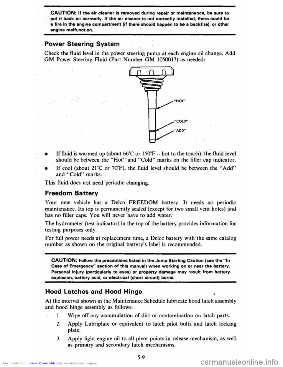
Check the 'fluid level in the power steering pump at each engine oil change. Add GM :Power Steering Fluid, (Part Number GM 1050017) as needed:
, • Ifnuid is warmed up (abo ut 66°C or lSO"F --hot to the to uch), the fluid level
should be between the "Hot" and "Cold" marks on the filler cap indicat or.
• If cool (about 21°C or 70° F), the fluid level should be between the "Add" and "Cold" marks.
This fluid
does not need ' periodic changing.
Freedom Battery
Your new vehicle has a Delco FREEDOM battery. It needs no periodic
maint enance . Its
lOp is permanently sealed (except for two small vent holes) and
has no filler caps. You will never have to add water. .
The hydrometer (test indicat or) in the top of the battery provides information for
testing purposes only.
For full power needs at repla cement time, a Delco battery with ,the same catalog
number as shown on the original banery's label
is recommended.
CAUTION: FoUow the precautions listed in the Jump Starting Cautton {see the "'n Case of Emergency''' section o"f this manual, when working on or near the battery.
Personal injury (particularly to eyes) or property damage may result from battery explosion, battery acid, or electric.1 (short circuit) burns.
Hood latches and Hood Hinge
At the interval shown in the Maintenance Schedule lubricate hood latch assembly
and hood hinge assembly as follows :
1 . Wipe off any accumulation
of dir.t or contamination on latch parts.
2. Apply Lubriplate or equivalent to latch pilaf bolts and latch loc king
plate .
3. Apply light engine oil to all pivot points in release mechanism, as well
as primary
and secondary latch mechanisms.
5-9
Page 83 of 95
Downloaded from www.Manualslib.com manuals search engine . SECTION 7
SPECIFICATIONS
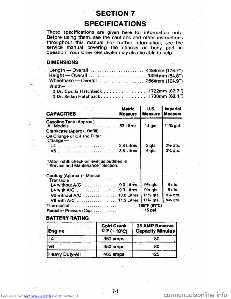
T hese specifications are given here for information on ly . B efore using them, see the cautions and other instructions
throughout this manual. For fu.rther information , see the
service manual covering the chassis or body part in question. Your Chevrol et dealer may also be abl e to help.
DIMENSIONS
Length -Overall ......... , •.... , •...... 4488mm (176 .7")
He igl;lt -Overall ......................... ':394mm (54.8 ") Wh eelbase "-Overall ................... 2664mm (104.9")
Width-2 Dr. Cpe. & Hatchback .· ............. 1722mm (67.7") 4 Dr. Sedan Hatchback.. . . . . . . . . . . . .. 1730mm (68.1 ")
Metric U .S .
CAPACITIES Mea .... .... .ur.
Gasoline rank (Approx.) All Models .................... 53 litres 14 gal.
Crankcase (Approx . Refililt Oil Change or Oil and Filter Change-
L4 ........ ........... '. ' .. ... 2.8 Litres 3 qts .
V6 . . . . . , . . . . . . . . . . . . . . . . . . . . . . 3 :8 Litres 4 qt • . .
t After refill ; check oil kwel as outlined in "Service and Mantenance " Section .
Cooling (Approx.)· Manual Tran sa x le L4 without AlC ..... . , .. .
L4 withA/C .... ... ........... .
V6 without AlC ...... ...•...... V6 with AlC ....... . Thermostaf.-.-:~-~-. -....... : ....... .
Radiator Pressure Cap
BATTERY RATING
9.0 Litre. 911 •. qls. 9.3 Litres 9¥4 qts.
to.8 Litres 1'1'12 qts.
11.2 Litres 11¥ " .c:Jts. 195"1' (91·e) 15 pal
Imperial
Me.sure
11~gal.
21f2qts .
3Ve qts.
8 qt •.
8 qts. 9V .. qts.
g¥ .. qts.
colci Crank 25 AMP Reserve
Engine .. O"F (-l8"C) Capacity Minutes
L4 350 amps 60
V6 350 amps 80
Heavy Duty "AIi 465 amps 125
7-1
Page 86 of 95

Downloaded from www.Manualslib.com manuals search engine FUSES AND CIRCUIT BREAKERS
The wiring circuits in your vehicle are protected from short circuits by a combination of fuses, circuit breakers; and fusible thermal links in the wiring itself. This greatly reduces
the hazard of electrically caused fires in the automobile.
The fuse junction box is located under the right side of the instrument panel.
The
headlight wiring is protected by a circuit breaker in the light switch. An electrical overload will cause the lights to go on an,d off, or in some cases to remain off. If this happens , have your headlight wiring checked right away. Besides a fuse, the windshield wiper motor is also protected by a circuit breaker. If the motor overheats, due to overloading caused by heavy snow, etc., the wiper ·will remain stopped until the motor cools. Be sure to have the cause of the over· loading corrected. Circuit breakers for power windows and power door locks are located on the bulkhead in the engine
compartment.
CIRCUIT RATING
Radio ........................................... 10 Amp.
Wiper
......... ......................... ......... 25 Amp .
Stop, .Rear & Front, Hazard Lamps, I.P. Indicators .. 20 Amp.
Dir.
Sig .. B.U. Lamps .............................. 20 Amp.
Heater,
AlC .............. ........................ 25 Amp .
Inst. Lamps, Radio Dial Lamp, Heater Dial Lamp, WIS Wiper Lamp, Cigarette Lighter & Ash Tray Lamp .. 5 Amp.
Gages Warning Lamps, Cruise Control , Brake Alarm,
Oil, Rear Defogger, Fuel Gage, Headlight Buzzer, Seat Belt Warning Buzzer, Temp., Gen., Idle Stop . 20 Amp.
Glove
Box Lamp, Dome Lamp, Luggage Lamp, Clock, Hood, Cigarette Lighter, Courtesy Lamps,
Key Warning .................................... 20 Amp.
Tail, Parking and
Side Marker Lamps, License Lamp 20 Am·p.
Choke Heater . . . . . . . .. .. .. . .. . . . . . . . .. . . . . 20 Amp .
Do
not use fuses of higher amperage rating than those recom· mended above.
Fusible Links are incorporated into the wiring system. These
are wires
of such a gage that they will fuse (or melt) before damage occurs to an entire wiring harness in the event of an electncal overload. See your Chevrolet Dealer if 1usible link replacement becomes necessary.
7-4
•
Page 88 of 95
Downloaded from www.Manualslib.com manuals search engine Air Cleaner ...... . Air Conditioner
Automat ic ............ . Malnt.nance Air Pre •• ur •. Tire .... A ir Vents ..... Alternator (GEN) Light .. Aluminum Car •.. AM or AM·fM R.dios ..... Antifra.z . ..... ......... .......... . App.aranc. Car ...... Ashtrays & l ighters. Assi.tance. Owner .. Autom.tic DOOf lOCks
Autom.tic: Trann.l. Malnt.mimc. Operation .. Operating Tip$ ..... Axl. , Drive .. Sabies, Reatraint of . San Joints S.ttary
5-8
2 -
22 5·10 5·11 2·21 2·17 .-. 2·24 (S •• "Coolant") '-1 2-20 0-1 1-2
5-. ,-a 2 ·10 5-8 1·10 5-8
Em.rgency SIIHting.. 3-1 Fr •• dom .... 5·9 G •• Caution... 3-1 ; GEN Light ... 2·11 T •• t Indicator... 5·9 Befortl Oriylng Your V.hicle ,., Belt •. Seat .... M. (S .. "Seat Baits",
Blower, H.at.r &. Air Cond.... 2-20 Body Oamag... 4·4 Brak.s Adjustment P.dal Trav.l Traller 'Towing .. Warning Light Bre.ka,., Circuit
Break·ln Period, N.w V.hicl •... Bright Headlights .....
2-14 2·14 1 -11 2·17 7-4 2-' 2·7,2·14 4-4 1 -3.7·4 1-12 3-6 {S •• "Sound"l 2·18, 5-2
Bright Metal CI.aning ......... .. Bl,llbs lit Fu ••• Bumpe ... lit Hitch ••.. 81,1mper Jack Operetion Bun.r •.. C·4 Syst.m .. C •• Coolant RaeoV.ry Tenk .. FI,I.I. Powar St •• ring .... R.diator ..... . Cap.city. Cargo W.ight ... .•. Cap3Cme •. Fluid .. C.r Br.ak·ln Period , N.w ..... . C.r Chemic. I ......... .. C.rbon Monoxid. Caution
'-5 Inside Back Cover .-a '-7 6-12 7-1 2-' '-7 '-1 C.r. &. CI.aning, Appear.nce 4-1 C.rgo Capacity. 5-10 Cargo on Roof, C.rrying.. ......... ............... 1·3 CargoR.ck, Roof ..... 2·29 Cargo Coyer .. ................ ........... 2-27 CATALYST Indic.tor..... 2 ·18 C.t.lytic Conv.n.r C ·4 System ......... . Chains, Tir • ..... Ch.nging Whe.'s • Tiras .. Ch.rging Systam Indicator .... CHECK ENGINE light..
2·18,5--2 5·14 3-6 3-2 2-18, 5-2
7-6
Checklist. Driver ....... . Child Seats lit Ra.traint •.. Chrome Protection .. Cigarette lightar .... Circuit Breakars . Citizens Band Radio ... " .... " .... " .. M ••••••• Cleening .. Clock
Cloth Trim Car." .. Clutch Pedal Adjl,lstment.. .. Cold Welther Stlrting ..... Compla int Procedure ..
1-1 1-10 .-. 2·20 7-' 2·2 ~ 4-1 2·20 .-, 5-8 '-a 6-1
Conditionar, Air ....... (See "Air Conditi on.r") Con.umer Relations... 6-1
Cony.)! Mirror ... C ooling System Antifraet. ICoolant, .. Overheating .. Recovary Tank .. S.rvice .. Thermostat .. CorrOSion Protection Countries. Oper.ting in Foraign ..... Cruise Control .. Cu.tomer Sarvice .. Oamage. Sheet M.tal...-. D.fogger. Rear Window. Defro.hlT , Windshiflld .. Oalay Wipers .. Descend .ing a Grade Trail.ring .. Dimen.ion. Dimmer Switch, H.adlight Dipsticks
Engine Oil .. Power Staering .. Diractional Sign." .... . Oi.c Br~ ••.. Door lock ......
Drrve lOOe
1-3
'-5 3-3 5-S '-5 5-7 .-. 2 -3 2·12 6-1 '-5 2-21 2 -20, 2·23 '-7 '-8 1-11 7-1 2-14
'-3 .-a ,-u 2·1S 1-2 5-8 Driver Checklist.... 1·1 Driving Down Steep Gr.de........ 2·9 In Ou.ty Ar......... 5·3 on Slippery Surfaces ....... .......... ,.... 2·9 Ec;Gnomy Tips , Fu" 2·4 Electric-Powered Option...... (See "Power")
Ele<:tricel System 8IttMY ... ... .
Bulbs ...... .
Circuit Brlak.rs. , .... GEN (Glnerator) light ...... Jump Scarting .. .. Sparil Plugs .. Voltm.ter ... Erne:rg.ncy , In Ca •• of Brak. Warning Light Engine Hot light .. Freeing Vahicle When Stuck ... Hazard Warning Fla.h.r .... J.cking ..... Jump 51anlng._. Towing Clr. Emission Caution .................................. . Emi .. ion Control CAT AL YST Indicator
5-S 7-3 7-. 7-' 2·17 3-1
7-2
2·19
2·17 2·17 3-7
3-1
3 ·4 .3·5 3-1
3-7
'-1
2·19
,
Page 89 of 95
Downloaded from www.Manualslib.com manuals search engine Catalytic Converter ..................................... . 5·2 C.4S~m . CHECK ENGINE Light.. .... : ..... . 2·18,5-2 2-18,5·2 Eldla~t Gas Csution ._ .... _ ...... . Fuel Requirements IGu, ._ .... ..
SENSOR Indie.tOt' .............. . Engin.
2· 2·2 2.18 •. 5.2
e.lts .... , ........ . (See M.int.n.nce SChedule) Br •• k·ln .... . ................................. 2-2 Cod ........... . Cooling .............................. .................... . Exh.ust Ges C.ution .................... .. Flil. to St.rt ........
,.,
5·5 2· 2·0 Flooct.d ,St.rting........... 2·g Fu.1 Recommend.tion (See "Fu.1'1 I~ntification ...... _........................................ 7-5 Jump St.rting ........................... 3·1 OiL.......... ....................... (5 .. "Oil, Engine'" Overh •• ting.. ....................... . 3.3 Speclflc.tions.. ............................................ 7·1 St.rtlng. Cold Weather ........................... ".. 2·9 St.rtlng (GI,oline). 2-8 T.mp.r.ture G.g..................... ................ 2-19 T.mp.ratur. Light ..................................... 2 ·17 Th.rmostlt. ............ ..................................... 5·7 Enolne Olt.. (S .. "Oil. Enginlt '')
Ethylane Gly<:ot AntifrNZe ......... 5·6 exhauSt Gn C.U1iOfI.._ .... Exhlu.t Sy.tem Inspection .. Exterior Fini.h C.ra .............. ............... .. F.bric Care ............................................ .. F.n, Halter" Air Cond ............................ .. FASTEN SEAT BELTS Light .......... ............. . FI.tener., Repllcemant Filte~ Air CI •• n.r ... .. Fini.h C.r ... . Finilh Olm.g • .. flammable Cle.ners ................................. . FI •• ,,-,.
HI,Zlrd Wlmi"il .. Turn Signll .............................. .......... .. Flood.d Engine, St.rting .. Floor Control ....
Fluid C.p.cili ................................. ............. .. FM Radio'
2· 2· 4·4 ' ·2 2·21 \·8 5·
5 ·8 4·4
4" 4·
3 · 2-0 2·. 2·13 ,. 2·24 Folding Se.ts ........ For.lgn Countries , Operation in .. 1·5 , 2·25 2·3 Four ·W.y Hazard FI.sher ..... .. FrHdom Bett.ry ......... .......... .. FrHing C.r Wh.n Stuck. ..................... . Fue' C.p... .. ............................ ............ .. Economy Tips .. Glge .................................... .. G, •• oUne Oct.ne R.ting ................................. ........ . Ov.~e •• Oper.tion ... Tlnk C.pecity .. Fu •• Ch.ft. ......
3· 5 ·. 3·'
, . 2·' 2 ·15 2·2 2 ·2 2·3 7·
7·4 Circuit Bre ... ers ....... _................. 7-" G.ga. Engin. Temper.ture 2 ·18 Fuel ..... ...... ............ ......... 2·15 Oil Pr •• sur ... T.chometer (Engin. Sp.ed) 2·17 2·19
7·7
Volt!"etftr .............. ................................. ....... 2·19 G.soIina ......... . .......... ....... _._... (Sa. "Fu.I") GEN (G.nerator) Livht 2:17 GI ... CI •• ning ................... _ .... .... _............. '·3
Glove 8011. ............................ _....................... 2 .1 6 Gu.rd Ao-irtSt T".ft ... ~...... 2-2 Hu.rd W.rning FI.sher.. 3·1 H.adlights Circuit are.ker.. 7_. Dimm.r Switch.. 2 ·1' Instrument P.n.1 Switch.. 2 ·15 lights ON Reminder 2 -19 He.ted R .. r Window......... ................ ........ 2·2,. H.ater/Alr CondltiOfler2·20, 2·21
High·e •• m H •• dlivhts........................ 2·7
Hitches , Tr.iI.r ............................. _......... 1.12 Hood L.tcha. Iln.ide B.ck Co~r) Hood R.l"H... (Inside B.ck Cowr) Horn ............................ ......... 2.13 HOT light ........ 2 ·17
Identificltion Numbers ........................... ....... 7·5
Ignition
K.V· .... · .. · ................ . Lock In Case of Emar;ency ... Indicator L~ht •.. Infenl Se'1I " Renr.in\.. Infl.tion Pres.ure. Tires Inl.ts, Air .............................. _ .... .. Inside R •• rviaw Mirror .. Instrum.nt P.n.1 &. Controls ...
\.
2·' 3 · (SH " lightS'') 1·10 5 ·11 2·20 '·3 2·15 Int.rior ApP41.r'nce C.re . ..................... ...... ,., Interior" Instrum.nt lights.. (See "lights'" J.ck Operation&. Stowlge.. 3·5. 3.8 Jump Stlrting .......... 3~" Keys ..... 1-1 Lan. Change 8t Turn Signals 2-6 L.p-Shoulde, Baits.. {See "Seat Belts ",
Latches
Folding S •• t~c"" .. 1·5 .2 ·25 Hood ....................... .. S •• tb.c", Front.. Leather Trim Cer ...
(Ins ide Back Cover) \·5
light.r, Clgar.ne ... lights BRAKE ......... .. Brights On ..... . Bulb Ch.rt.. CHECK ENGINE ... Dimmer SwitCh , Hndlight...
Electricel Svst.m (GEN) ENGINE ( O il & /or CI\o"e) Engin. TemP41f.ture (HOT) .. FASTEN SEAT BELTS .. GEN (EI.ctric.I System) ... Hazard W.rning FI.sher ... H •• dlight Circuit br.aker H •• dlight SwitCh ... H •• dlights On Reminder HEAT (Cat.lytic Convert.r) .. High·Beam Indicator HOT: .......................................... .. Instrum.nt P.n.1 Interior .......... . OIL (Pr.ssur.) .. Parking .... Se.t B.lt Remind.r ...
4 ·3
2 -20
2·17 2· 7 '·3 2 ·18. 5·2 2·' 2 ·17 2 ·11 2 ·17 \·8
2 ·17
3 · , .. 2 ·7,2·19 2-1Q 2·18, '5-2 2·7 . 2·19 2 ·17
2 -1E1 2·19 2·17 2·" ,1 ·8