1980 CHEVROLET CITATION check engine light
[x] Cancel search: check engine lightPage 35 of 95
Downloaded from www.Manualslib.com manuals search engine • This warning light docs no t do away with the need f or ~rake il),s.-pectio n and
maintenanc e. The brake fluid level must be checked regularly . See yo ur
Maint enance Schedule folder for
other brake checks.
If th e light comes on and stays o n when the ig nition key is on, after the brak e
pedal ha s been firmly pushed do wn, it may mean that there is somethin g wrong
wit'h one part of the brake system.
Wh at 10 do:
I. C heck to see that the pa rkin g brake has been released. If it has been ...
2. Pull off the road and sto p ca refully. And rememb er that:
• Stopping di stan ces may be longer .
• You may ha ve to pu sh hard er on the ped al.
• The pedal may go down farther {han no rm al.
3. Tryout the brake s by sta rrin g and stopping on the ro ad shoulder--then :
• If you judge it to be safe, drive cautiously at a safe speed to the neat est
dealer for repair , or
• Have vehicl e to w ed to dealer for repair .
Co ntinu ed dri ving with o
ut getting necessary re p a ir s co uld be dangerou s.
"EMISSIONS" INDICATOR
On so me cars, the word "EMISSIONS" is des ig ned to appear in a window in the spe ed om eter faceat certain int~rvals. This is a reminder that maintenan ce se rv ice
mu st
be performed on your ca r. One of two type s' o f se rvice is required :
• On cars equipped with the C-4 System, the oxygen sensor must be replaced with · a new sensor, or
• On
ca rs without the C -4 System, the cataly st in the catalyti c converter must
b e c han ged.
In either case, see yo ur Chl!~rolet dealer fo r se rvice when the "EMISSIONS "
indicat or appears. .
F or more information , see
"C-4 (Computer Contr olled Catalytic Conv erte r)
Syste m " and "Catalyti c Co nverter," both in "Service and Maintenance," Section
5 of thi s manual.
"CHECK ENGINE" LIGHT
If yo ur car has the C-4 System, a "CHECK ENGINE" light on the instrum ent
panel is des ig ned t o come on
during engine starting to le t y ou know th e bulb is
w orkin g. (The light will sla y o n a short time after th e e ngine s tarts .) If th e light
c o m es on whil e
drivin g, se rv ic e to the emi ssion contr ol sy stem may be re quired . Sc:e your Chevrolet deal er as soo n as: possible fo r an in spec tion of the sy ste m .
COlltinu ed driving without having [he C-4System serviced could eventually cause
d am age to the emission control system. It could also affect fuel economy and
driv ability.
See also '; C-4 (Comput er Co ntrolled Catalytic Converter) System" in ;'Ser vic e a nd
Mainte n ance, " Section 5 o f this manual.
Tachometer
The opti onal Tachomet ers indi cat e the speed of th e e ngin e in revoluti ons pe r minute. The indicated number, tim es ](x>o .. gives the engine s peed. Operatil.lg th e
engine w ith the tachom ete r r eading in the color- coded high ~peed area could lead to s~rious engine damage. The re are two tachom .e ter s us ed in the car depending on the e ngine option install ed in your car.
2-18
Page 36 of 95
Downloaded from www.Manualslib.com manuals search engine Engine Temperature Gage
This gage indicat~cCX?lant temperature which will vary with air temperature and
operating condition~, The ignition must be on for accurate readings. Hard driving
or prolonged idling In very hot weather will cause the pointer to move beyond the center of the band; Should pointer move to the Red Zone, see "Engine Cooling
System" on page 3-3.
Oil Pressure Gage
The oil pressure gage indicates the pn;ssure at which oil is being delivered 10 the various parts of the engine requiring lubrication. Pressures registered by the gage
I11.!lY vary according to outside air temperatures or weight of oil being used. Oil
pressure of a cold engine ~ing operated at a given speed will be somewhat higher
than when the engine is at normal operating temperature at the same speed .
. Prolonged high speed operation on a hot day at the given speed will result in somewhat lower oil pressure readings. Readings of 30 to 40 psi (205 to 275 kPa)
mny
be considered normal during moderate road speeds of 35 to 40 mph (55 to
60 km/h) \\lith the engine at proper operating temperature. Gage readings which
are
consistently high or Im\l under these conditions may indicate lubrication system
When the engine is operating, the voltmeter indicates the electrical system voltage.
During minimum electrical load, the pointer will read to the right of the center.
As the electrical load is increased,
or in stop-and-go driving, the pointer will rotate
to the left. A meter reading continuously in
the left or right red zone indicates
an electrical system
failure .. Cause of the failure should be determined and corrected~
Light Switch
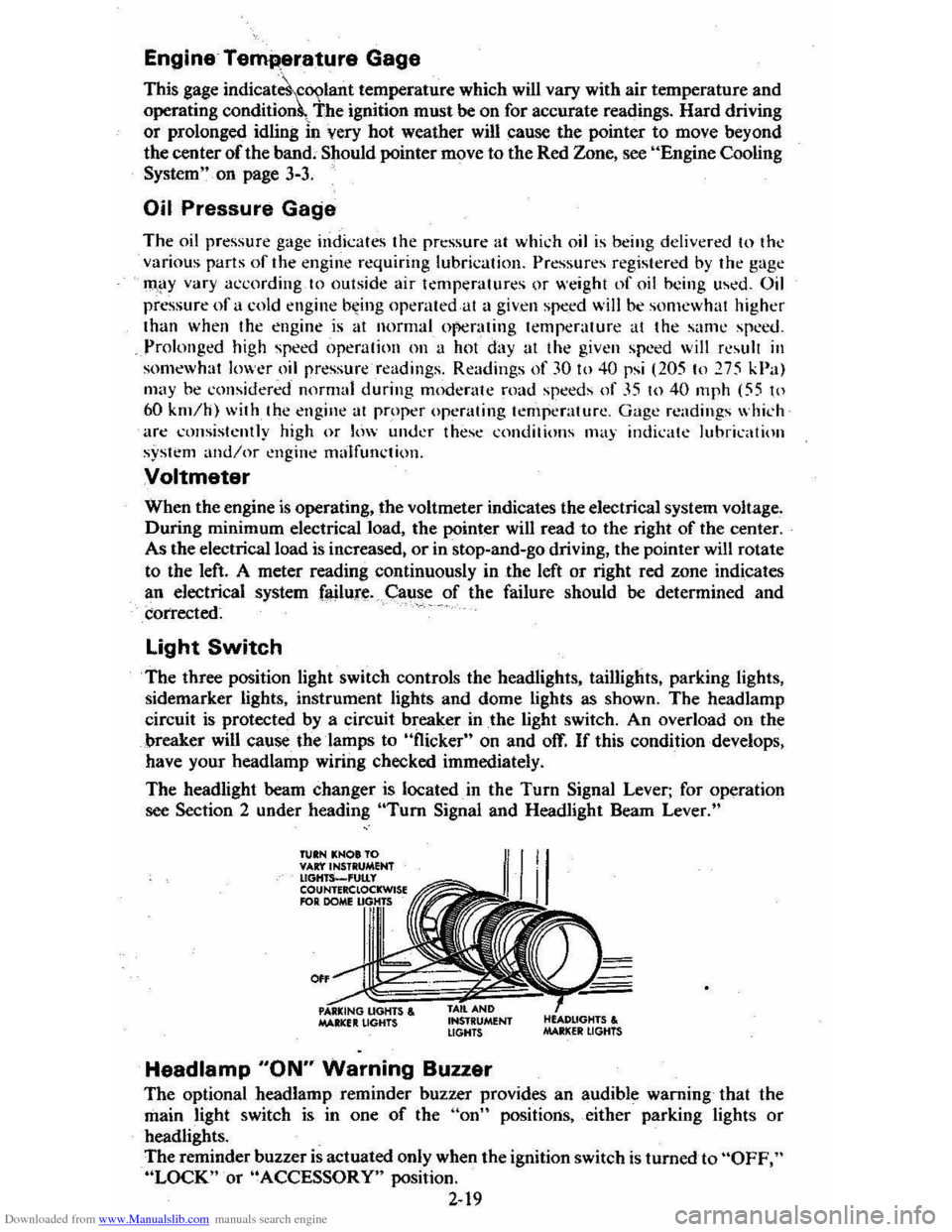
The three position light switch controls the headlights, taillights, parking lights,
sidemarker lights, instrument lights and dome lights as shown. The headlamp
circuit is protected by a circuit breaker in
the light switch. An overload on the
breaker will cause the lamps to "flicker" on and off. If this condition develops,
have your headlamp wiring checked immediately.
The headlight beam changer is located. in the
Turn Signal Lever; for operation
see Section 2 under heading "Tum Signal and Headlight Beam Lever."
TUIN KNOt TO VAr:t'INSTRUMENT lIGHTS_'UtLy COUNTERClOCKWISE RlR DOME
0"
MAltlCfIt LIGHTS , INSTRUMENT LIGHTS
Headlamp "ON" Warning Buzzer
The optional headlamp reminder buzzer provides an audible warning that the
main light switch is in one
of the "on" positions, either parking lights or
headlights.
The reminder buzzer
is actuated only when the ignition switch is turned to "OFF," "LOCK" or "ACCESSORY" position.
2-19
Page 46 of 95
Downloaded from www.Manualslib.com manuals search engine Insta"ation
To install the cargo cover:
1. Insert the left hinge pin in the bracket attached to the body of the car.
2. Slide the release lever to the right to engage hinge pin in the 'bracket. See figure
B.
3. Move the lever up to lock the cover in place.
4. Reconnect the rubber 'lifting cords.
STOWING THINGS IN (OR ON) THE CAR
CAUTION: luggage or other cergo should not be piled higher than the seatbacks, When at all possible, luggage or cargo should be C8rrifHj in the trunk area. The filler panel or cargo cover, between the rear 88atback and the rear window should not be used to carry objects-even those that are small and light. All nems should be secured in place. This will help keep such things from being thrown about and Injurying people in the car during an accident. Cargo weight whether inside or on the roof, should be positioned as evenly as possible from front to rear.
ROOF LUGGAGE CARRIER
The optional roof luggage carrier is designed to allow loading of items onto the
roof
of your car. The roof luggage carrier does not increase the total load carrying
capacity of th e car , as shown opposite "Max Load" on the Tire Placard located
on the left front door. Be sure the total weight of the cargo on the roof, plus the
weight
of the cargo and passe ngers inside the car, plus the tongue load of any
trailer you are towing does
,1;10t exc_eed this "Max Load" vehicle capacity weight. See Section 5, page "5-11 for more information on Vehicle Loading . Also see the
infonnation on Trailer Towing
in Section 1 of this manual . if needed .
NOTICE:To helpayoid pOSSible damage, do not exceed 70 kilograms (1 50 pounds), cargo weight on the roof. Position the cargo in the luggage carrier as evenly as: pOssible. If carrying long items, never exceed car length and fasten such loads securely at the front and rear of the car, as well as to the luggage rack.
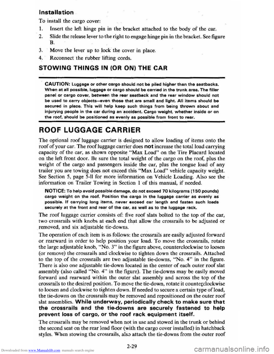
The roof luggage carrier consists of: five roof slats bolted to the top of the car,
two crossrails with knobs at each end th~t allow the crossrails to be adjusted or removed, and six' adjustable tie-downs.
The operation
of each item is as follows: the crossrails are easily adjusted forward
or rearward in order to help position your load. To move the crossrails , rotate
the large adjustable knob, ··No. 3" in the figure above. counterclockwise to loosen
(or remove) the crossrails and 'clockwise to tighten down the cros srails. Attached
to the top
of the crossrails are two adjustable tie-downs, "No.4" in the figure.
Ther e is also one adjustable lie-down located in the center of each outer roof slat
assembly (also called
"No.4" in the figure) . The tie-downs may be easily moved
forward and rearward within the outer slat assembly and across the top
of the
crossrails to the desired position.
To move the tie-down . rotate it countetclockwise
to loosen and clockwise to tighten down. If needed to sec ure a certain type of lead,
the tie-downs on the
crossratls may be removed and repos itioned on the outer roof
slat assemblies. While underway, periodically check to make sure that
the crossrails and the tie-downs are securely fastened to help
prevent loss of cargo, or the roof rack equipment itself.
The crossrails may be removed when not in use and stowed in the trunk or behind
the second seat on the rear load floor (with the carg o cover installed) in hatchback
style
s. When stowing the cressrails, al5..1 attach the tie-downs from the outer roof
2-29
Page 49 of 95
Downloaded from www.Manualslib.com manuals search engine • To lessen the chance of an explosion, never expose a battery to open flames
or electric sparks. Also do not smoke near a ,battery. Batteries give off a gas which is flammable and explosive.
• To lessen the risk of injury incase an explosion does occur, wear eye protection or shield your eyes when working near any battery. Do not lean over a battery.
• Do not allow battery fluid to contact eyes, skin, fabrics, or painted surfaces
because battery fluid is a corrOsiVe acid. Flush any contacted area with water immediately a,nd thoroughly. Also get medical help if eyes are affected.
• To lessen the riskofa short circuit. remove rings, metal watch bands and otl:ler metal jewelry. Also do not allow metal tools to contact at the same time the positive battery terminal (or any metal connected to this terminal) and any other metal em either "ehicle. Make certain when attaching the jumper cable clamps rothe positive terminals of the batteries that neither clamp contacts any other metal.
• This
vehicle has a 12 volt battery and a negative ground electrical system. Make sure that the other vehicle als~ has a 12 volt battery and that the negative terminal, is .'grounc::ted(attached to a metal, part of the vehicle). Its owner's manual may give you that information, If unsure of the other vehicle's voltage (or if the voltage and/or ground on the other vehicle are different from your vehicle). do not try to jump startas personal injury or severe damage to electrical and electronic parts may result.
• If the discharged battery has filler caps. check the fluid level. ( 00 not check with an Op~tn flame and db not smoke .) Add clear drinking water to the proper level if low, and replace the caps before jump starting.
I. Position, the vehicle with'the good (charged)ba,.ttery so that the jump starting
cables will reach.
Do not let the vehicles t"ouch.
2. Turn off all electric motors and accessories in both vehicles. Turn off all lights
except those needed to protect the vehicles or light up the work area. Turn
off the ignition, apply the parking brake firmly, and shift the automatic transaxleto "p"o.?ark) (manual transaxle to "N"(Neutral) in both vE-hicles.
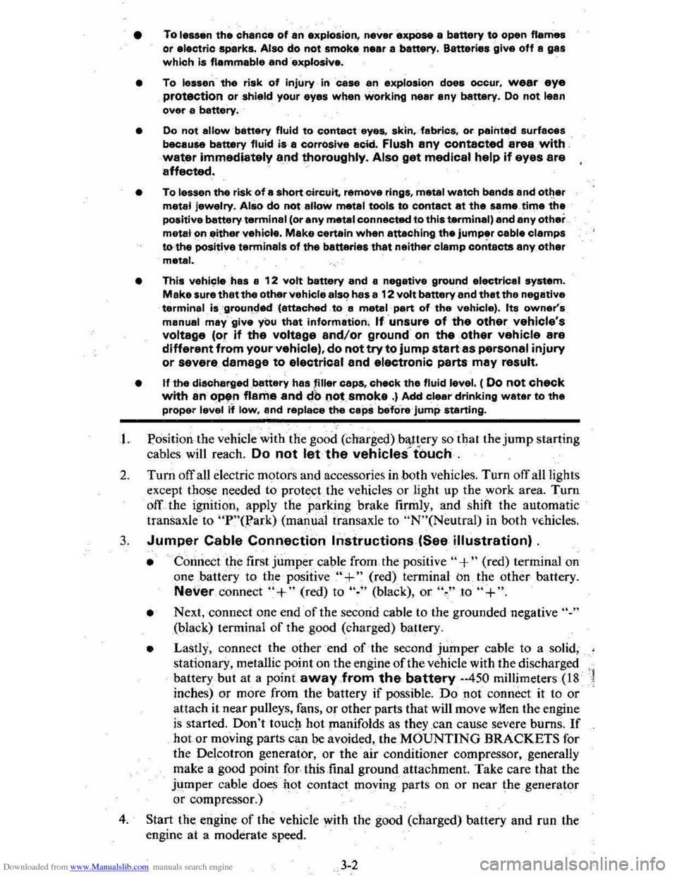
3. Jumper Cable Connection Instructions (See illustration) .
• Connect the first jumper cable from the positive" +" (red) terininal on
one battery to the positive "+" (red) terminal on the other battery.
Never, connect "+" (red) to "~" (black), or '\" to "+".
• Next, connect one end of the second cable to the grounded negative "."
(black) tenninal of the good (charged) battery.
• Lastly, connect the othetend of the second jumper cable to a solid,
stationary, metallic point on the engine of the vehicle with the discharged
battery but at a
point away from the battery --450 millimeters (18 '1
inches) or more from the battery if possible. Do not connect it to or attach it near pulleys, fans, or other parts that will move wHen the engine
is started. Don't touctt hot manifolds as they _can cause severe burns. If hot or moving parts can be avoided, the MOUNTING BRACKETS for
the Delcotron generator,
or the air conditioner compressor, ,generally
make a good point for-this final ground attachment. Take care that the
jtimper cable does
hot contact moving parts on or near the generator
or compressor.)
4. Start the engine of the vehicle with the good (charged) battery and run the
engine at a moderate speed.
3-2
Page 51 of 95
Downloaded from www.Manualslib.com manuals search engine • pull over-to a 'safe p'late and stop (he car:-=Set the parking brake and shift to "P"(Park) (with a manual transaxle. shift to Neutral first, then set the parking
brake).
• DON'T TURN OFF THE ENGINE AND DON'T INCREASE THE ENGINE SPEED~ Let the engin e run at normal idle speed for two or three
minutes.
If the
''TEMP'' light still doesn't go off (or the gage needle doesn't start to drop) , NOW TURN OFF THE ENGINE and proceed as follows.
CAUTION: Keep henda, tools end clothing awey from'the engine COOling fen to help prevent personal Injury. This fen ia electric end can come on whether or not the eR8ine is runnirl'jJ. The fan Cen etert eutomatically in reapon .. to a heet ~, wrth the ignitkNl in ~Run."
• Lift the engine hood. Look at the coolant level.in the "see through " coolant
recovery tank. The coolant level should be at or above the "Fun Hot" mark
o n the tank.
If it looks like the coolant is boiling, wait until it stops before
proceeding You should :not need to remove the radiator cap to check the
coolant level and it can be dangerous if the coolant is still hot. See the
following Caution.
CAUTION: To help avoid the dange, of being burned:
• cia not remove the coolent recov.ry tank cap while the coolant is boiling.. and
• cia not remove the .rad~:_c.p white the engine end radiator are atill hot.
Scelding fluid and ateam can be blow, Qut under presau,.. If either cap ia taken off too soon.
• If the coolant level is low:
• look for leak s at the radiator hoses and connectio ns, heater hoses and
connections. radiator, and water pump.
See that the water pump belts
are not
brok~ or otT the pulleys and that the fan runs when the engine is running and theUTEMP" light ison (or the gage needle is in the
warning zone).
• add coolant to the recovery tank.
If the level in the recovery tank is at the correct level and the "TEMP" light (gage) still comes on, air may be-trappedin the, cooling system . This may prevent coolant
from returning to the radiator.
In this case. you may have to add coolant directly
to th e radiator.
See "Coolant Replacement" in "Service and Maintenance," Section 5 of this manual. Follow steps I and 10 for the correct way to remove
the radiator cap and add coolant to the radiator.
After the "TEMP" light is out (or the gage needle is out of the warning zone).
resume driving
at a reduced speed. Return to normal driving after about ten
minutes if the light does not come back on (or the gage needle does not go back
into the warning
~one).
J.4
Page 53 of 95
Downloaded from www.Manualslib.com manuals search engine JACKING
CAUTION
To help avoid personal injury:
• Follow all jackin g and stowag e instructions.
• Use jack only fo r liftin g this venicle du -rin g wheel c h a ng e.
• Nev er ge t ben eath th e vehiCle, start or run en g in e while vehicle is supported b y jac k.
• Always securely res tow spare tire (o r flat tire ) an d all jackin g equipment.
Wheel Nut Torque
CAUTION: As soon as possible after Installing 8 wheel-and at the intervals shown on the chart-in the Maintenance Schedule foldet-han 8 m.chanic tighten whe&l nuta with II torque wrench to the specifications shown in "SpeCifications ," Section 7 of this manual. Wheel nuts should be tightened alternately and evenly to the correct torque. Never us. oil or grease on studs or nuts. Improperly tightened wheel nuts could eventually allow the wheel to come off while the vehicle is moving, possibty causing loss of control.IAlso see the Caution in "Service and Maintenance," Seetion 5 of this manual regarding the danger of mixing metric and customary fasteners.)
Stowage of Tire and Jack
CAUTION:·AlwaYs MOurely restow the spare tire assembty (or flat tire). all jacking equipment. and the cover, using the means provided. When driving the car with the compact spare installed and the reer seat folded down, stow the wheel cover flat on the rear floor behind the-right front seat. When the rear seat is up (or If It does not fold), stow the wheel cover in the trunk area. This will help keep such things from being thrown about and injuring peopla In the car in an accident.
Compact Spare
The compa ct sp are is des ig ned to save space in yo ur trunk, and its lighler weig ht
m ak es
it easi er to in stall if a flat tire occurs. The light~r weig ht als o helps improve fuel eco no my.
If you have a flat tire, follow the jack ing in struction s in this manual while keeping
t h ese point s in min d:
• Chec k inflati on press ure as soo n as practical after in sta llin g the s pa re ( use of a pocke t type: high pressure inflatio n gage is adv ised) and adjust to 415
k Pa (60 psi). The tire pressur e sh o uld be checked at least monthl y and kept at 415 kPa (60 ps i) while the tire is s tored.
• Co ntinuou s use at spe eds over 50 mph (80 km/h) is not re c omme nded .
NOTICE: Because this tire is amaUer than the standar d tire, vehicle ground clearance is reduced, Avoid driving over obstacles, and do not take your car U,rough an automatic car wash whila the spare is installed. The car may get caught possibly resulting in property damage.
• A trea d life of up to 3,000 mil es (4 800 kilomet ers) ca n b e expe cted, depe nding
on roa d condi tions and you r
driv ing habits . T o co nserve tire t read life. return the spar e to the sto rage area as soo n as the sta nd ard tir e ca n be repa ir ed -or
r
epl ac ed .
• Beca use the co mpac t spare was spec ifica lly designe d for your car, it s hould
no t be used on any other vehicle.
3-6
Page 64 of 95
Downloaded from www.Manualslib.com manuals search engine On all C-4 cars, a "CHECK ENGINE" light on the instrument panel is
designed to come on during engine starting , to let you know the bulb is working. (The light will stay on a short time after the engine starts.) If the light comes on while driving, service to the emission control system
may be required. See your Chevrolet dealer' as soon as possible for an inspection of the system. Continued driving without having the C-4 System serviced _ could eventually
cause damage
to the emission control system . It could also affect fuel
e conomy and drivabili -ty.
ENGINE OIL AND FILTER RECOMMENDATIONS • Engine oils' are labeled on 'the containers with various API (American
Petroleum Institute) designations 6f quality. Use engine oils that are labeled
5E or SE/CC. Do not use oils labeled only SA, 5B, 5C, SD, CA, CB, CC or CD; _or oils with the combination label SE and CD (SE/CD). Higher
quality oils labeled SF will be introduced soon (late 1979, or 1980). These SF oils are preferred and should be used when available.
• The oil and filter change intervals for your engine are based on the use of SE-quality or SF-quality oils and ,high- quality filters such as AC oil filters. Using oils other than SE-quality or SF-quality oils, or oil change intervals
longer than recommended. could reduce -engine life and might affect your
warranty.
• Your engine was filled with a high·quality engine oil when it was built. You do ,not have to change this oil before the suggested change period.
•
If your normal driving does nQt include one or more of the four "severe service" conditions listed below. change the oil every 7,500 miles (12 000 ' kilometers) or 12 months, whichever comes first. Change the oillilter at the
first oil change. then every second oil change, if mileage (7,500 miles or 12
000. kilom~ters) determines .w ,hen you change the oil. If _time (12 months)
determines when you change the oil, change the filter with every oil change.
• Change the oil and oil filter every 3,000 miles (4 800 kilometers) , or three
months if you often drive under one or more of these 'severe service·,~.
conditions: • Driving in dusty areas
• Towing ,3 trailer
• Frequent idling or idling for long periods
• Driving 4 miles (6 kilometers) br'less in freezing weather,o~other short trips in cold weather, where the engine does not thoTough ,ly warm up.
• Change the oil and oil filter as soon as -possible after driving in a dust
storm.
Oil Viscosity
Engine oil viscosity (thickness) has an effect on fuel economy. Lowec viscosity
engine oils can provide increased , fuel " economy; however, higher temperature
weather conditions require higher viscosity engine oils for satisf~ctory lubrication.
To. get the best fuel economy with your-1980 Chevrolet, -iou should use -,, ' .
fuel. 'saviiJ.&:_engine oil ohhe_ proper viscosity. These oils call_ be found. in serviCe
stations and other retail stores. They are-identified by words such as: "Energy Saving," "Conserves Gasoline," "Gas Saving," "Gasoline Saving," '''Friction
Reducing," "Improved Gasoline Mileage" or "Fuel Saving."
The following chart lists the engine ' oil viscosities recommended for the
temperature range you expect before the next oil change. For lemperalures above ,_18°C (O"F),SAE lOW-30 is -the preferred viscosity grade. Ircold-weather starting
problems
are encountered at temperatures below -lSoC (
5-3
Page 66 of 95
Downloaded from www.Manualslib.com manuals search engine NOTICE: You cannot read the correct fluid level if you have just driven the car for a long time at high speed, in city traffic in hot weather, or if the car has been pulling a trailer. Wait. until the fluid has cooled down (about 30 minutes).
Remove the dipstick located on the driver's side forward of the cowl. Carefully
touch the wet end of the dipstick to find out if the fluid is cool, warm or hot. Wipe
it clean and push it back in until the cap seats. Pull
out the dipstick and read the
fluid level.
• If it felt cool or warm (about room temperature), the level should be
between the dimples above the "Full" mark.
• If it was too hot to hold. the level should be at or in the hatched area.
Add just enough DEXRON-®n fluid to fill the transaxle. It takes only 0.5 liter
(one pint)to raise the level from "Add" to "Full" with a hot transaxle.
Do not overfill the transaxle. Overfilling can cause foaming and loss of fluid, which
could result in transaxle damage.
Automatic Transaxle Drain Intervals
Change the transmission fluid and change the filter (or clean the screen) as
outlined in Section
A of the Maintenance Schedule folder.
ELECTRIC FAN
CAUTION: Keep hands, tools, and clothing away from the angine cooling fan to help prevent personal injury. This fan is electric and can come on whether or not the engine is running. The fan can start automatically in response to a heat sensor when the ignition is in the "Run" position.
ENGINE COOLING SYSTEM
The coolant recovery system is standard. The coolant in the radiator expands with
heat, and the overflow collects in the recovery tank. When the system cools down,
the coolant
is drawn back into the radiator.
The cooling system was filled at the factory with a quality coolant that meets
GM Specification 1899-M. The cooling system is designed to use coolant (a mixture
of water and ethylene glycol antifreeze) rather than plain water. The coolant
solution should be used year round. It has many advantages, such as:
• provides freezing protection down to _37°C, (-34°P)
•
provides boiling protection up to 128QC, (262°P)
•
protects against rust and corrosion in the cooling system,
• maintains the proper engine temperature for efficient operation and emission
control, and
• allows proper operation of the coolant temperature light (or gage).
See Section A of the Maintenance Schedule folder to find out when the coolant
must
be replaced.
COOLING SYSTEM CARE
Check the cooling system at regular intervals, such as during fuel stops. You
usually do not need to remove the radiator cap to check the coolant level. Lift
the engine hood and look at the "see through" coolant recovery tank. When the
engine
is cold, the coolant level -should be at or slightly above the "Full Cold"
mark on the tank. When the engine has fully warmed up, the level should be at ')r slightly below the "Full Hot" mark on the tank. If the coolant level is low,
5-5