1969 FORD MUSTANG parking brake
[x] Cancel search: parking brakePage 300 of 413

07-01-09
General Transmission Service
07-01-09
For example, on a C4 transmission,
if the pressure at 10 inches of vacuum
was 120 psi and the pressure at 1.0
inch of vacuum was 170 psi, and up-
shifts and downshifts were harsh, a di-
aphragm adjustment to reduce the di-
aphragm assembly spring force would
be required.
If the pressure readings are low, an
adjustment to increase diaphragm
spring force is required.
To increase control pressure, turn
the adjusting screw in clockwise to re-
duce control pressure, back the adjust-
ing screw out by turning it counte-
rclockwise. One complete turn of the
adjusting screw (360 degrees) will
change idle line control pressure ap-
proximately 2-3 psi. After the adjust-
ment is made, install the vacuum line
and make all the pressure checks as
outlined in the Specification Section.
The diaphragm should not be ad-
justed to provide pressure below the
ranges shown in the Specification Sec-
tion in order to change shift feel. To
do so could result in soft or slipping
shift points and damage to the trans-
mission.
ALTITUDE
COMPENSATING TYPE
The altitude—compensating di-
aphragm is provided with an adjust-
ment screw located in the vacuum
connecting tube (Fig. 15). The adjus-
table feature allows control and TV
pressures to be adjusted (within limits)
to correct soft or harsh shift feel.
Control and TV pressures are in-
creased or decreased by turning the
adjusting screw.
Before replacing or adjusting the di-
aphragm, it must first be determined
that the pressure or vacuum is actual-
ly out of specification and that the
cause of the problem is not due to
other items within the transmission or
vacuum connecting lines.
If the tests outlined in the Specifi-
cation Section have been performed
and pressures are within specification
but shift feel is unsatisfactory, or if
the pressure is too high or too low at
10 inches of vacuum, the vacuum di-
aphragm may be adjusted to improve
the shift feel.
If shifts are excessively harsh, the
diaphragm should be adjusted to re-
duce control pressure by backing off
the adjusting screw (counterclock-
wise).
If shift quality is extremely soft,
control pressure should be increased
by turning the adjusting screw inward
(clockwise).
To adjust the vacuum diaphragm to
compensate for harsh shift quality,
first check control pressure in D, 2
and 1 at 10 inches manifold vacuum
and note the pressure reading ob-
tained. Remove the T-fitting from the
vacuum hose and back off the adjust-
ing screw (counterclockwise) by one
full turn. Each full turn will reduce
control pressure by approximately 2
1/2 psi at 10 inches of vacuum. Test
the vehicle for shift feel. If shift quali-
ty is still harsh, a further adjustment
should be made to reduce control
pressure. However, control pressure
should not be reduced below the speci-
fication shown for 10 inches of vacu-
um. If control pressure has been re-
duced to the low limit and shift feel is
still excessively harsh, the clutches and
band should be checked for correct
operation.
To adjust the vacuum diaphragm to
compensate for extremely soft shifts,
record the control pressure reading at
10 inches of vacuum in D, 2 and 1,
then make an initial adjustment of
one full turn inward (clockwise). Test
the vehicle for shift feel and again ad-
just the diaphragm, if necessary. Con-
trol pressure at 10 inches of vacuum
must not exceed the high limit shown
in the Specification Section.
When the necessary adjustments
have been completed and shift feel is
satisfactory, repeat all the tests out-
ADJUSTING
SCREW
PRIMARY
THROTTLE VALVE
DIAPHRAGM
SPRING
D 1639-A
FIG. 15—Altitude Compensating Type Vacuum Diaphragm
lined in the Specification Section. All
tests must be within specifications.
The adjustable vacuum unit must not
be used to allow for adjusting control
or TV pressures that are out of speci-
fications. If these pressures are found
to be out of specifications the cause
must be determined and corrected bef-
ore making any adjustment.
NEUTRAL START SWITCH
ADJUSTMENT AND
REPLACEMENT—COLUMN SHIFT
There are two types of column-
mounted neutral start switches: A and
B.
Type A switch has a parking brake
brake-release vacuum valve. Type B
switches do not have a vacuum valve.
The switches differ in appearance but
not in operation. Both switches are
actuated by a removable steel lever,
which is installed in the shifter tube
within the steering column assembly.
The following procedures outline the
steps necessary to correctly adjust and
replace the neutral start switch.
SWITCH ADJUSTMENT
Neutral Position
1.
With the selector lever held light-
ly against the neutral stop, attempt to
start the engine. If the engine starts
while holding the lever but does not
start when the lever is released, the
shift linkage should be adjusted. If the
engine does not start in either condi-
tion, adjust the switch.
2.
To adjust the switch in neutral,
place the transmission selector lever
against the stop of the neutral detent
position.
3.
Loosen the two retaining screws
that locate the switch on the steering
column (Fig. 16).
4.
With the selector lever against
the neutral stop, rotate the switch
until a start in the neutral position is
obtained. Then, tighten the switch at-
taching screws to 20 in-lbs torque.
5.
With the switch properly adjust-
ed in neutral, place the selector lever
in the 1 position and push the park
reset button (Fig. 16) to the left
(counterclockwise) until it stops. The
park reset must be performed when-
ever the switch has been adjusted.
Park Position
1.
Place the selector lever in the
park position, release the lever and at-
tempt to start. If the engine does not
start, reset the park adjustment.procarmanuals.com
Page 301 of 413

07-01-10
General Transmission Service
07-01-10
2.
To adjust the switch for the park
position, place the transmission selec-
tor lever in 1 and push the park reset
button (Fig. 16) to the left (counter-
clockwise) until it stops.
3.
Check the operation of the
switch in each selector lever position.
The starter should engage in only the
neutral and park positions. Be sure to
perform
the
park reset
if for any rea-
son
the
neutral switch
is
adjusted.
If,
after performing
the
switch
ad-
justments,
the
starter still will
not en-
gage
in the
neutral
or
park positions,
replace
the
switch. Never replace
the
neutral switch until
the
switch adjust-
ments have been made.
SWITCH REPLACEMENT
1.
Disconnect the neutral start
switch wires at the plug connector.
2.
Disconnect the vacuum hoses, if
so equipped.
3.
Remove the two screws securing
the neutral start switch to the steering
column and lift the switch from the
column.
Check the column to be sure the
metal switch actuator is secure to the
shift tube and that it is seated as far
forward against the shift tube bearing
as is possible. Also check for a broken
or damaged actuator. If it is broken
or damaged, replace it as shown in
Figure 17.
4.
Before installing a new switch to
the column, check to see that the red
neutral position gauge inserted in the
neutral pinning hole. If the pin is
missing, align the two holes at the
neutral pinning hole on top of the
switch and install a No. 43 drill or
0.092-0.093 inch gauge pin.
5.
While holding the selector lever
against the stop in the neutral detent
ACTUATOR LEVER INSTALLED
WHEN INSTALLING
THE
ACTUATOR
LEVER
BE
SURE THAT
IT
1$ SEATED
AS
FAR
FORWARD AGAINST
THE
SHIFT
TUBE BEARING
AS IS
POSSIBLE.
FORWARD
D2019-A
FIG. 17—Removing
or
Installing Neutral Start Switch Actuator Lever
position, place the switch on the col-
umn and install the two attaching
screws. Tighten the screws to 20 in-lbs
torque.
6. Remove the gauge pin (or No.
43 drill if used).
7.
Connect the switch wires to the
plug connector and check for a start
in the neutral position. The starter
should engage with the selector lever
against the neutral stop. If not, loosen
the attaching screws and move the
switch just enough to engage the start-
er. Tighten the screws to 20 in-lbs tor-
que.
8. With the switch properly adjust-
ed in neutral, push the park reset but-
ton (Fig. 16) to the left (counterclock-
wise) until it stops. The park reset
must be performed whenever the
switch has been adjusted or replaced.
9. To adjust the switch for the park
position, place the transmission selec-
tor lever in 1 and push the park reset
button (Fig. 16) to the left (counter-
clockwise) until it stops.
10.
Connect the vacuum hoses to
the switch, if so equipped.
11.
Check the operation of the
switch in each selector lever position.
The starter should engage in only the
neutral and park detent positions.
NEUTRAL SWITCH-TYPE
A
(USED
ON
VEHICLES WITH VACUUM
OPFRATED PARKING BRAKE)
NEUTRAL SWITCH-TYPIE
B
(USED
ON
VEHICLES WITHOUT VACUUM
OPERATED PARKING BRAKE)
ATTACHING
FIG.
16—Ad
justing Neutral Switch—Column Shift
D2018-Aprocarmanuals.com
Page 319 of 413

07-02-11
C4 Automatic Transmission
07-02-11
REMOVAL AND INSTALLATION
An oil impregnated plastic grommet
is incorporated in the end of the man-
ual shift linkage lever arm on all col-
umn shift vehicles. A special tool
T67P-7341-A is required to install the
grommet in the manual lever, and to
install the manual linkage rod into the
grommet. Refer to Part 7-1, Section
2,
for the grommet replacement pro-
cedures.
TRANSMISSION REMOVAL
1.
Raise the vehicle and remove the
converter cover attaching bolts, at the
lower front side of the converter hous-
ing. Remove the cover.
2.
Remove the two conveter drain
plugs (Fig. 20). Drain the fluid from
the converter. Install the two convert-
er drain plugs.
3.
Remove the drive shaft and in-
stall the extension housing seal repla-
cer tool in the extension housing.
4.
Remove the vacuum line hose
from the transmission vacuum unit.
Disconnect the vacuum line from the
retaining clip.
5.
Remove the two extension
housing-to-crossmember attaching
bolts.
6. Remove the speedometer cable
from the extension housing.
7.
Disconnect the exhaust pipe
flange from the manifolds.
8. Remove the parking brake cable
from the equalizer lever.
9. Remove the fluid filler tube from
the pan and drain the transmission
fluid on PEA models. On PEB and
PEE models, loosen the transmission
CONVERTER A
ATT,
pan bolts and drain the fluid at one
corner of the pan. Tighten the attach-
ing bolts after the fluid has drained.
10.
Disconnect the fluid cooler lines
from the transmission case.
11.
Remove the manual and kick-
down linkage rods from the transmis-
sion control levers.
On vehicles equipped with a column
shift, use tool T67P-7341-A to remove
the selector rod from the manual
lever.
12.
On a Mustang, disconnect the
neutral start switch wires from the re-
taining clamps and connectors.
13.
Disconnect the starter cable.
Remove the starter attaching bolts
and remove the starter from the con-
verter housing.
14.
On PEB and PEE models, lift
the fluid filler tube from the case.
15.
Remove the four converter-
to-flywheel attaching nuts.
16.
Position the transmission jack
to support the transmission and secure
the transmission to the jack with a
safety chain.
17.
Remove the four crossmember
attaching bolts and lower the
crossmember.
18.
Remove the five converter
housing-to-engine attaching bolts.
Lower the transmission (Fig. 21) and
remove it from under the vehicle.
TRANSMISSION
INSTALLATION
1.
With the converter properly in-
D 2043-A
FIG. 20—Converter Drain Plug
Location
FIG. 21—Transmission Mounted
on Jack
stalled, place the transmission on the
jack (Fig. 21). Secure the transmission
to the jack with the safety chain.
2.
Raise the transmission into posi-
tion and install the five converter
housing-to-engine attaching bolts.
Torque the bolts to specification. Re-
move the safety chain from the trans-
mission.
3.
Position the crossmember and
install the four attaching bolts. Torque
the bolts to specifications.
4.
Lower the transmission and in-
stall the extension housing and
crossmember attaching bolts. Torque
the bolts to specification.
5.
Install the four flywheel to con-
verter attaching nuts. Torque the nuts
to specification.
6. Remove the transmission jack.
Install the fluid filler tube in the
transmission case or pan. Install the
vacuum hose on the transmission vac-
uum unit. Install the vacuum line re-
taining clip.
7.
Connect the fluid cooling lines to
the transmission case.
8. On a Mustang, connect the neu-
tral start switch wires to their respec-
tive connectors and secure the harness
in the retaining clamps.
9. Install the linkage rods on the
transmission downshift and manual
control levers.
On vehicles equipped with a column
shift, use tool T67P-7341-A to install
a new grommet in the manual lever,
and to install the manual linkage rod
into the grommet.
10.
Connect the speedometer cable
to the extension housing.
11.
Connect the exhaust inlet pipes
to the manifolds.
12.
Install and adjust the parking
brake cable at the equalizer lever.
13.
Install the converter housing
cover and torque the attaching bolts
to specification.
14.
Install the starter and torque
the attaching bolts to specification.
Connect the starter cable.
15.
Install the drive shaft. Torque
the companion flange U-bolts attach-
ing nuts to specification.
16.
Lower the vehicle. Fill the
transmission to the proper level with
the specified fluid. Adjust the manual
and downshift linkage.procarmanuals.com
Page 337 of 413

07-02-29
C4 Automatic Transmission
07-02-29
THRUST WASHER
NO. 9
PARKING GEAR
BOTTOM
OF CASE
FIG. 87—Number
9
Thrust
Washer Location
Tool-T65P-7B456-B
D1910-A
FIG. 88—Installing One-Way
Clutch Outer Race Attaching Bolts
REJURN
S
PAWL
PARKING
GEAR RETAINING
PIN
D1440-A
FIG. 89— Parking Pawl
and
Gear
THRUST
WASHER
NO.
10
D1911-A
FIG. 90—Number
10
Thrust
Washer Location
22.
On the
bench, install
the for-
ward clutch
in the
reverse-high clutch
by rotating
the
units
to
mesh
the
reverse-high clutch plates with
the
splines
of
the
forward clutch
(Fig. 95).
23.
Using
the end
play check read-
ing that
was
obtained during
the
transmission disassembly
to
determine
which
No.
2
steel backed thrustwasher
is required, proceed
as
follows:
a.
Position
the
stator support verti-
cally
on the
work bench
and
install
the correct
No. 2
thrustwasher
to
bring
the end
play within specifica-
tions.
RETAINS REVERSE RING GEAR
AND
HUB
TO
OUTPUT SHAFT
RETAINS GOVERNOR DISTRIBUTOR
TOOUTPUTSHAFT
D1549-A
FIG. 91—Governor
and
Reverse
Ring Hub-Retaining Snap Ring
Identification
b.
Install
the
reverse-high clutch
and
the
forward clutch
on the
stator
support.
c. Invert
the
complete unit making
sure that
the
intermediate brake drum
bushing
is
seated
on the
forward
clutch mating surface.
d.
Select
the
thickest fiber washer
(No.
1)
that
can be
inserted between
the stator support
and the
intermedi-
ate brake drum thrust surfaces
and
still maintain
a
slight clearance.
Do
not select
a
washer that must
be
forced between
the
stator support
and
intermediate brake drum.
e. Remove
the
intermediate brake
drum
and
forward clutch unit from
the stator support.
f.
Install
the
selected
Nos.
1 and 2
thrustwashers
on the
front pump
sta-
tor support
(Fig.
28)
using enough
vaseline
to
hold
the
thrust washers
in
position during
the
front pump instal-
lation.
24.
Install thrust washer
No.
3 on
the forward clutch
(Fig. 96).
25.
Install
the
forward clutch
hub
and ring
in the
forward clutch
by ro-
tating
the
units
to
mesh
the
forward
clutch plates with
the
splines
on the
forward clutch
hub (Fig. 97).
26.
Install thrust washer
No.
4 on
the front planet carrier
(Fig. 98).
In-
stall
the
front planet carrier into
the
forward clutch
hub and
ring gear.
Check
the
forward thrust bearing race
inside
the
planet carrier
for
proper
location against
the
thrust bearing.
Make sure
the
race
is
centered
for
alignment with
the sun
gear
on the
input shell
(Fig. 99).
27.
Install
the
input shell
and sun
gear
on
the
gear train
(Fig. 100). Ro-
tate
the
input shell
to
engage
the
drive
lugs
of the
reverse-high clutch.
If the
drive lugs will
not
engage,
the
outer
race inside
the
forward planet carrier
is
not
centered
to
engage
the end of
the
sun
gear inside
the
input shell.
Center
the
thrust bearing race
and
in-
stall
the
input shell.
28.
Hold
the
gear train together
and install
the
forward part
of the
gear train assembly
in the
case
(Fig.
33).
The input shell
sun
gear must mesh
with
the
reverse pinion gears.
The
front planet carrier internal splines
must mesh with
the
splines
on the out-
put shaft.
29.
A
new
band should
be
soaked
in transmission fluid
for
fifteen
min-
utes before
it is
installed. Install
the
intermediate band through
the
front
of
the case
(Fig. 31).
30.
Install
a
new
front pump gasket
on
the
case. Line
up
the
bolt holes
inprocarmanuals.com
Page 342 of 413
07-03-02
FMX Transmission
07-03-02
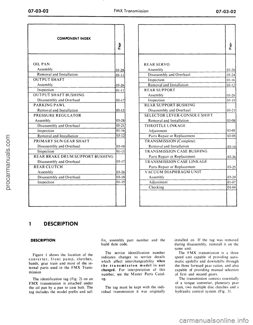
COMPONENT INDEX
OIL PAN
Assembly
Removal and Installation
OUTPUT SHAFT
Assembly
Inspection
OUTPUT SHAFT BUSHING
Disassembly and Overhaul
PARKING PAWL
Removal and Installation
PRESSURE REGULATOR
Assembly
Disassembly and Overhaul
Inspection
Removal and Installation
PRIMARY SUN GEAR SHAFT
Disassembly and Overhaul
Inspection
REAR BRAKE DRUM SUPPORT BUSHING
Disassembly and Overhaul
REAR CLUTCH
Assembly
Disassembly and Overhaul
Inspection
Page
03-29
03-11
03-26
01-11
03-17
03-13
03-28
03-21
01-16
03-12
03-18
01-11
03-17
03-26
03-18
01-15
REAR SERVO
Assembly
Disassembly and Overhaul
Inspection
Removal and Installation
REAR SUPPORT
Assembly
Inspection
REAR SUPPORT BUSHING
Disassembly and Overhaul
SELECTOR LEVER-CONSOLE SHIFT
Removal and Installation
THROTTLE LINKAGE
Adjustment
Parts Repair or Replacement
TRANSMISSION (Complete)
Removal and Installation
TRANSMISSION CASE BUSHING
Parts Repair or Replacement
TRANSMISSION CASE LINKAGE
Parts Repair or Replacement
VACUUM DIAPHRAGM UNIT
Assembly
Adjustment
Checking
Page
03-28
03-24
01-16
03-12
03-28
03-15
03-21
03-08
03-05
03-05
03-14
03-26
03-25
03-29
01-07
01-04
DESCRIPTION
DESCRIPTION
Figure 1 shows the location of the
converter, front pump, clutches,
bands,
gear train and most of the in-
ternal parts used in the FMX Trans-
mission
The identification tag (Fig. 2) on an
FMX transmission is attached under
the oil pan by a pan to case bolt. The
tag includes the model prefix and suf-
fix, assembly part number and the
build date code.
The service identification number
indicates changes to service details
which affect interchangeability when
the transmission model is not
changed. For interpretation of this
number, see the Master Parts Catal-
og-
The tag must be kept with the indi-
vidual transmission it was originally
installed on. If the tag was removed
during disassembly, reinstall it on the
same unit.
The FMX transmission is a three
speed unit capable of providing auto-
matic upshifts and downshifts through
the three forward gear ratios, and also
capable of providing manual selection
of first and second gears.
The transmission consists essentially
of a torque converter, planetary gear
train, two multiple disc clutches and a
hydraulic control system (Fig. 3).
procarmanuals.com
Page 351 of 413

07-03-11
FMX Transmission
07
03-11
GOVERNOR
COMPENSATOR
PRESSURE TUBE
MAIN CONTROL
VALVE TUBE
COUNTERWEIGHT
D 1815-A
FIG. 16—Governor Installed
ber to remove all weight from the
housing.
10.
Loosen the parking brake cable
adjustment nut enough to disconnect
the cables from the equalizer.
11.
Remove the extension housing
attaching bolts. Slide the housing off
the output shaft and remove the gas-
ket. When removing
the
extension
housing and/or governor, hold
the
output shaft
and
rear support from
moving rearward
to
prevent
the
needle
bearing
and
race from dropping
out of
location.
12.
Remove the governor to coun-
terweight attaching screws. Lift the
governor from the counterweight (Fig.
16).
13.
Lubricate the governor valve
parts with clean transmission fluid.
Make certain that
the
valve moves
freely
in the
valve body bore.
14.
Position the governor valve
body on the counterweight with the
cover facing toward the front of the
vehicle. Install and tighten the two at-
taching screws to the specified torque.
15.
Position a new extension hous-
ing gasket on the rear of the transmis-
sion case.
16.
Slide the extension housing into
place and secure it to the transmission
case with the attaching bolts. Torque
the bolts to specification. With the ex-
tension housing installed, rotate
the
output shaft.
The
shaft must rotate
freely
by
hand.
If the
shaft
is
tight
or
bound
up, it is
likely that
the
needle
bearing
and
race have dropped
out of
location,
in
which case,
the
transmis-
sion must
be
partially disassembled
and
the
bearing
and
race repositioned.
17.
Connect the speedometer cable
to the extension housing.
18.
Raise the transmission high
enough with a jack to position the en-
FRONT SERVO
FLUID TUBES
PRESSURE
REGULATOR
D 1817-A
FIG. 17—Typical Hydraulic Control System
gine rear support on the crossmember.
Secure the support to the crossmem-
ber with attaching bolt.
19.
Lower the transmission and re-
move the jack. Secure the extension
housing to the rear support with the
two attaching bolts.
20.
Connect the parking brake
cables to the equalizer and adjust the
cables as required.
21.
Install the driveshaft.
22.
Fill the transmission to the cor-
rect level with the specified fluid.
OIL
PAN AND
CONTROL
VALVE BODY REPLACEMENT
1. Raise the vehicle so that the
transmission fluid pan is accessible.
2.
Drain the fluid from the trans-
mission by loosening the pan attach-
ing bolts starting at the rear of the
pan and working toward the front.
When most of the fluid has drained
from the pan, remove the remainder
of the attaching bolts. Remove the
pan and gasket. Discard the gasket. If
the same fluid is to be used again in
the transmission, filter the fluid
through a 100-mesh screen before in-
stalling it in the transmission. Re-use
the fluid only if it is in good condi-
tion.
3.
Disconnect the hose from the
vacuum diaphragm unit. Remove the
diaphragm unit using tool FCO-24.
Do
not use any
tools
on the dia-
phragm housing, such
as
pliers, pipe
wrenches,
etc. Do not
allow solvents
to enter
the
diaphragm unit. Remove
the push rod. Remove the fluid screen
retaining clip and the screen.
4.
Remove the fluid filter retaining
clip and the filter.
5.
Remove the two tubes which
connect to the pressure regulator and
the control valve body (Fig. 17).
6. Loosen the front servo attaching
bolts three turns.
7.
Remove the three control valve
body attaching bolts, and lower the
valve body while pulling it off the
front servo tubes. Be carefull not to
damage
the
valve body
or the
tubes.
8.
Before installing the control
valve body, check for a bent manual
valve by rolling it on a flat surface.
9. Install the control valve body by
aligning the front servo tubes with the
holes in the valve body. Shift the man-
ual lever to the 1 detent, and place the
inner downshift lever between the
downshift lever stop and the downshift
valve.
The
manual valve must engage
the actuating
pin in the
manual detent
lever.
10.
Install but do not tighten, the
control valve body attaching bolts.procarmanuals.com
Page 353 of 413
07-03-13
FMX Transmission
07-03-13
EXTENSION HOUSING
BUSHING AND REAR SEAL
REPLACEMENT
1.
Disconnect the drive shaft from
the transmission.
2.
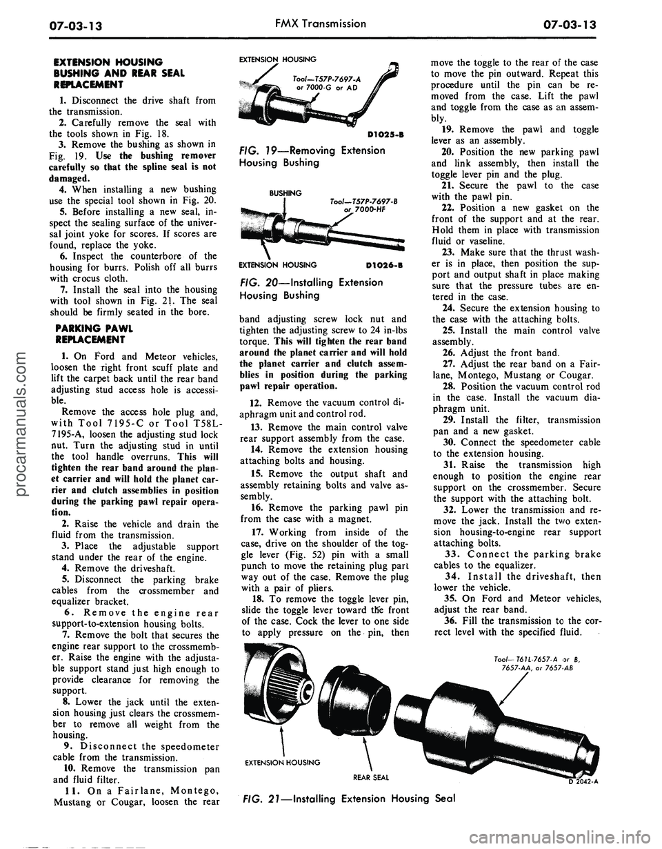
Carefully remove the seal with
the tools shown in Fig. 18.
3.
Remove the bushing as shown in
Fig. 19. Use the bushing remover
carefully so that the spline seal is not
damaged.
4.
When installing a new bushing
use the special tool shown in Fig. 20.
5.
Before installing a new seal, in-
spect the sealing surface of the univer-
sal joint yoke for scores. If scores are
found, replace the yoke.
6. Inspect the counterbore of the
housing for burrs. Polish off all burrs
with crocus cloth.
7.
Install the seal into the housing
with tool shown in Fig. 21. The seal
should be firmly seated in the bore.
PARKING PAWL
REPLACEMENT
1.
On Ford and Meteor vehicles,
loosen the right front scuff plate and
lift the carpet back until the rear band
adjusting stud access hole is accessi-
ble.
Remove the access hole plug and,
with Tool 7195-C or Tool T58L-
7195-A, loosen the adjusting stud lock
nut. Turn the adjusting stud in until
the tool handle overruns. This will
tighten the rear band around the plan-
et carrier and will hold the planet car-
rier and clutch assemblies in position
during the parking pawl repair opera-
tion.
2.
Raise the vehicle and drain the
fluid from the transmission.
3.
Place the adjustable support
stand under the rear of the engine.
4.
Remove the driveshaft.
5.
Disconnect the parking brake
cables from the crossmember and
equalizer bracket.
6. Remove the engine rear
support-to-extension housing bolts.
7.
Remove the bolt that secures the
engine rear support to the crossmemb-
er. Raise the engine with the adjusta-
ble support stand just high enough to
provide clearance for removing the
support.
8. Lower the jack until the exten-
sion housing just clears the crossmem-
ber to remove all weight from the
housing.
9. Disconnect the speedometer
cable from the transmission.
10.
Remove the transmission pan
and fluid filter.
11.
On a Fairlane, Montego,
Mustang or Cougar, loosen the rear
EXTENSION HOUSING
Tool-T57P-7697-A
or 7000-G or AD
D1O25-B
FIG. 79—Removing Extension
Housing Bushing
BUSHING
Tool—T57P-7697-B
7000-HF
EXTENSION HOUSING
D1O26-B
FIG. 20—Installing Extension
Housing Bushing
band adjusting screw lock nut and
tighten the adjusting screw to 24 in-lbs
torque. This will tighten the rear band
around the planet carrier and will hold
the planet carrier and clutch assem-
blies in position during the parking
pawl repair operation.
12.
Remove the vacuum control di-
aphragm unit and control rod.
13.
Remove the main control valve
rear support assembly from the case.
14.
Remove the extension housing
attaching bolts and housing.
15.
Remove the output shaft and
assembly retaining bolts and valve as-
sembly.
16.
Remove the parking pawl pin
from the case with a magnet.
17.
Working from inside of the
case,
drive on the shoulder of the tog-
gle lever (Fig. 52) pin with a small
punch to move the retaining plug part
way out of the case. Remove the plug
with a pair of pliers.
18.
To remove the toggle lever pin,
slide the toggle lever toward tlfe front
of the case. Cock the lever to one side
to apply pressure on the pin, then
move the toggle to the rear of the case
to move the pin outward. Repeat this
procedure until the pin can be re-
moved from the case. Lift the pawl
and toggle from the case as an assem-
bly.
19.
Remove the pawl and toggle
lever as an assembly.
20.
Position the new parking pawl
and link assembly, then install the
toggle lever pin and the plug.
21.
Secure the pawl to the case
with the pawl pin.
22.
Position a new gasket on the
front of the support and at the rear.
Hold them in place with transmission
fluid or vaseline.
23.
Make sure that the thrust wash-
er is in place, then position the sup-
port and output shaft in place making
sure that the pressure tubes are en-
tered in the case.
24.
Secure the extension housing to
the case with the attaching bolts.
25.
Install the main control valve
assembly.
26.
Adjust the front band.
27.
Adjust the rear band on a Fair-
lane,
Montego, Mustang or Cougar.
28.
Position the vacuum control rod
in the case. Install the vacuum dia-
phragm unit.
29.
Install the filter, transmission
pan and a new gasket.
30.
Connect the speedometer cable
to the extension housing.
31.
Raise the transmission high
enough to position the engine rear
support on the crossmember. Secure
the support with the attaching bolt.
32.
Lower the transmission and re-
move the jack. Install the two exten-
sion housing-to-engine rear support
attaching bolts.
33.
Connect the parking brake
cables to the equalizer.
34.
Install the driveshaft, then
lower the vehicle.
35.
On Ford and Meteor vehicles,
adjust the rear band.
36.
Fill the transmission to the cor-
rect level with the specified fluid.
Too/—
T6U-7657-A or 8,
7657-AA, or 7657 AB
EXTENSION HOUSING
REAR SEAL
FIG. 21—Installing Extension Housing Sealprocarmanuals.com
Page 380 of 413

07-04-11
C-6 Automatic Transmission
07-04-11
BAND ADJUSTMENT
INTERMEDIATE BAND
1.
Raise the vehicle on a hoist or
jack stands.
2.
Clean all the dirt from the band
adjusting screw area. Remove and dis-
card the lock nut.
3.
Install a new lock nut and tight-
en the adjusting screw to 10 ft-lbs tor-
que (Fig. 15).
4.
Back off the adjusting screw ex-
actly 1 full turn.
5.
Hold the adjusting screw from
turning and torque the lock nut to
specification.
6. Lower the vehicle.
EXTENSION HOUSING OR
GOVERNOR REPLACEMENT
REMOVAL
1.
Raise the vehicle on a hoist or
stands.
2.
Disconnect the parking brake
cable from the equalizer. On a Lin-
coln Continental, remove the equaliz-
er.
3.
Disconnect the driveshaft from
the rear axle flange and remove it
from the transmission.
4.
Disconnect the speedometer
cable from the extension housing.
5.
Remove the engine rear
support-to-extension housing attaching
bolts.
On a Lincoln Continental, remove
the reinforcement plate from under
the transmission oil pan.
6. Place a jack under the transmis-
sion and raise it just enough to re-
move the weight from the engine rear
support.
7.
Remove the bolt that secures the
engine rear support to the crossmemb-
er and remove the support.
8. Place a drain pan under the rear
of the transmission case.
9. Lower the transmission and re-
move the extension housing attaching
bolts.
Slide the extension housing off
the output shaft and allow the fluid to
drain.
10.
Remove the governor attaching
bolts (Fig. 16) and remove the gover-
nor from the flange.
INSTALLATION
1.
Secure the governor (Fig. 16) to
the distributor flange with the attach-
ing bolts. Torque the bolts to specifi-
cation.
TOOL-T59 P-77370-B
FIG. 75—Adjusting Band
D 1597-A
TUBES
DISTRIBUTOR
GOVERNOR
SPACER
D1598-A
FIG. 76—Governor Installed
2.
Clean the mounting surface on
the transmission and on the extension
housing. Position a new gasket on the
transmission.
3.
Hold the extension housing in
place and secure it with the attaching
bolts.
4.
Raise the transmission high
enough to position the engine rear
support on the crossmember.
5.
Secure the support to the cross
member with the attaching bolt and
nut. Torque the bolt to specification.
6. Lower the transmission and re-
move the jack. Install and torque the
engine rear support-to-extension hous-
ing attaching bolts to specification.
On a Lincoln Continental, install
the reinforcement plate and secure it
with the attaching bolts.
7.
Secure the speedometer cable to
the extension housing with the attach-
ing bolt.
8. Connect the parking brake cable
to the equalizer. On a Lincoln Conti-
nental, connect the parking brake
equalizer. Adjust the parking brake as
required.
9. Install the drive shaft.
10.
Fill the transmission to the cor-
rect level with the specified fluid.
SERVO REPLACEMENT
ALL VEHICLES EXCEPT
LINCOLN CONTINENTAL
Removal
1.
Raise the vehicle on a hoist or
stands.
2.
Remove the engine rear
support-to-extension housing attaching
bolts.
3.
Raise the transmission high
enough to remove the weight from the
engine rear support.
4.
Remove the bolt that secures the
engine rear support to the crossmemb-
er. Remove the support.
5.
Lower the transmission and re-
move the jack.
6. Place a drain pan beneath the
servo.
Remove the bolts that attach
the servo cover to the transmission
case.
7.
Remove the cover, piston, spring
and gasket from the case, screwing the
band adjusting screw inwards as the
piston is removed. This insures that
there will be enough tension on the
band to keep the struts properly en-
gaged in the band end notches while
the piston is removed.
SEAL REPLACEMENT
1.
Apply air pressure to the port in
the servo cover to remove the piston
and rod.
2.
Remove the seals from the piston
(Fig. 17).
On a Continental Mark III, replace
the complete piston and rod assembly
if the piston or piston sealing lips are
unserviceable or damaged.
3.
Remove the seal from the cover.
4.
Dip the new seals in transmission
fluid.
5.
Install the new seals on the pis-
ton and cover.
6. Coat two new gaskets with pe-
troleum jelly and install the gaskets
on the cover.
7.
Dip the piston in transmission
fluid and install it in the cover.procarmanuals.com