1969 FORD MUSTANG section 18
[x] Cancel search: section 18Page 112 of 413

03-04-03
Automatic Air Leveling System — Lincoln Continental
03-04-03
outlet lines to their respective parts.
3.
Adjust the trim height as de-
tailed in Section 4.
4.
Connect the link to the arm.
5.
Remove the jack stands and
lower the vehicle.
SUPER LIFT SHOCK ABSORBER
REMOVAL
1.
Raise the vehicle and place jack
stands under the axle to compress the
super lift.
2.
Loosen the air line or lines (right
super lift) slowly to release the air
from the system. Then, disconnect the
line or lines.
3.
Remove the three mounting plate
attaching screws from the upper end
of the super lift.
4.
Remove the attaching nut and
washer from the lower end of the
super lift and remove it from the vehi-
cle.
5.
Remove the nut, outer washer
and the insulator that attach the super
lift to the mounting plate. Remove the
plate, remaining insulator and washer.
INSTALLATION
1.
Position a washer, insulator,
mounting plate, insulator, washer and
nut on the stud at the upper end of
the super lift. Torque the nut to speci-
fication.
2.
Install the mounting plate, outer
insulator, washer and nut on the stud.
Torque the nut to specification.
3.
Attach the mounting plate and
shock absorber to the crossmember
with the attaching screws to specifica-
tions.
4.
Connect the lower end of the
super lift to the mounting stud with
the washers and attaching nut. Torque
the nut to specification.
5.
Connect the air line or lines
(right super lift) to the super lift.
6. Start the engine and check for
leaks.
3 IN-VEHICLE ADJUSTMENTS AND REPAIRS
REGULATOR ADJUSTMENT HEIGHT CONTROL VALVE
The regulator may be adjusted if
the regulator pressure is under 100 psi
with the reservoir pressure at a mini-
mum of 140 psi. If the regulated pres-
sure exceeds 130 psi, the regulator
must be replaced.
To adjust the regulator, remove the
boot and reposition the sleeve and re-
tainer deeper into the body of the re-
gulator, using a deep well socket (Fig.
4).
If the regulator pressure remains
under 100 psi, replace regulator.
SILICONE FLUID
REPLACEMENT
If the height control valve time
delay does not fall within specifica-
tion, the silicone fluid must be re-
placed. Then repeat the time delay
test. If delay is still not within specifi-
cations, replace the height control
valve.
1.
Remove control valve and clean
the exterior of the valve thoroughly.
2.
Position the valve with delay
plug on top. Remove delay plug and
drain silicone fluid from the chamber.
Remove the O-ring from the chamber
(Fig. 5), and discard the O-ring.
3.
Remove the cover plate retaining
ring, using snap ring pliers. Remove
the delay cover from the valve body.
Remove the O-ring from the chamber,
and discard the O-ring.
4.
Place a new O-ring over the
delay plug and install the plug. Tor-
que the plug to 20-30 in-lbs. .
5.
Pour silicone fluid into the delay
piston chamber until fluid level is 5/16
inch below the top edge of the body.
Add or remove fluid with an eye drop-
per until the proper fluid level is
reached.
6. Hold the control valve body in a
vise with the delay chamber elevated
slightly. Carefully operate the lever to
purge trapped air from the fluid.
7.
Place a new O-ring in the groove
around the delay piston bore. Install
5/16" TO
FLUID LEVEL
F 1405 A
FIG. 4—Adjusting Regulator
F1406 A
FIG. 5—Replacing Silicone Fluidprocarmanuals.com
Page 133 of 413
03-05-20
Steering Columns And Linkage
03-05-20
placed if it becomes worn or damaged
(Figs.
18 through 21). Do not attempt
to straighten the sleeve if damaged.
1.
Remove the spindle connecting
rod end assemblies as described in the
previous sub-section.
2.
Screw the spindle rod end assem-
blies into the new sleeve the same
number of turns as the ends that were
removed. Do not tighten the clamp
bolts at this time.
3.
Position the sleeve and end as-
sembly on the center link and the
spindle arm. Install the attaching nut,
torque it to specification, and install
the cotter pin.
4.
Check and, if necessary, adjust
toe-in (Part 3-1). After toe-in is
checked and adjusted, oil the sleeve
clamp bolts then torque them to speci-
fication. The sleeve clamp must be in-
stalled as shown in Figs. 18 through
21.
CENTER LINK
REPLACEMENT
The center link connecting the Pit-
man arm and the idler arm is non-
adjustable and is provided with ta-
pered holes to accommodate the ball
studs (Figs. 18 through 21). The link
should be replaced when damaged or
when worn at the ball studs. On Lin-
coln Continental models, the link
should be replaced if excessive loose-
ness is noticed in either ball stud sock-
et.
REMOVAL
1.
Raise the vehicle on a hoist and
position safety stands.
2.
Remove the cotter pins and nuts
that attach both inner connecting rod
ends to the center link (Figs. 18
through 21).
3.
Disconnect the inner connecting
rod ends from the center link using
Tool 3290-C (Fig. 22).
4.
Remove the cotter pin and nut
attaching the idler arm to the center
link. Disconnect the idler arm from
the center link using Tool 3290-C for
Lincoln Continental models only.
5.
Remove the cotter pin and nut
attaching the Pitman arm to the cen-
ter link. Disconnect the Pitman arm
from the center link (use Tool 3290-C)
and remove the center link. On ve-
hicles equipped with the non-integral
power steering system, remove the
center link from the control valve as
detailed in Part 3-7.
INSTALLATION
1.
Replace the rubber seals on the
spindle connecting rod ends, if re-
quired.
2.
Position the center link to the
Pitman arm and idler arm and install
the attaching nuts loosely. On all ve-
hicles except Lincoln Continental
models, place the idler arm and the
front wheels in the straight ahead po-
sition to insure keeping the steering
wheel aligned and to prevent bushing
damage after the attaching nuts have
been torqued. On Lincoln Continental
models, insure that the seal is properly
installed on the center link. Torque
the nuts to the low end of the specifi-
cation. Continue to tighten each nut
until the slots in the nut align with the
hole in the stud. Then install a new
cotter pin.
3.
Position the spindle connecting
rod ends to the center link and install
the attaching nuts. Torque the nuts to
the low end of the specification. Con-
tinue to tighten each nut until the
slots in the nut align with the hole in
the stud. Then, install a new cotter
pin.
4.
Remove the safety stands, lower
the vehicle, check and adjust toe-in to
specification (Part 3-1).
STEERING IDLER ARM
AND BRACKET ASSEMBLY
REPLACEMENT
REMOVAL
If the idler arm bushings are worn
the complete idler arm assembly must
be replaced. In Lincoln Continental
models, if the socket at the idler
bracket is excessively loose, replace
the complet assembly.
1.
Remove the cotter pin and nut
attaching the steering center link at
the idler arm (Figs. 18 through 21).
2.
Disconnect the center link from
the idler arm (on Lincoln Continental
models, use Tool 3290-C).
3.
Remove the two bolts that attach
the idler arm and bracket assembly to
the frame.
INSTALLATION
1.
Secure the new idler arm and
bracket assembly to the frame with
the two attaching bolts (nuts and flat
washers as shown in Figs. 18, 19 and
21).
2.
On all vehicles except Lincoln
Continental models, place the idler
arm and the front wheels in the
straight ahead position to insure keep-
ing the steering wheel aligned and to
prevent bushing damage after the at-
taching nut has been torqued. Insert
the center link stud through the hole
in the end of the idler arm and install
the nut and washer.
On Lincoln Continental models, in-
sert the center link stud through the
hole in the end of the idler arm insur-
ing that the seal is properly installed
on the center link.
3.
Torque the idler arm rod nut to
specification and install a new cotter
pin.
PITMAN ARM
REPLACEMENT
REMOVAL
1.
Remove the cotter pin from the
castellated nut that attaches the steer-
ing center link to the Pitman arm.
Remove the castellated nut.
2.
Disconnect the steering center
link from the Pitman arm with tool
3290-C.
3.
Remove the Pitman arm attaching
nut and lock washer.
4.
Position the front wheels in the
straight ahead position. Remove the
Pitman arm with tool T64P-3590-F
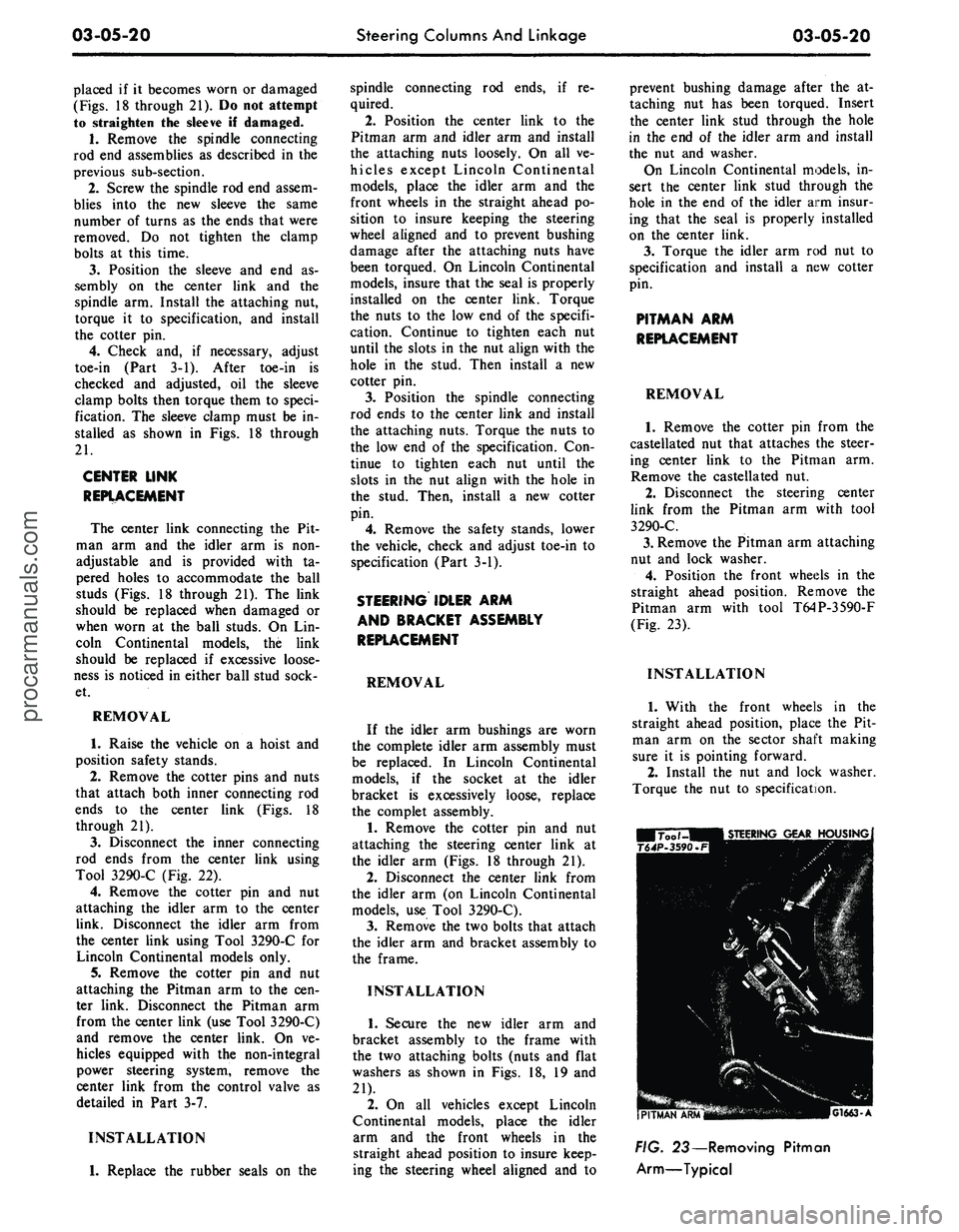
(Fig. 23).
INSTALLATION
1.
With the front wheels in the
straight ahead position, place the Pit-
man arm on the sector shaft making
sure it is pointing forward.
2.
Install the nut and lock washer.
Torque the nut to specification.
G1663-A
FIG. 23— Removing Pitman
Arm—Typicalprocarmanuals.com
Page 141 of 413
03-07-03
Ford Design Non-Integral Power Steering System
03-07-03
5.
Lower the vehicle and disconnect
the fluid return hose from the reser-
voir.
6. Disconnect the fluid pressure
hose from the pump outlet fitting.
7.
Remove 1 bolt attaching the
hoses,
insulator, and the retainer to
the frame side rail and remove the
hoses,
and the insulator and retainer
as an assembly from the vehicle.
8. Remove the pressure and return
hoses from the retainer and insulator.
INSTALLATION
1.
Install the pressure and return
hoses in the insulator and retainer.
Paint stripe on pressure hose must be
aligned with slot in insulator. Paint or
tape band on return hose must be cen-
tered in insulator. Position the assem-
bly to the frame side rail and install
the attaching bolt.
2.
Place a hose clamp on the fluid
return hose and install the hose on the
power steering pump reservoir return
fitting.
3.
Torque the pump outlet fitting to
specification (Part 3-13). Then, con-
nect the pressure hose to the outlet fit-
ting and torque the fitting to specifica-
tion.
4.
Raise the vehicle and connect the
pressure and return lines to the con-
trol valve.
5.
Install the clamp to retain the
hose tubes to the control valve.
6. Lower the vehicle and fill the
power steering pump reservoir with
fluid, C1AZ-19582-A, to the proper
level (Part 3-1).
7.
Start the engine and turn the
steering wheel to each end of its travel
several times to cycle the system.
Then, check for fluid leaks.
8. Stop the engine and again check
the power steering fluid level (Part
3-1). Add fluid as required.
REMOVAL AND INSTALLATION
HOISTING INSTRUCTIONS
Damage to suspension and/or steer-
ing linkage components may occur if
care is not exercised when positioning
the hoist adapters of 2 post hoists
prior to lifting the vehicle.
If a 2 post hoist is used to lift the
vehicle, place the adapters under the
front suspension lower arms. Do not
allow the adapters to contact the
steering linkage.
STEERING GEAR
Refer to Group 3-6, Section 3 for
detailed instructions.
POWER STEERING PUMP
Refer to Group 3-10, Section 3 for
detailed instructions.
POWER STEERING CONTROL
VALVE
REMOVAL
1.
Disconnect the 4 fluid line fit-
tings at the control valve, and drain
the fluid from the lines. Turn the front
wheels to the left and right several
times to force all the fluid from the
system.
2.
Loosen the clamping nut and
bolt at the right end of the sleeve.
3.
Remove the roll pin from the
steering arm-to-idler arm rod -through
the slot in the sleeve.
4.
Remove the control valve ball
stud nut.
5.
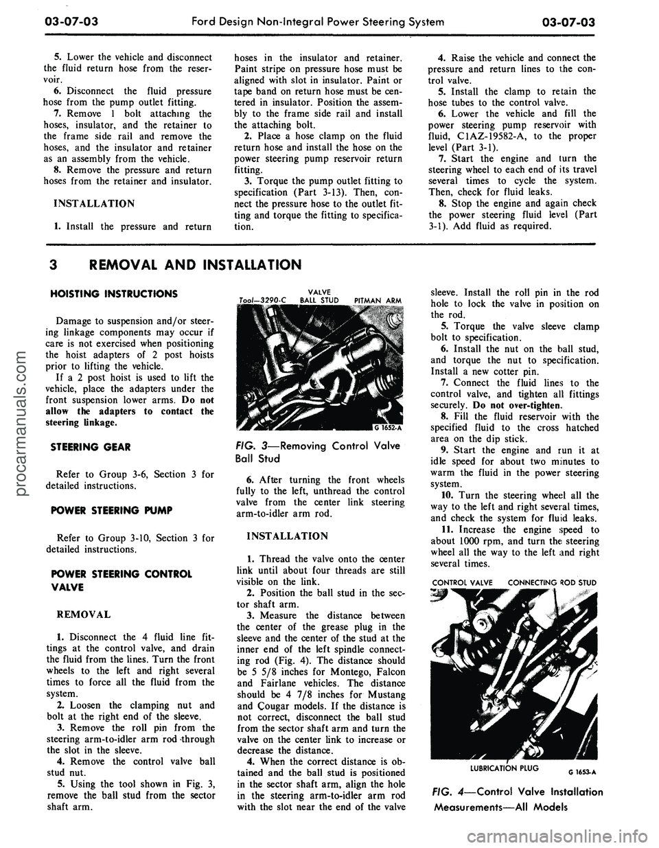
Using the tool shown in Fig. 3,
remove the ball stud from the sector
shaft arm.
VALVE
Too/-3290-C BALL STUD PITMAN ARM
FIG. 3—Removing Control Valve
Ball Stud
6. After turning the front wheels
fully to the left, unthread the control
valve from the center link steering
arm-to-idler arm rod.
INSTALLATION
1.
Thread the valve onto the center
link until about four threads are still
visible on the link.
2.
Position the ball stud in the sec-
tor shaft arm.
3.
Measure the distance between
the center of the grease plug in the
sleeve and the center of the stud at the
inner end of the left spindle connect-
ing rod (Fig. 4). The distance should
be 5 5/8 inches for Montego, Falcon
and Fairlane vehicles. The distance
should be 4 7/8 inches for Mustang
and Cougar models. If the distance is
not correct, disconnect the ball stud
from the sector shaft arm and turn the
valve on the center link to increase or
decrease the distance.
4.
When the correct distance is ob-
tained and the ball stud is positioned
in the sector shaft arm, align the hole
in the steering arm-to-idler arm rod
with the slot near the end of the valve
sleeve. Install the roll pin in the rod
hole to lock the valve in position on
the rod.
5.
Torque the valve sleeve clamp
bolt to specification.
6. Install the nut on the ball stud,
and torque the nut to specification.
Install a new cotter pin.
7.
Connect the fluid lines to the
control valve, and tighten all fittings
securely. Do not over-tighten.
8. Fill the fluid reservoir with the
specified fluid to the cross hatched
area on the dip stick.
9. Start the engine and run it at
idle speed for about two minutes to
warm the fluid in the power steering
system.
10.
Turn the steering wheel all the
way to the left and right several times,
and check the system for fluid leaks.
11.
Increase the engine speed to
about 1000 rpm, and turn the steering
wheel all the way to the left and right
several times.
CONTROL VALVE CONNECTING ROD STUD
LUBRICATION PLUG
G1653-A
FIG. 4—Control Valve Installation
Measurements—All Modelsprocarmanuals.com
Page 144 of 413
03-07-06
Ford Design Non-Integral Power Steering System
03-07-06
VALVE HOUSING
VALVE SPOOL
G
1659-
A
FIG. 70—Inserting Valve Spool
13.
Pick up the housing, and slide
the spool back and forth in the hous-
ing to check for free movement.
14.
Place the valve sleeve on the
housing so that the ball stud is on the
same side of the housing as the ports
for the two power cylinder lines. In-
stall the two bolts in the sleeve, and
torque them to specifications.
15.
Place the adapter on the cen-
tering spring end of the housing, and
install the bushing, washers, spacers,
and centering spring on the valve
spool bolt.
16.
Compress the centering spring,
and install the nut on the bolt. Tight-
en the nut snug (90-100 in-lbs); then
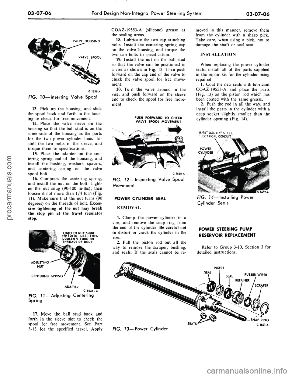
loosen it not more than 1/4 turn (Fig.
11).
Make sure that the nut turns (90
degrees) on the threads of bolt. Exces-
sive tightening of the nut may break
the stop pin at the travel regulator
stop.
TIGHTEN NUT SNUG
(90-100 IN -LBS) THEN
LOOSEN % TURN ON
THREADS OF BOLT
ADJUSTING
NUT
CENTERING SPRING
ADAPTER
G 1034 -C
FIG. 11—Adjusting Centering
Spring
17.
Move the ball stud back and
forth in the sleeve slot to check the
spool for free movement. See Part
3-13 for the specified travel. Apply
COAZ-19553-A (silicone) grease at
the sealing areas.
18.
Lubricate the two cap attaching
bolts.
Install the centering spring cap
on the valve housing, and torque the
two cap bolts to specification.
19.
Install the nut on the ball stud
so that the valve can be positioned in
a vise as shown in Fig. 12. Then push
forward on the cap end of the valve to
check the valve spool for free move-
ment.
20.
Turn the valve around in the
vise,
and push forward on the sleeve
end to check the spool for free move-
ment.
PUSH FORWARD TO CHECK
VALVE SPOOL MOVEMENT
G 1660-A
FIG. 12—Inspecting Valve Spool
Movement
POWER CYLINDER SEAL
REMOVAL
1.
Clamp the power cylinder in a
vise,
and remove the snap ring from
the end of the cylinder. Be careful not
to distort or crack the cylinder in the
vise.
2.
Pull the piston rod out all the
way to remove the scraper, bushing,
and seals. If the seals cannot be re-
moved in this manner, remove them
from the cylinder with a sharp pick.
Take care, when using a pick, not to
damage the shaft or seal seat.
INSTALLATION
When replacing the power cylinder
seals,
install all of the parts supplied
in the repair kit for the cylinder being
repaired.
1.
Coat the new seals with lubricant
COAZ-19553-A and place the parts
(Fig. 13) on the piston rod which has
been coated with the same grease.
2.
Push the rod in all the way, and
install the parts in the cylinder with a
deep socket slightly smaller than the
cylinder opening (Fig. 14).
15/16"
O.D. X6" STEEL
ELECTRICAL CONDUIT
POWER
CYLINDER
G 1662-A
FIG. 14—Installing Power
Cylinder Seals
POWER STEERING PUMP
RESERVOIR REPLACEMENT
Refer to Group 3-10, Section 3 for
detailed instructions.
INSERT
RUBBER WIPER
SCRAPER
SEATS'
FIG. 73—Power Cylinder
SNAP RING
G 1661-Aprocarmanuals.com
Page 154 of 413
03-09-02
Saginaw Design Integral Power Steering Gear
03-09-02
WORM
ADJUSTER PLUG
TORSION BAR
STUB SHAFT
SEAL
NEEDLE BEARINGS
TEFLON RING
TEFLON SEALS
SECTOR SHAFT
FIG.l —
Power
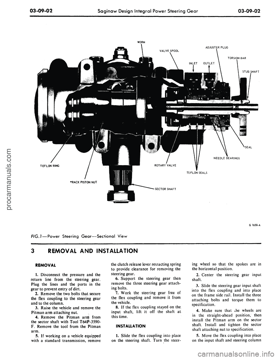
Steering Gear—Sectional View
G 1650-A
REMOVAL
AND
INSTALLATION
REMOVAL
1.
Disconnect
the
pressure
and the
return line from
the
steering gear.
Plug
the
lines
and the
ports
in the
gear to prevent entry of dirt.
2.
Remove the two bolts that secure
the flex coupling
to the
steering gear
and
to
the column.
3.
Raise
the
vehicle
and
remove
the
Pitman arm attaching nut.
4.
Remove
the
Pitman arni from
the sector shaft with Tool T64P-3590-
F.
Remove
the
tool from
the
Pitman
arm.
5.
If
working
on a
vehicle equipped
with
a
standard transmission, remove
the clutch release lever retracting spring
to provide clearance
for
removing
the
steering gear.
6. Support
the
steering gear then
remove
the
three steering gear attach-
ing bolts.
7.
Work
the
steering gear free
of
the flex coupling
and
remove
it
from
the vehicle.
8.
If
the flex coupling stayed
on the
input shaft, lift
it off the
shaft
at
this time.
INSTALLATION
1.
Slide
the
flex coupling into place
on
the
steering shaft. Turn
the
steer-
ing wheel
so
that
the
spokes
are in
the horizontal position.
2.
Center
the
steering gear input
shaft.
3.
Slide the steering gear input shaft
into
the
flex coupling
and
into place
on
the
frame side rail. Install the three
attaching bolts
and
torque them
to
specification.
4.
Make sure that
ihe
wheels
are
in
the
straight-ahead position, then
install
the
Pitman
arm on the
sector
shaft. Install
and
tighten
the
sector
shaft attaching nut to specification.
5.
Move the flex coupling into place
on
the
input shaft
and
steering columnprocarmanuals.com
Page 162 of 413

03-10-01
Ford-Thompson Power Steering Pump*
03-10-01
PART 3-10 Ford-Thompsonr Power Steering Pump
COMPONENT INDEX
PUMP BELT TENSION ADJUSTMENT
PUMP DRIVE BELT
Removal and Installation
POWER STEERING PUMP
Cleaning and Inspection (See Part 03-01)
Description
Disassembly and Assembly
Removal and Installation
POWER STEERING PUMP PULLEY
Removal and Installation
POWER STEERING PUMP RESERVOIR
Removal and Installation
ROTOR SHAFT SEAL
Removal and Installation
MODEL APPLICATION
All
Models
Ford
10-01
l5-O2
10-01
10-04
10-02
10-03
10-03
10-04
Mercury
10-01
10-02
10-01
10-04
10-02
10-03
10-03
10-04
Meteor
10-01
10-02
10-01
10-04
10-02
10-03
10-03
10-04
Cougar
10-01
10-02
10-01
10-04
10-02
10-03
10-03
10-04
Fairlane
10-01
10-02
10-01
10-04
10-02
10-03
10-03
10-04
Falcon
10-01
10-02
10-01
10-04
10-02
10-03
10-03
10-04
Montego
10-01
10-02
10-01
10-04
10-02
10-03
10-03
10-04
Mustang
10-01
10-02
10-01
10-04
10-02
10-03
10-03
10-04
Lincoln-
Continental
N/A
N/A
N/A
N/A
N/A
N/A
N/A
N/A
Thunderbird
10-01
10-02
10-01
10-04
10-02
10-03
10-03
10-04
Continental-
Mark
III
N/A
N/A
N/A
N/A
N/A
N/A
N/A
'N/A
A page number indicates that the item is for the vehicle listed at the head of the column.
N/A indicates that the item is not applicable to the vehicle listed.
1
DESCRIPTION
The Ford-Thompson power steering
pump is a belt driven slipper type
pump which is integral with the reser-
voir (Fig. 1). It is constructed so that
the reservoir is attached to the rear
side of the pump housing front plate
and the pump body is encased within
the reservoir (Fig. 2).
IN-VEHICLE ADJUSTMENTS AND REPAIRS
PUMP BELT TENSION
ADJUSTMENT
Pump drive belt tension cannot be
checked accurately using the
•
thumb
pressure or belt deflection methods.
Correct belt adjustment is assured
only with the use of a belt tension
gauge.
1.
Check the belt tension with a
belt tension gauge tool T63L-8620-A.
With a new belt, or one that has been
run for less than 15 minutes, the ten-
sion should be within 120-150 lbs.
With a belt that has been run for
more than 15 minutes, the tension
should be within 90-120 lbs.
2.
To adjust the belt, loosen the
mounting bolts incorporated on the
front face of the pump cover plate
(hub side) and one nut at the rear of
the reservoir. Fix a 9/16 inch open
end wrench on the nrojecting 1/2 inch
boss on the cover -'plate a"hd pry up-
ward to correct tension on 6 cyl. en-
gines.
DIPSTICK.
DRIVE
PULLEY
RELIEF VALVE
RESERVOIR
ORIFICE PLUG
G1479-B
FIG.
1—Power
Steering Pump—Sectional View
procarmanuals.com
Page 163 of 413

03-10-02
Ford-Thompson Power Steering Pump
03-10-02
LOWER PRESSURE
PLATE 3D590
SPRING-3D601
UPPER PRESSURE
PLATE -3A645
RETAINER END
PLATE-3D589
CAM AND ROTOR
ASSEMBLY-
-3D607
SCREW AND WASHER
ASSEMBLY-379376-S
PULLEY-3D673
PUMP SHAFT
SEAL 3B592
PLATE AND BUSHING
ASSEMBLY-3D643
0-RING
382744-S
HOUSING GASKET
3A760
G1343-B
FIG. 2—Power Steering Pump Disassembled
To adjust the belt on 8 cyl. engines
loosen the mounting bolt in the ad-
justing slot and the nut directly above
the adjusting slot. Place a suitable pry
bar between the cast boss on the
pump mounting bracket and the cast
boss on the pump cover plate and pry
upward to correct tension.
Do not pry against the reservoir to
obtain proper belt load as it can be
deformed and cause a leak.
3.
Recheck the belt tension. When
the tension has been correctly adjusted,
tighten the bolts and the fiut to speci-
fication (Part 3-13).
POWER STEERING
PUMP DRIVE BELT
REPLACEMENT
1.
Loosen the idler pulley attaching
bolts and remove the compressor drive
belt if equipped with an air condition-
er.
2.
Loosen 3 bolts and one nut at-
taching the power steering pump to
the pump bracket, and remove the
pump drive belt.
3.
Position the power steering
pump drive belt on the pulleys.
4.
Adjust the drive belt tension as
outlined in Section 2 to specification
(Part 3-13) and tighten the pump at-
taching bolts and one nut to specifica-
tion.
5.
Install the compressor drive belt
if equipped with an air conditioner
and adjust to specification (Part 16).
REMOVAL AND INSTALLATION
POWER STEERING
PUMP REPLACEMENT
EIGHT CYLINDER
WITHOUT AIR
CONDITIONER AND
ALL SIX CYLINDER
1.
Remove the power steering fluid
from the pump reservoir by discon-
necting the fluid return hose at the
reservoir, and allow the fluid to drain
into a suitable container.
2.
Disconnect the pressure hose
from the pump.
3.
Remove 3 bolts from the front of
the pump and the one nut at the rear
(rear nut on 8 cyl. engines only) that
attach the pump to the mounting
bracket; disconnect the belt from the
pulley and remove the pump from the
vehicle.
4.
Position the pump to the mount-
ing bracket and install the 3 bolts at
the front of pump and (rear nut on 8
cyl.
engines only) the 1 nut at the
rear. Torque to specification.
5.
Place the belt on the pulley and
adjust the belt tension (Section 2) with
Tool T63L-8620-A and tighten the
bolts and nut to specifications.
6. Torque the pressure hose fitting
hex nut to specification. Then, connect
the pressure hose to the fitting and
torque the hose nut to specification.
7.
Connect the hose to the pump.
Then, tighten the clamp.
8. Fill the power steering pump res-
ervoir with transmission fluid C1AZ-
19582-A and cycle the system to re-
move air from the steering gear sys-
tem.
9. Check for leaks and again check
the fluid level. Add fluid as necessary.procarmanuals.com
Page 164 of 413
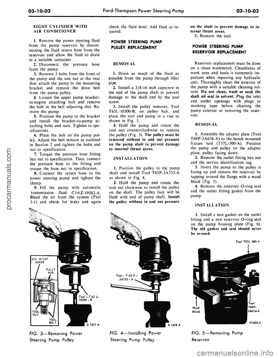
03-10-03
Ford-Thompson Power Steering Pump
03-10-03
EIGHT CYLINDER WITH
AIR CONDITIONER
1.
Remove the power steering fluid
from the pump reservoir by discon-
necting the fluid return hose from the
reservoir and allow the fluid to drain
in a suitable container.
2.
Disconnect the pressure hose
from the pump.
3.
Remove 3 bolts from the front of
the pump and the one nut at the rear
that attach the pump to the mounting
bracket and remove the drive belt
from the pump pulley.
4.
Loosen the upper pump bracket-
to-engine attaching bolt and remove
the bolt in the belt adjusting slot. Re-
move the pump.
5.
Position the pump to the bracket
and install the bracket-to-pump at-
taching bolts and nuts. Tighten to spe-
cifications.
6. Place the belt on the pump pul-
ley. Adjust the belt tension as outlined
in Section 2 and tighten the bolts and
nut to specification.
7.
Torque the pressure hose fitting
hex nut to specification. Then, connect
the pressure hose to the fitting and
torque the hose nut to specification.
8. Connect the return hose to the
power steering pump and tighten the
clamp.
9. Fill the pump with automatic
transmission fluid C1AZ-19582-A.
Bleed the air from the system (Part
3-1) and check for leaks and again
check the fluid level. Add fluid as re-
quired.
POWER STEERING PUMP
PULLEY REPLACEMENT
REMOVAL
1.
Drain as much of the fluid as
possible from the pump through filler
pipe.
2.
Install a 3/8-16 inch capscrew in
the end of the pump shaft to prevent
damage to the shaft end by the tool
screw.
3.
Install the pulley remover, Tool
T63L-1O3OO-B, on pulley hub, and
place the tool and pump in a vise as
shown in Fig. 3.
4.
Hold the pump and rotate the
tool nut counterclockwise to remove
the pulley (Fig. 3). The pulley must be
removed without in and out pressure
on the pump shaft to prevent damage
to internal thrust areas.
INSTALLATION
1.
Position the pulley to the pump
shaft and install Tool T65P-3A733-A
as shown in Fig. 4.
2.
Hold the pump and rotate the
tool nut clockwise to install the pulley
on the shaft. The pulley face will be
flush with end of pump shaft. Install
the pulley without in and out pressure
on the shaft to prevent damage to in-
ternal thrust areas.
3.
Remove the tool.
POWER STEERING PUMP
RESERVOIR REPLACEMENT
Reservoir replacement must be done
on a clean workbench. Cleanliness of
work area and tools is extremely im-
portant when repairing any hydraulic
unit. Thoroughly clean the exterior of
the pump with a suitable cleaning sol-
vent. Do not clean, wash or soak the
shaft oil seal in solvent. Plug the inlet
and outlet openings with plugs or
masking tape before cleaning the
pump exterior or removing the reser-
voir.
REMOVAL
1.
Assemble the adapter plate (Tool
T69P-3A674-A) to the bench mounted
fixture tool (T57L-5OO-A). Position
the pump and pulley on the adapter
plate, pulley facing down.
2.
Remove the outlet fitting hex nut
and the service identification tag.
3.
Invert the pump so the pulley is
facing up and remove the reservoir by
tapping around the flange with a wood
block (Fig. 5).
4.
Remove the reservoir O-ring seal
and the outlet fitting gasket from the
pump.
INSTALLATION
Tool • T 63 L-
10300 -
G 1477 A
FIG. 3—Removing Power
Steering Pump Pulley
1478 A
FIG. 4—Installing Power
Steering Pump Pulley
1.
Install a new gasket on the outlet
fitting and a new reservoir O-ring seal
on the pump housing plate (Fig. 6).
The old gasket and seal should never
be re-used.
Too/
T57L 500-A
G1602-A
FIG. 5—Removing Pump
Reservoirprocarmanuals.com