1969 FORD MUSTANG manual transmission
[x] Cancel search: manual transmissionPage 128 of 413
03-05-15
Steering Columns And Linkage
03-05-15
SHIFT
TUBE
STEERING
COLUMN
TUBE
SELECTOR
I
LEVER
HUB
\
CENTERING
I
WASHER
QUADRANT
BEARING
UPPER
SNAP RING
TURN SIGNAL AND
EMERGENCY FLASHER
SWITCH
PLASTIC
CONDUIT
STEERING
SHAFT
CONNECTOR
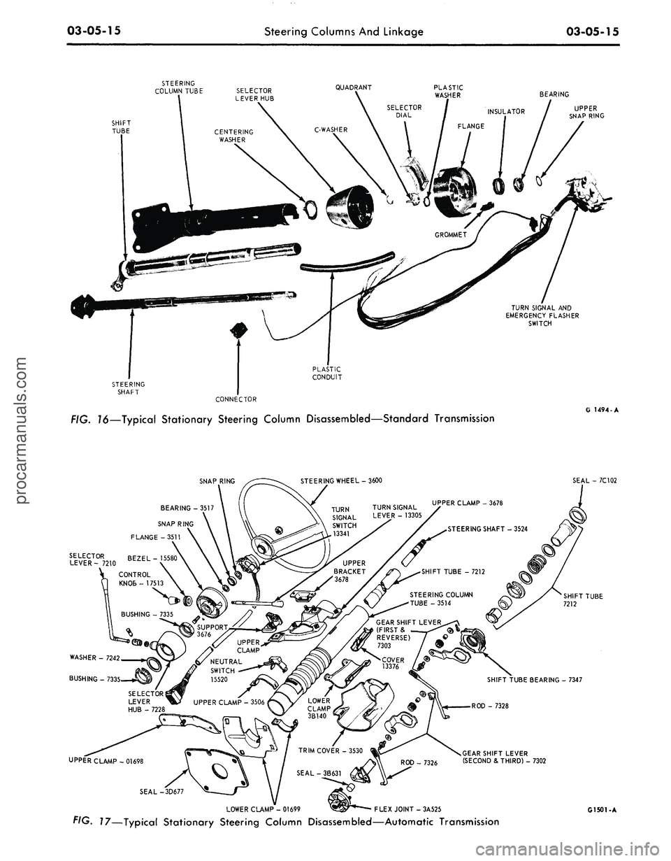
FIG. 16—Typical Stationary Steering Column Disassembled—Standard Transmission
G 1494-A
SNAP RING
STEERING WHEEL-3600
SEAL - 7C102
BEARING -3517
SNAP RING
FLANGE -3511
SELECTOR BEZEL-
LEVER- 7210 ZtL
GEAR SHIFT LEVER
(FIRST
&
REVERSE)
/
7303
/ 9
WASHER - 7242
BUSHING - 733
- 7347
UPPER CLAMP-01698
GEARSHIFT LEVER
(SECOND & THIRD) - 7302
SEAL-
LOWER CLAMP - 01699
^^r**——
FLEX JOINT - 3A525
FIG. 17—Typical Stationary Steering Column Disassembled—Automatic Transmission
G1501-Aprocarmanuals.com
Page 142 of 413
03-07-04
Ford Design Non-Integral Power Steering System
03-07-04
12.
Stop the engine, and check the
control valve and hose connections for
fluid leaks. Correct the cause of any
leaks.
13.
Check the fluid level, and refill
the reservoir if necessary.
14.
With the engine running check
the position of the steering wheel
when the front wheels are in the
straight-ahead position.Do not make
any adjustments until toe-in is
checked.
15.
Keep the engine running, and
check toe-in. If either toe-in or steer-
ing wheel position is not correct make
all necessary adjustments (Part 3-1) at
the spindle connecting rod sleeves.
16.
Check the effort to turn the
wheels in both directions. The effort
should be about equal in both direc-
tions.
POWER CYLINDER
REMOVAL
1.
Disconnect the two fluid lines
from the power cylinder and allow
them to drain into a container.
CENTER LINK
POWER CYLINDER
Tool- T64P-3590-F
G 1654-A
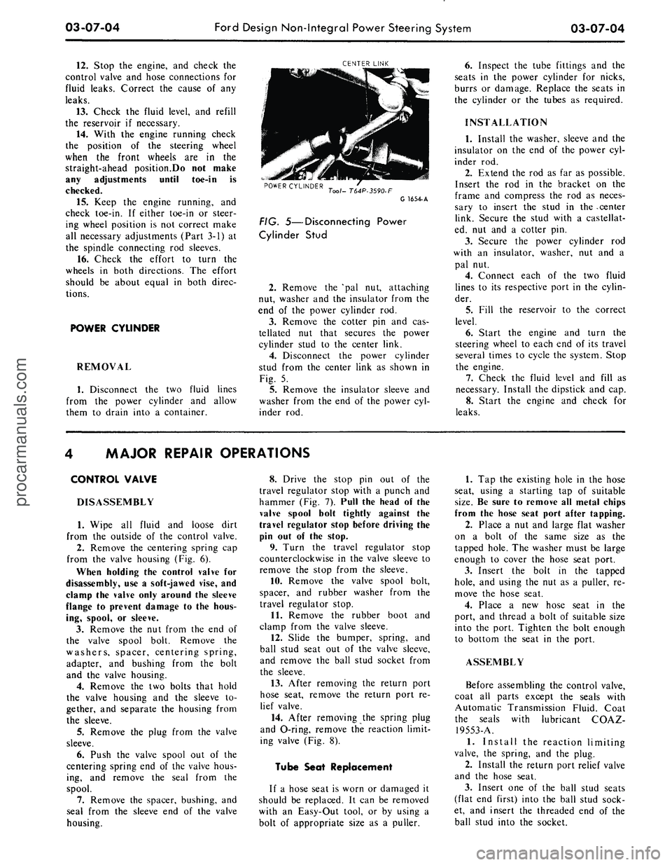
FIG. 5—Disconnecting Power
Cylinder Stud
2.
Remove the 'pal nut, attaching
nut, washer and the insulator from the
end of the power cylinder rod.
3.
Remove the cotter pin and cas-
tellated nut that secures the power
cylinder stud to the center link.
4.
Disconnect the power cylinder
stud from the center link as shown in
Fig. 5.
5.
Remove the insulator sleeve and
washer from the end of the power cyl-
inder rod.
6. Inspect the tube fittings and the
seats in the power cylinder for nicks,
burrs or damage. Replace the seats in
the cylinder or the tubes as required.
INSTALLATION
1.
Install the washer, sleeve and the
insulator on the end of the power cyl-
inder rod.
2.
Extend the rod as far as possible.
Insert the rod in the bracket on the
frame and compress the rod as neces-
sary to insert the stud in the -center
link. Secure the stud with a castellat-
ed, nut and a cotter pin.
3.
Secure the power cylinder rod
with an insulator, washer, nut and a
pal nut.
4.
Connect each of the two fluid
lines to its respective port in the cylin-
der.
5.
Fill the reservoir to the correct
level.
6. Start the engine and turn the
steering wheel to each end of its travel
several times to cycle the system. Stop
the engine.
7.
Check the fluid level and fill as
necessary. Install the dipstick and cap.
8. Start the engine and check for
leaks.
MAJOR REPAIR OPERATIONS
CONTROL VALVE
DISASSEMBLY
1.
Wipe all fluid and loose dirt
from the outside of the control valve.
2.
Remove the centering spring cap
from the valve housing (Fig. 6).
When holding the control valve for
disassembly, use a soft-jawed vise, and
clamp the valve only around the sleeve
flange to prevent damage to the hous-
ing, spool, or sleeve.
3.
Remove the nut from the end of
the valve spool bolt. Remove the
washers, spacer, centering spring,
adapter, and bushing from the bolt
and the valve housing.
4.
Remove the two bolts that hold
the valve housing and the sleeve to-
gether, and separate the housing from
the sleeve.
5.
Remove the plug from the valve
sleeve.
6. Push the valve spool out of the
centering spring end of the valve hous-
ing, and remove the seal from the
spool.
7.
Remove the spacer, bushing, and
seal from the sleeve end of the valve
housing.
8. Drive the stop pin out of the
travel regulator stop with a punch and
hammer (Fig. 7). Pull the head of the
valve spool bolt tightly against the
travel regulator stop before driving the
pin out of the stop.
9. Turn the travel regulator stop
counterclockwise in the valve sleeve to
remove the stop from the sleeve.
10.
Remove the valve spool bolt,
spacer, and rubber washer from the
travel regulator stop.
11.
Remove the rubber boot and
clamp from the valve sleeve.
12.
Slide the bumper, spring, and
ball stud seat out of the valve sleeve,
and remove the ball stud socket from
the sleeve.
13.
After removing the return port
hose seat, remove the return port re-
lief valve.
14.
After removing the spring plug
and O-ring, remove the reaction limit-
ing valve (Fig. 8).
Tube Seat Replacement
If a hose seat is worn or damaged it
should be replaced. It can be removed
with an Easy-Out tool, or by using a
bolt of appropriate size as a puller.
1.
Tap the existing hole in the hose
seat, using a starting tap of suitable
size.
Be sure to remove all metal chips
from the hose seat port after tapping.
2.
Place a nut and large flat washer
on a bolt of the same size as the
tapped hole. The washer must be large
enough to cover the hose seat port.
3.
Insert the bolt in the tapped
hole,
and using the nut as a puller, re-
move the hose seat.
4.
Place a new hose seat in the
port, and thread a bolt of suitable size
into the port. Tighten the bolt enough
to bottom the seat in the port.
ASSEMBLY
Before assembling the control valve,
coat all parts except the seals with
Automatic Transmission Fluid. Coat
the seals with lubricant COAZ-
19553-A.
1.
Install the reaction limiting
valve, the spring, and the plug.
2.
Install the return port relief valve
and the hose seat.
3.
Insert one of the ball stud seats
(flat end first) into the ball stud sock-
et, and insert the threaded end of the
ball stud into the socket.procarmanuals.com
Page 147 of 413

03-08-03
Ford Design Integral Power Steering Gear
03-08-03
factory adjustments will change. These
changes in adjustment do not neces-
sarily affect the satisfactory operation
of the steering gear assembly, and
therefore ordinarily do not require
readjustment unless there is excessive
lash or other malfunctioning.
ADJUSTMENT IN
VEHICLE
The only adjustment which can be
performed is the total over center
position load, to eliminate excessive
lash between the sector and rack
teeth.
1.
Disconnect the pitman arm from
the sector shaft.
2.
Disconnect the fluid return line
at the reservoir, at the same time cap
the reservoir return line pipe.
3.
Place the end of the return line
in a clean container and cycle the
INPUT SHAFT
SECTOR SHAFT
ADJUSTMENT SCREW
C1547- A
FIG.
2—Adjusting Mesh Load
steering wheel in both directions as re-
quired, to discharge the fluid from the
gear.
4.
Remove the ornamental cover
from the steering wheel hub and turn
the steering wheel to 45 degrees from
the left stop.
5.
Using an in-lb torque wrench on
the steering wheel nut, determine the
torque required to rotate the shaft
slowly through an approximately 1/8
turn from the 45 degree position.
6. Turn the steering gear back to
center, then determine the torque re-
quired to rotate the shaft back and
forth across the center position. Loos-
en the adjuster nut, and turn the ad-
juster screw in (Fig. 2) until the read-
ing is 8-9 in-lb greater than the torque
45 degrees from the stop.
Tighten the lock nut while holding
the screw in place.
7.
Recheck the readings and replace
pitman arm and steering wheel hub
cover.
8. Connect the fluid return line to
the reservoir and fill the reservoir with
specified lubricant to the proper level.
REMOVAL AND INSTALLATION
REMOVAL
1.
Disconnect the pressure and the
return lines from the steering gear.
Plug the lines and the ports in the
gear to prevent entry of dirt.
2.
Remove the two bolts that secure
the flex coupling to the steering gear
and to the column.
3.
Raise the vehicle and remove the
sector shaft attaching nut.
4.
Remove the Pitman arm from
the sector shaft with Tool T64P-
3590-F.
Remove the tool from the
Pitman arm. Do not damage the
seals.
5.
If working on a vehicle equipped
with a standard transmission, remove
the clutch release lever retracting
spring to provide clearance for remov-
ing the steering gear.
6. Support the steering gear then
remove the three steering gear attach-
ing bolts.
7.
Work steering gear free of the
flex coupling and remove it from the
vehicle.
8. If the flex coupling stayed on the
input shaft, lift if off the shaft at this
time.
INSTALLATION
1.
Slide the flex coupling into place
on the steering shaft. Turn the steer-
ing wheel so that the spokes are in the
horizontal position.
2.
Center the steering gear input
shaft.
3.
Slide the steering gear input
shaft into the flex coupling and into
place on the frame side rail. Install
the three attaching bolts and torque
them to specification.
4.
Make sure that the wheels are in
the straight ahead position, then in-
stall the Pitman arm on the sector
shaft. Install and tighten the sector
shaft and install and tighten the at-
taching bolts to specification.
5.
Move the flex coupling into
place on the input and steering co-
lumn shaft and install and tighten the
attaching bolts to specification.
6. Connect and tighten the fluid
pressure and the return line to the
steering gear.
7.
Fill the power steering pump and
cycle the steering gear. Check for
leaks and again check the fluid level.
Add fluid as required.
MAJOR REPAIR OPERATIONS
In most cases, complete disassembly
of the power steering gear will not be
necessary. It is suggested that only
those assemblies that are faulty be dis-
assembled. Disassembly and reassem-
bly of the unit and the subassemblies
must be made on a clean workbench.
As in repairing any hydraulically op-
erated unit, cleanliness is of utmost
importance. Therefore, the bench,
tools,
and parts must be kept clean at
all times. Thoroughly clean the exter-
ior of the unit with a suitable solvent
and when necessary, drain as much of
the hydraulic oil as possible. Handle
all parts very carefully to avoid nicks,
burrs,
scratches and dirt, which could
make the parts unfit for use. Do not
clean, wash or soak seals in cleaning
solvent.
VALVE CENTERING
SHIM REPLACEMENT
1.
Hold the steering gear over a
drain pan in an inverted position and
cycle the input shaft several times to
drain the remaining fluid from the
gear.
2.
Mount the gear in a soft-jawed
vise.procarmanuals.com
Page 153 of 413

03-09-01
Saginaw Design Integral Power Steering Gear
03-09-01
PART 3-9 Saginaw Design
Integral Power Steering Gear
COMPONENT INDEX
STEERING GEAR
Cleaning and Inspection (See Page 03-01)
Description
Disassembly and Assembly
Mesh Load Adjustment
Removal and Installation
Overhaul
MODEL APPLICATION
All
Models
Ford
09-01
09-03
09-01
09-02
09-04
Mercury
N/A
N/A
N/A
N/A
N/A
N/A
Meteor
N/A
N/A
N/A
N/A
N/A
N/A
Cougar
N/A
N/A
N/A
N/A
N/A
N/A
Fairlane
N/A
N/A
N/A
N/A
N/A
N/A
Falcon
N/A
N/A
N/A
N/A
N/A
N/A
Montego
N/A
N/A
N/A
N/A
N/A
N/A
Mustang
N/A
N/A
N/A
N/A
N/A
N/A
Lincoln-
Continental
N/A
N/A
N/A
N/A
N/A
N/A
Thunderbird
N/A
N/A
N/A
N/A
N/\
N/A
Continental-
Mark III
N/A
N/A
N/A
N/A
N/A
N/A
A page number indicates that the item is for the vehicle listed at the head of the column.
N/A indicates that the item is not applicable to the vehicle listed.
DESCRIPTION
The Rotary Valve Safety power
steering gear operates entirely on dis-
placing fluid to provide hydraulic fluid
pressure assists only when turning. As
the entire gear assembly is always full
of fluid, all internal components of the
gear are immersed in fluid making
periodic lubrication unnecessary. In
addition, this fluid acts as a cushion
to absorb road shocks that may be
transmitted to the driver. All fluid
passages are internal except the pres-
sure and return hoses between the
gear and pump.
The rotary valve provides a smooth
transmission through the driving range
of steering wheel effort. A torsion bar
transmits the road feel to the driver.
Response of the steering gear to effort
applied to the steering wheel has been
greatly increased.
The rack-piston nut is one piece and
is geared to the sector shaft. Lash be-
tween the sector shaft and rack-piston
nut is maintained by an adjusting
screw which is retained in the end o\'
the shaft uear (Eiiz.l).
IN-VEHICLE ADJUSTMENTS AND REPAIRS
During the breaking in period of
the vehicle, it is probable that some
of the factory adjustments will change.
These changes in adjustment do not
necessarily affect the satisfactory op-
eration of the steering gear assembly
and ordinarily do not require re-ad-
justment unless there is excessive lash
or other malfunctioning. The only ad-
justment that should be performed in
the vehicle is the total over center
position load (mesh load) to eliminate
excessive lash between the sector shaft
and rack teeth.
MESH LOAD ADJUSTMENT
1.
Disconnect the Pitman arm from
the sector shaft and remove the steer-
ing wheel hub.
2.
Disconnect the fluid return line
at the reservoir; at the same time cap
the reservoir return line pipe.
3.
Place the end of the return line
in a clean container and cycle the
steering wheel in both directions as
required, to discharge the fluid from
the gear.
4.
Turn the gear 1/2 turn off cen-
ter (either direction). Using a 24 in-
lb torque wrench on the steering wheel
nut, determine the torque required to
rotate the shaft slowly through a 20
degree arc.
5.
Turn the sear back to center and
repeating the method of reading tor-
que as in Step 4, above, loosen the
adjuster lock nut, turn the screw in-
ward with a 7/32-inch Allen wrench
until the reading is equal to 6 in-lbs
in excess of Step 4 above, and retigh-
ten the lock nut while holding the
screw in place.
6. Recheck the readings and re-
place the Pitman arm and the steering
wheel hub.
7.
Connect the fluid return line to
the reservoir and fill the reservoir
with C1AZ-I9582-A Fluid to the
proper level.
procarmanuals.com
Page 154 of 413
03-09-02
Saginaw Design Integral Power Steering Gear
03-09-02
WORM
ADJUSTER PLUG
TORSION BAR
STUB SHAFT
SEAL
NEEDLE BEARINGS
TEFLON RING
TEFLON SEALS
SECTOR SHAFT
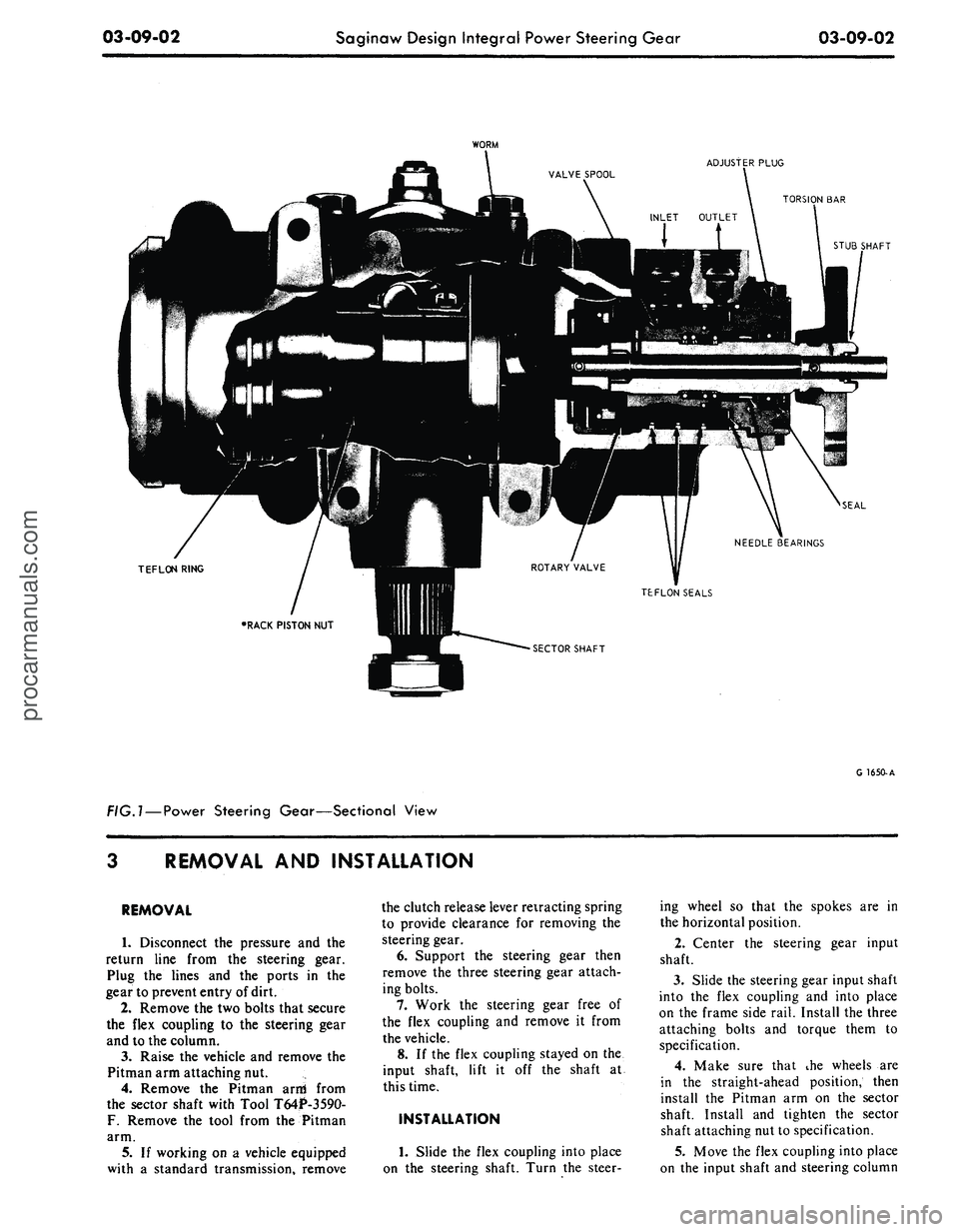
FIG.l —
Power
Steering Gear—Sectional View
G 1650-A
REMOVAL
AND
INSTALLATION
REMOVAL
1.
Disconnect
the
pressure
and the
return line from
the
steering gear.
Plug
the
lines
and the
ports
in the
gear to prevent entry of dirt.
2.
Remove the two bolts that secure
the flex coupling
to the
steering gear
and
to
the column.
3.
Raise
the
vehicle
and
remove
the
Pitman arm attaching nut.
4.
Remove
the
Pitman arni from
the sector shaft with Tool T64P-3590-
F.
Remove
the
tool from
the
Pitman
arm.
5.
If
working
on a
vehicle equipped
with
a
standard transmission, remove
the clutch release lever retracting spring
to provide clearance
for
removing
the
steering gear.
6. Support
the
steering gear then
remove
the
three steering gear attach-
ing bolts.
7.
Work
the
steering gear free
of
the flex coupling
and
remove
it
from
the vehicle.
8.
If
the flex coupling stayed
on the
input shaft, lift
it off the
shaft
at
this time.
INSTALLATION
1.
Slide
the
flex coupling into place
on
the
steering shaft. Turn
the
steer-
ing wheel
so
that
the
spokes
are in
the horizontal position.
2.
Center
the
steering gear input
shaft.
3.
Slide the steering gear input shaft
into
the
flex coupling
and
into place
on
the
frame side rail. Install the three
attaching bolts
and
torque them
to
specification.
4.
Make sure that
ihe
wheels
are
in
the
straight-ahead position, then
install
the
Pitman
arm on the
sector
shaft. Install
and
tighten
the
sector
shaft attaching nut to specification.
5.
Move the flex coupling into place
on
the
input shaft
and
steering columnprocarmanuals.com
Page 163 of 413

03-10-02
Ford-Thompson Power Steering Pump
03-10-02
LOWER PRESSURE
PLATE 3D590
SPRING-3D601
UPPER PRESSURE
PLATE -3A645
RETAINER END
PLATE-3D589
CAM AND ROTOR
ASSEMBLY-
-3D607
SCREW AND WASHER
ASSEMBLY-379376-S
PULLEY-3D673
PUMP SHAFT
SEAL 3B592
PLATE AND BUSHING
ASSEMBLY-3D643
0-RING
382744-S
HOUSING GASKET
3A760
G1343-B
FIG. 2—Power Steering Pump Disassembled
To adjust the belt on 8 cyl. engines
loosen the mounting bolt in the ad-
justing slot and the nut directly above
the adjusting slot. Place a suitable pry
bar between the cast boss on the
pump mounting bracket and the cast
boss on the pump cover plate and pry
upward to correct tension.
Do not pry against the reservoir to
obtain proper belt load as it can be
deformed and cause a leak.
3.
Recheck the belt tension. When
the tension has been correctly adjusted,
tighten the bolts and the fiut to speci-
fication (Part 3-13).
POWER STEERING
PUMP DRIVE BELT
REPLACEMENT
1.
Loosen the idler pulley attaching
bolts and remove the compressor drive
belt if equipped with an air condition-
er.
2.
Loosen 3 bolts and one nut at-
taching the power steering pump to
the pump bracket, and remove the
pump drive belt.
3.
Position the power steering
pump drive belt on the pulleys.
4.
Adjust the drive belt tension as
outlined in Section 2 to specification
(Part 3-13) and tighten the pump at-
taching bolts and one nut to specifica-
tion.
5.
Install the compressor drive belt
if equipped with an air conditioner
and adjust to specification (Part 16).
REMOVAL AND INSTALLATION
POWER STEERING
PUMP REPLACEMENT
EIGHT CYLINDER
WITHOUT AIR
CONDITIONER AND
ALL SIX CYLINDER
1.
Remove the power steering fluid
from the pump reservoir by discon-
necting the fluid return hose at the
reservoir, and allow the fluid to drain
into a suitable container.
2.
Disconnect the pressure hose
from the pump.
3.
Remove 3 bolts from the front of
the pump and the one nut at the rear
(rear nut on 8 cyl. engines only) that
attach the pump to the mounting
bracket; disconnect the belt from the
pulley and remove the pump from the
vehicle.
4.
Position the pump to the mount-
ing bracket and install the 3 bolts at
the front of pump and (rear nut on 8
cyl.
engines only) the 1 nut at the
rear. Torque to specification.
5.
Place the belt on the pulley and
adjust the belt tension (Section 2) with
Tool T63L-8620-A and tighten the
bolts and nut to specifications.
6. Torque the pressure hose fitting
hex nut to specification. Then, connect
the pressure hose to the fitting and
torque the hose nut to specification.
7.
Connect the hose to the pump.
Then, tighten the clamp.
8. Fill the power steering pump res-
ervoir with transmission fluid C1AZ-
19582-A and cycle the system to re-
move air from the steering gear sys-
tem.
9. Check for leaks and again check
the fluid level. Add fluid as necessary.procarmanuals.com
Page 164 of 413
03-10-03
Ford-Thompson Power Steering Pump
03-10-03
EIGHT CYLINDER WITH
AIR CONDITIONER
1.
Remove the power steering fluid
from the pump reservoir by discon-
necting the fluid return hose from the
reservoir and allow the fluid to drain
in a suitable container.
2.
Disconnect the pressure hose
from the pump.
3.
Remove 3 bolts from the front of
the pump and the one nut at the rear
that attach the pump to the mounting
bracket and remove the drive belt
from the pump pulley.
4.
Loosen the upper pump bracket-
to-engine attaching bolt and remove
the bolt in the belt adjusting slot. Re-
move the pump.
5.
Position the pump to the bracket
and install the bracket-to-pump at-
taching bolts and nuts. Tighten to spe-
cifications.
6. Place the belt on the pump pul-
ley. Adjust the belt tension as outlined
in Section 2 and tighten the bolts and
nut to specification.
7.
Torque the pressure hose fitting
hex nut to specification. Then, connect
the pressure hose to the fitting and
torque the hose nut to specification.
8. Connect the return hose to the
power steering pump and tighten the
clamp.
9. Fill the pump with automatic
transmission fluid C1AZ-19582-A.
Bleed the air from the system (Part
3-1) and check for leaks and again
check the fluid level. Add fluid as re-
quired.
POWER STEERING PUMP
PULLEY REPLACEMENT
REMOVAL
1.
Drain as much of the fluid as
possible from the pump through filler
pipe.
2.
Install a 3/8-16 inch capscrew in
the end of the pump shaft to prevent
damage to the shaft end by the tool
screw.
3.
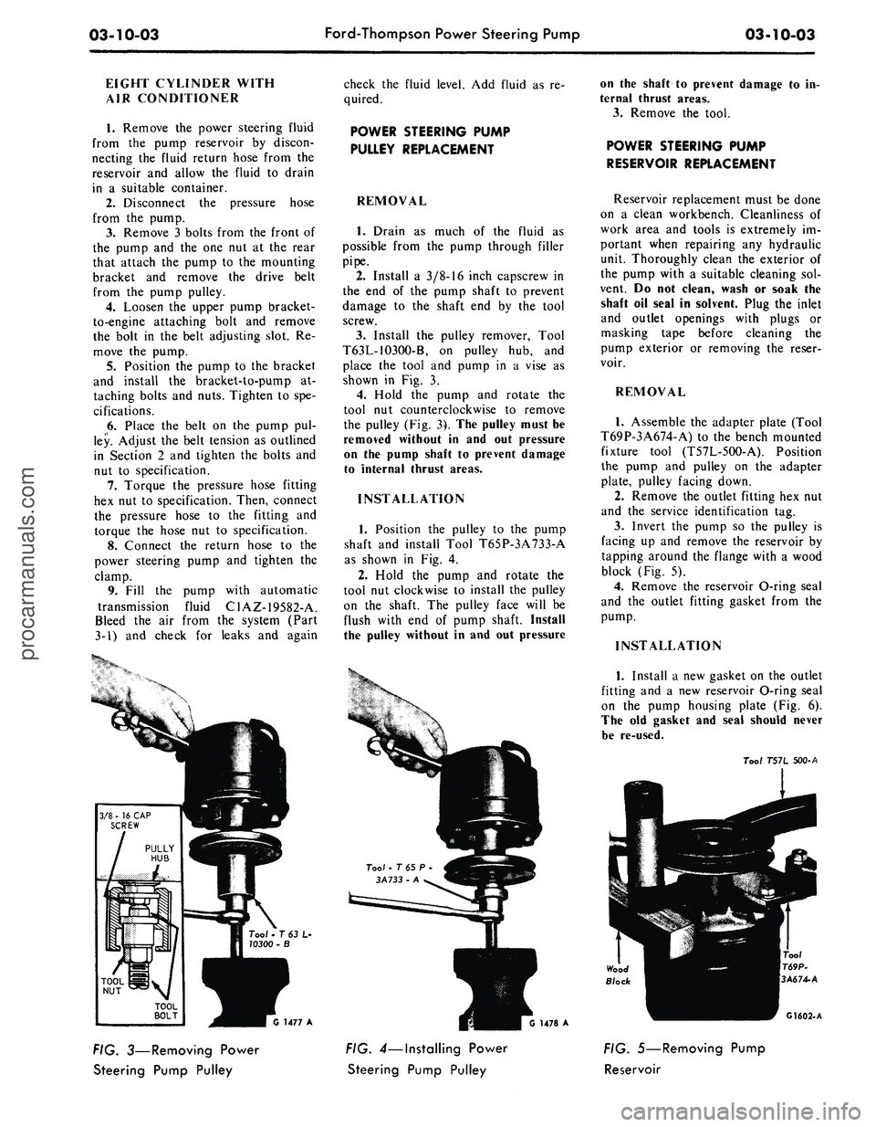
Install the pulley remover, Tool
T63L-1O3OO-B, on pulley hub, and
place the tool and pump in a vise as
shown in Fig. 3.
4.
Hold the pump and rotate the
tool nut counterclockwise to remove
the pulley (Fig. 3). The pulley must be
removed without in and out pressure
on the pump shaft to prevent damage
to internal thrust areas.
INSTALLATION
1.
Position the pulley to the pump
shaft and install Tool T65P-3A733-A
as shown in Fig. 4.
2.
Hold the pump and rotate the
tool nut clockwise to install the pulley
on the shaft. The pulley face will be
flush with end of pump shaft. Install
the pulley without in and out pressure
on the shaft to prevent damage to in-
ternal thrust areas.
3.
Remove the tool.
POWER STEERING PUMP
RESERVOIR REPLACEMENT
Reservoir replacement must be done
on a clean workbench. Cleanliness of
work area and tools is extremely im-
portant when repairing any hydraulic
unit. Thoroughly clean the exterior of
the pump with a suitable cleaning sol-
vent. Do not clean, wash or soak the
shaft oil seal in solvent. Plug the inlet
and outlet openings with plugs or
masking tape before cleaning the
pump exterior or removing the reser-
voir.
REMOVAL
1.
Assemble the adapter plate (Tool
T69P-3A674-A) to the bench mounted
fixture tool (T57L-5OO-A). Position
the pump and pulley on the adapter
plate, pulley facing down.
2.
Remove the outlet fitting hex nut
and the service identification tag.
3.
Invert the pump so the pulley is
facing up and remove the reservoir by
tapping around the flange with a wood
block (Fig. 5).
4.
Remove the reservoir O-ring seal
and the outlet fitting gasket from the
pump.
INSTALLATION
Tool • T 63 L-
10300 -
G 1477 A
FIG. 3—Removing Power
Steering Pump Pulley
1478 A
FIG. 4—Installing Power
Steering Pump Pulley
1.
Install a new gasket on the outlet
fitting and a new reservoir O-ring seal
on the pump housing plate (Fig. 6).
The old gasket and seal should never
be re-used.
Too/
T57L 500-A
G1602-A
FIG. 5—Removing Pump
Reservoirprocarmanuals.com
Page 169 of 413
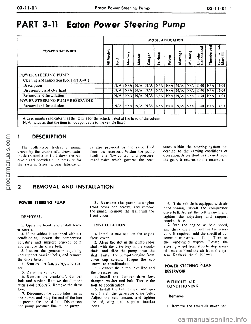
03-11-01
Eaton Power Steering Pump
03-11-01
PART 3-11 Eaton Power Steering Pump
COMPONENT INDEX
MODEL APPLICATION
3
§>
"o
4
POWER STEERING PUMP
Cleaning and Inspection (See Part 03-01)
Description
N/A
N/A
N/A
N/A
N/A
N/A
N/A
N/A
11-01
N/A
11-01
Disassembly and Overhaul
N/A
N/A
N/A
N/A
N/A
N/A
N/A
N/A
11-03
N/A
11-03
Removal and Installation
N/A
N/A
N/A
N/A
N/A
N/A
N/A
N/A
11-01
N/A
11-01
POWER STEERING PUMP RESERVOIR
Removal and Installation
N/A
N/A
N/A
N/A
N/A
N/A
N/A
N/A
11-01
N/A
11-01
A page number indicates that the item is for the vehicle listed at the head of the column.
N/A indicates that the item is not applicable to the vehicle listed.
l
DESCRIPTION
The roller-type hydraulic pump,
driven by the crankshaft, draws auto-
matic transmission fluid down the res-
ervoir and provides fluid pressure for
the system. Steering gear lubrication
is also provided by the same fluid
from the reservoir. Within the pump
itself is a flow-control and pressure-
relief valve which governs the pres-
sures within the steering system ac-
cording to the varying conditions of
operation. After fluid has passed from
the gear, it returns to the reservoir.
REMOVAL AND INSTALLATION
POWER STEERING PUMP
REMOVAL
1.
Open the hood, and install fend-
er covers.
2.
If the vehicle is equipped with air
conditioning, loosen the compressor
adjusting and support bracket bolts
and remove the drive belt.
3.
Loosen the generator adjusting
and support bracket bolts, and remove
the drive belts.
4.
Remove the fan, pulley, and spa-
cer.
5.
Raise the vehicle.
6. Remove the crankshaft damper
bolt and washer. Remove the damper
with Tool 6306-AG. Remove the drive
key.
7.
Disconnect the pump inlet line at
the pump, and plug the end of the line
to prevent the loss of fluid. Disconnect
the pump pressure line at the pump.
8. Remove the pump-to-engine
front cover cap screws, and remove
the pump. Remove the seal from the
front cover.
INSTALLATION
1.
Install a new seal on the engine
front cover.
2.
Align the slot in the pump rotor
shaft with the drive key in the crank-
shaft, and slide the pump onto the
shaft. Install the pump-to-engine front
cover cap screws. Torque the cap
screws to specification.
3.
Connect the pump inlet line and
the pressure line.
4.
Install the damper drive key,
damper, washer and bolt. Torque the
bolt to specification.
5.
Install the fan, pulley, and spa-
cer. Install the generator drive belts.
Adjust the belt tension, and tighten
the adjusting and support bracket
bolts.
6. If the vehicle is equipped with air
conditioning, install the compressor
drive belt. Adjust the belt tension, and
tighten the adjusting and support
bracket bolts.
7.
Run the engine at idle speed,
and check the fluid level in the reser-
voir. If required, add the specified au-
tomatic transmission fluid. Turn on
the windshield wipers. Rotate the
steering wheel from stop to stop sever-
al times to bleed the air from the sys-
tem. Recheck the fluid level.
POWER STEERING PUMP
RESERVOIR
WITHOUT AIR
CONDITIONING
Removal
1.
Remove the reservoir cover andprocarmanuals.com