1969 FORD MUSTANG seats
[x] Cancel search: seatsPage 103 of 413
03-02-27
Suspension
03-02-27
MAJOR
REPAIR OPERATIONS
FRONT
SUSPENSION UPPER
ARM
BUSHINGS—ARM
REMOVED
FORD, MERCURY,
METEOR, THUNDERBIRD,
CONTINENTAL MARK III
1.
Remove the nuts and washers
from both ends of the upper arm inner
shaft.
2.
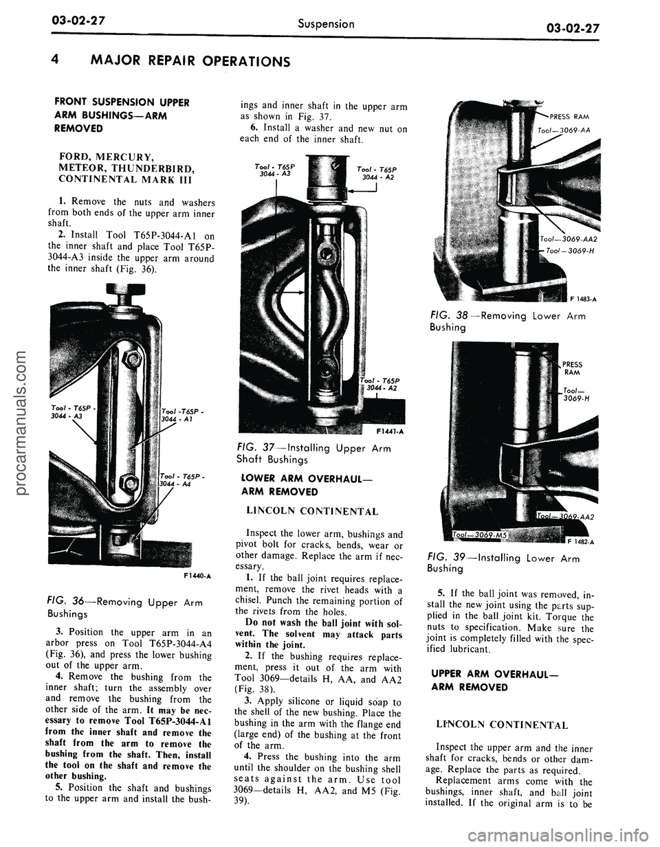
Install Tool T65P-3044-A1 on
the inner shaft and place Tool T65P-
3044-A3 inside the upper arm around
the inner shaft (Fig. 36).
F1440-A
FIG.
36—Removing Upper Arm
Bushings
3.
Position the upper arm in an
arbor press on Tool T65P-3044-A4
(Fig. 36), and press the lower bushing
out of the upper arm.
4.
Remove the bushing from the
inner shaft; turn the assembly over
and remove the bushing from the
other side of the arm. It may be nec-
essary to remove Tool T65P-3044-A1
from the inner shaft and remove the
shaft from the arm to remove the
bushing from the shaft. Then, install
the tool on the shaft and remove the
other bushing.
5. Position the shaft and bushings
to the upper arm and install the bush-
ings and inner shaft in the upper arm
as shown in Fig. 37.
6. Install a washer and new nut on
each end of the inner shaft.
PRESS
RAM
Tool—3069-AA
Tool
- T65P
3044
- A3
Tool
- T65P
3044
- A2
F1441-A
FIG.
37—Installing Upper Arm
Shaft
Bushings
LOWER
ARM OVERHAUL-
ARM
REMOVED
LINCOLN CONTINENTAL
Inspect the lower arm, bushings and
pivot bolt for cracks, bends, wear or
other damage. Replace the arm if nec-
essary.
1. If the ball joint requires replace-
ment, remove the rivet heads with a
chisel. Punch the remaining portion of
the rivets from the holes.
Do not wash the ball joint with sol-
vent. The solvent may attack parts
within the joint.
2.
If the bushing requires replace-
ment, press it out of the arm with
Tool 3069—details H, AA, and AA2
(Fig. 38).
3.
Apply silicone or liquid soap to
the shell of the new bushing. Place the
bushing in the arm with the flange end
(large end) of the bushing at the front
of the arm.
4.
Press the bushing into the arm
until the shoulder on the bushing shell
seats against the arm. Use tool
3069—details H, AA2, and M5 (Fig.
39).
F
1483-A
FIG.
38—Removing Lower Arm
Bushing
PRESS
RAM
1482-A
FIG.
39—Installing Lower Arm
Bushing
5.
If the ball joint was removed, in-
stall the new joint using the parts sup-
plied in the ball joint kit. Torque the
nuts to specification. Make sure the
joint is completely filled with the spec-
ified lubricant.
UPPER
ARM OVERHAUL-
ARM
REMOVED
LINCOLN CONTINENTAL
Inspect the upper arm and the inner
shaft for cracks, bends or other dam-
age.
Replace the parts as required.
Replacement arms come with the
bushings, inner shaft, and ball joint
installed. If the original arm is to beprocarmanuals.com
Page 142 of 413
03-07-04
Ford Design Non-Integral Power Steering System
03-07-04
12.
Stop the engine, and check the
control valve and hose connections for
fluid leaks. Correct the cause of any
leaks.
13.
Check the fluid level, and refill
the reservoir if necessary.
14.
With the engine running check
the position of the steering wheel
when the front wheels are in the
straight-ahead position.Do not make
any adjustments until toe-in is
checked.
15.
Keep the engine running, and
check toe-in. If either toe-in or steer-
ing wheel position is not correct make
all necessary adjustments (Part 3-1) at
the spindle connecting rod sleeves.
16.
Check the effort to turn the
wheels in both directions. The effort
should be about equal in both direc-
tions.
POWER CYLINDER
REMOVAL
1.
Disconnect the two fluid lines
from the power cylinder and allow
them to drain into a container.
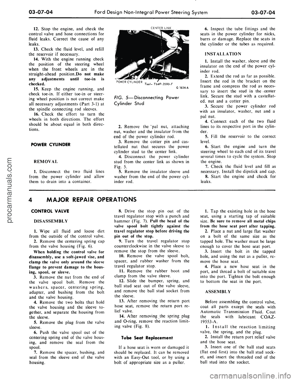
CENTER LINK
POWER CYLINDER
Tool- T64P-3590-F
G 1654-A
FIG. 5—Disconnecting Power
Cylinder Stud
2.
Remove the 'pal nut, attaching
nut, washer and the insulator from the
end of the power cylinder rod.
3.
Remove the cotter pin and cas-
tellated nut that secures the power
cylinder stud to the center link.
4.
Disconnect the power cylinder
stud from the center link as shown in
Fig. 5.
5.
Remove the insulator sleeve and
washer from the end of the power cyl-
inder rod.
6. Inspect the tube fittings and the
seats in the power cylinder for nicks,
burrs or damage. Replace the seats in
the cylinder or the tubes as required.
INSTALLATION
1.
Install the washer, sleeve and the
insulator on the end of the power cyl-
inder rod.
2.
Extend the rod as far as possible.
Insert the rod in the bracket on the
frame and compress the rod as neces-
sary to insert the stud in the -center
link. Secure the stud with a castellat-
ed, nut and a cotter pin.
3.
Secure the power cylinder rod
with an insulator, washer, nut and a
pal nut.
4.
Connect each of the two fluid
lines to its respective port in the cylin-
der.
5.
Fill the reservoir to the correct
level.
6. Start the engine and turn the
steering wheel to each end of its travel
several times to cycle the system. Stop
the engine.
7.
Check the fluid level and fill as
necessary. Install the dipstick and cap.
8. Start the engine and check for
leaks.
MAJOR REPAIR OPERATIONS
CONTROL VALVE
DISASSEMBLY
1.
Wipe all fluid and loose dirt
from the outside of the control valve.
2.
Remove the centering spring cap
from the valve housing (Fig. 6).
When holding the control valve for
disassembly, use a soft-jawed vise, and
clamp the valve only around the sleeve
flange to prevent damage to the hous-
ing, spool, or sleeve.
3.
Remove the nut from the end of
the valve spool bolt. Remove the
washers, spacer, centering spring,
adapter, and bushing from the bolt
and the valve housing.
4.
Remove the two bolts that hold
the valve housing and the sleeve to-
gether, and separate the housing from
the sleeve.
5.
Remove the plug from the valve
sleeve.
6. Push the valve spool out of the
centering spring end of the valve hous-
ing, and remove the seal from the
spool.
7.
Remove the spacer, bushing, and
seal from the sleeve end of the valve
housing.
8. Drive the stop pin out of the
travel regulator stop with a punch and
hammer (Fig. 7). Pull the head of the
valve spool bolt tightly against the
travel regulator stop before driving the
pin out of the stop.
9. Turn the travel regulator stop
counterclockwise in the valve sleeve to
remove the stop from the sleeve.
10.
Remove the valve spool bolt,
spacer, and rubber washer from the
travel regulator stop.
11.
Remove the rubber boot and
clamp from the valve sleeve.
12.
Slide the bumper, spring, and
ball stud seat out of the valve sleeve,
and remove the ball stud socket from
the sleeve.
13.
After removing the return port
hose seat, remove the return port re-
lief valve.
14.
After removing the spring plug
and O-ring, remove the reaction limit-
ing valve (Fig. 8).
Tube Seat Replacement
If a hose seat is worn or damaged it
should be replaced. It can be removed
with an Easy-Out tool, or by using a
bolt of appropriate size as a puller.
1.
Tap the existing hole in the hose
seat, using a starting tap of suitable
size.
Be sure to remove all metal chips
from the hose seat port after tapping.
2.
Place a nut and large flat washer
on a bolt of the same size as the
tapped hole. The washer must be large
enough to cover the hose seat port.
3.
Insert the bolt in the tapped
hole,
and using the nut as a puller, re-
move the hose seat.
4.
Place a new hose seat in the
port, and thread a bolt of suitable size
into the port. Tighten the bolt enough
to bottom the seat in the port.
ASSEMBLY
Before assembling the control valve,
coat all parts except the seals with
Automatic Transmission Fluid. Coat
the seals with lubricant COAZ-
19553-A.
1.
Install the reaction limiting
valve, the spring, and the plug.
2.
Install the return port relief valve
and the hose seat.
3.
Insert one of the ball stud seats
(flat end first) into the ball stud sock-
et, and insert the threaded end of the
ball stud into the socket.procarmanuals.com
Page 144 of 413
03-07-06
Ford Design Non-Integral Power Steering System
03-07-06
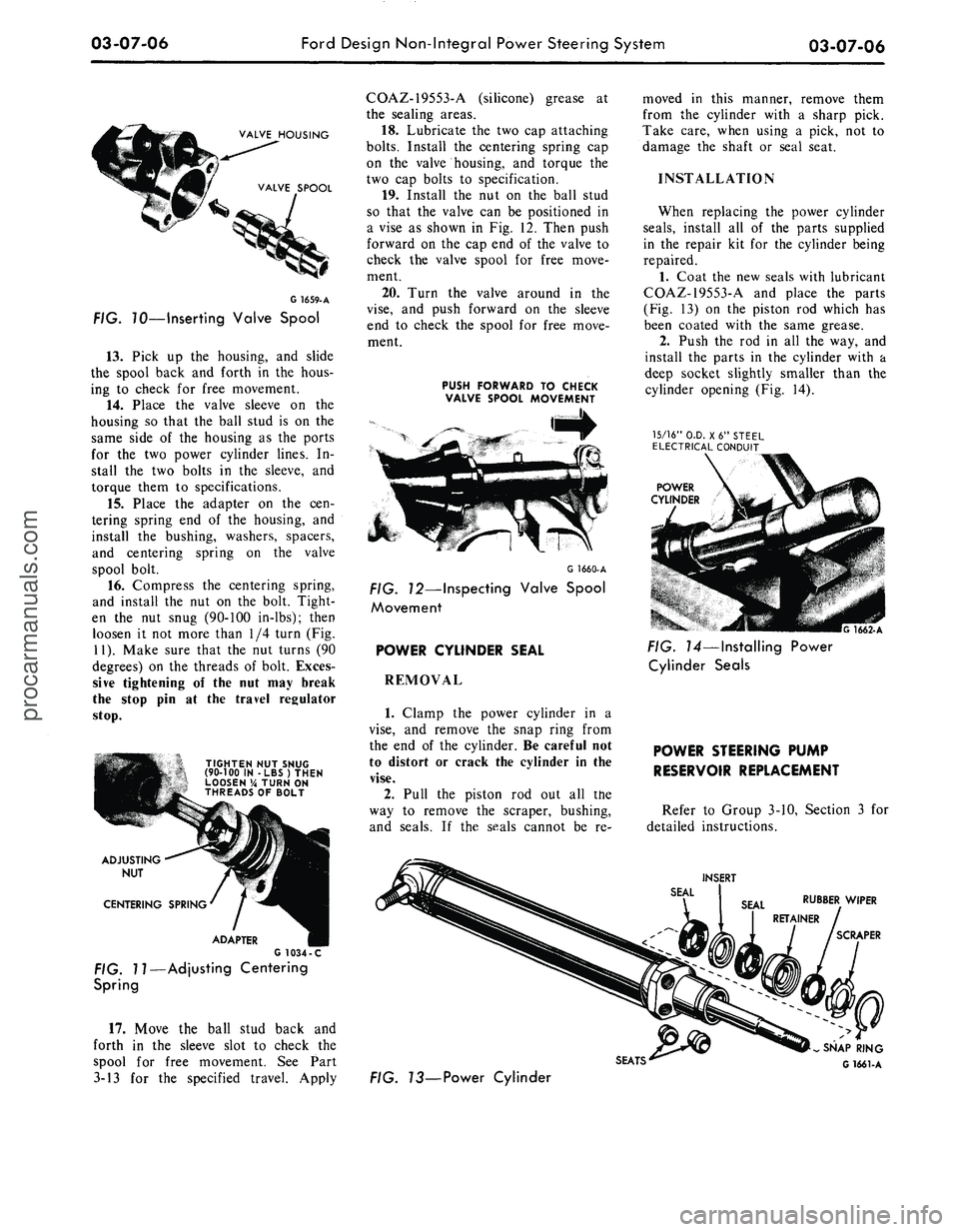
VALVE HOUSING
VALVE SPOOL
G
1659-
A
FIG. 70—Inserting Valve Spool
13.
Pick up the housing, and slide
the spool back and forth in the hous-
ing to check for free movement.
14.
Place the valve sleeve on the
housing so that the ball stud is on the
same side of the housing as the ports
for the two power cylinder lines. In-
stall the two bolts in the sleeve, and
torque them to specifications.
15.
Place the adapter on the cen-
tering spring end of the housing, and
install the bushing, washers, spacers,
and centering spring on the valve
spool bolt.
16.
Compress the centering spring,
and install the nut on the bolt. Tight-
en the nut snug (90-100 in-lbs); then
loosen it not more than 1/4 turn (Fig.
11).
Make sure that the nut turns (90
degrees) on the threads of bolt. Exces-
sive tightening of the nut may break
the stop pin at the travel regulator
stop.
TIGHTEN NUT SNUG
(90-100 IN -LBS) THEN
LOOSEN % TURN ON
THREADS OF BOLT
ADJUSTING
NUT
CENTERING SPRING
ADAPTER
G 1034 -C
FIG. 11—Adjusting Centering
Spring
17.
Move the ball stud back and
forth in the sleeve slot to check the
spool for free movement. See Part
3-13 for the specified travel. Apply
COAZ-19553-A (silicone) grease at
the sealing areas.
18.
Lubricate the two cap attaching
bolts.
Install the centering spring cap
on the valve housing, and torque the
two cap bolts to specification.
19.
Install the nut on the ball stud
so that the valve can be positioned in
a vise as shown in Fig. 12. Then push
forward on the cap end of the valve to
check the valve spool for free move-
ment.
20.
Turn the valve around in the
vise,
and push forward on the sleeve
end to check the spool for free move-
ment.
PUSH FORWARD TO CHECK
VALVE SPOOL MOVEMENT
G 1660-A
FIG. 12—Inspecting Valve Spool
Movement
POWER CYLINDER SEAL
REMOVAL
1.
Clamp the power cylinder in a
vise,
and remove the snap ring from
the end of the cylinder. Be careful not
to distort or crack the cylinder in the
vise.
2.
Pull the piston rod out all the
way to remove the scraper, bushing,
and seals. If the seals cannot be re-
moved in this manner, remove them
from the cylinder with a sharp pick.
Take care, when using a pick, not to
damage the shaft or seal seat.
INSTALLATION
When replacing the power cylinder
seals,
install all of the parts supplied
in the repair kit for the cylinder being
repaired.
1.
Coat the new seals with lubricant
COAZ-19553-A and place the parts
(Fig. 13) on the piston rod which has
been coated with the same grease.
2.
Push the rod in all the way, and
install the parts in the cylinder with a
deep socket slightly smaller than the
cylinder opening (Fig. 14).
15/16"
O.D. X6" STEEL
ELECTRICAL CONDUIT
POWER
CYLINDER
G 1662-A
FIG. 14—Installing Power
Cylinder Seals
POWER STEERING PUMP
RESERVOIR REPLACEMENT
Refer to Group 3-10, Section 3 for
detailed instructions.
INSERT
RUBBER WIPER
SCRAPER
SEATS'
FIG. 73—Power Cylinder
SNAP RING
G 1661-Aprocarmanuals.com
Page 150 of 413

03-08-06
Ford Design Integral Power Steering Gear
03-08-06
VALVE HOUSING
7W-T65P
C1239 -A
FIG. 7—Removing or Installing Lock
Nut
drain the remaining fluid from the
gear.
2.
Mount the gear in a soft-jawed
vise.
3.
Remove the lock nut and the
brass washer from the adjusting screw.
4.
Turn the input shaft to either
stop then, turn it back approximately
1 3/4 turns to center the gear.
5.
Remove the two sector shaft
cover attaching screws and the
identif-
ication tag.
6. Tap the lower end of the sector
shaft with a soft-hammer to loosen it,
then lift the cover and shaft from the
housing as an assembly. Discard the
O-ring.
7.
Turn the sector shaft cover coun-
terclockwise off the adjuster screw.
8. Remove the four valve housing
attaching bolts. Lift the valve housing
from the steering gear housing while
holding the piston to prevent it from
rotating off the worm shaft. Remove
the valve housing and the lube passage
O-rings and discard them.
9. Stand the valve body and piston
on end with the piston end down. Ro-
tate the input shaft counterclockwise
out of the piston allowing the ball
bearings to drop into the piston.
10.
Place a cloth over the open end
of the piston and turn it upside down
to remove the balls.
11.
Remove the two screws that at-
tach the ball guide clamp (Fig. 6) to
the ball nut and remove the clamp and
the guides.
12.
Install the valve body assembly
in the holding fixture (do not clamp
in a vise) and remove the lock nut and
the attaching nut as shown in Fig. 7.
13.
Carefully slide the input shaft,
worm and valve assembly out of the
valve housing. Due to the close diame-
trical clearance between the spool and
housing, the slightest cocking of the
spool may cause it to jam in the hous-
ing.
14.
Remove the shim from the
valve housing bore.
OIL SEAL
INLET TUBE SEAT
OUTLET TUBE SEAT
DUST SEAL
G1549-A
FIG.
8—Valve Housing Disassembled
Too/-T<
Tool-
T57L-500-A ,^^^
G1364-A
FIG. 9—Removing Bearing and Oil
Seal
PARTS REPAIR
OR REPLACEMENT
Valve Housing
1.
Remove the dust seal (Fig. 8)
from the rear of the valve housing
with Tools T59L-100-B and T58L-
101-A and discard the seal.
2.
Remove the snap ring from the
valve housing.
3.
Turn the fixture to place the
valve housing in an inverted position.
4.
Insert special tool in the valve
body assembly opposite the seal end
and gently tap the bearing and seal
out of the housing as shown in Fig.
9. Discard the seal. Caution must be
exercised when inserting and removing
the tool to prevent damage to the
valve bore in the housing.
5.
Remove the fluid inlet and outlet
tube seats with an EZ-out if they are
damaged.
Press Ra
Tool-
T65P-3524-A7
G1363-A
FIG. 10—Installing Valve Housing
Bearing
6. Coat the fluid inlet and outlet
tube seats with vaseline and position
them in the housing. Install and tight-
en the tube nuts to press the seats to
the proper location.
7.
Coat the bearing and seal surface
of the housing with a film of vaseline.
8. Position the bearing in the valve
housing. Seat the bearing in the valve
housing with the tool shown in Fig.
10.
Make sure that the bearing is
free to rotate.
9. Dip the new oil seal in gear lu-
bricant; then, place it in the housing
with the metal side of the seal facing
outward. Drive the seal into the hous-
ing until the outer edge of seal does
not quite clear the snap ring groove
(Fig. 11).
10.
Place the snap ring in the hous-
ing; then, drive on the ring with the
tool shown in Fig. 11 until the snap
ring seats in its groove to properly lo-
cate the seal.procarmanuals.com
Page 168 of 413
03-10-07
Ford-Thompson Power Steering Pump
03-10-07
15.
Place small amounts of vaseline
on the pump housing plate to hold the
cover gasket in place. Install the gas-
ket on the pump housing plate.
16.
Insert the pressure plate springs
into the pockets in the pump valve as-
sembly. Vaseline may be placed in the
spring pockets to hold the springs in
position (Fig. 17).
17.
Using Tool T69P-3B586-A,
plug the intake hole in the housing
(Fig. 17).
18.
Lubricate the inside of the
housing and the housing cover seal
with C1AZ-19582-A lubricant. Fabri-
cate two studs (3/8-16x1.55 ) to be
used as positioning guides. Install one
in the housing plate bolt hole closest
to the drain hole and one in the bolt
hole diametrically opposite.
19.
Align the small diameter lube
hole in the housing rim with the lube
hole in the housing plate.
20.
Install the housing, applying an
even, downward pressure. The pres-
sure plate springs must not be jarred
and moved out of position. Remove
the guide studs.
21.
Install the housing retaining
bolts finger tight.
22.
Remove Tool T69P-3B586-A.
23.
Torque the retaining bolts even-
ly to 28-32 ft-lbs until the housing
flange contacts the gasket.
24.
Install a 3/8x16 hex head
screw, finger tight, into the end of the
rotor shaft. Using a torque wrench,
check the input torque of the shaft
(Fig. 18). The torque should not ex-
ceed 15 in-lbs. If it does, loosen the
retaining bolts slightly, rotate the
rotor shaft, retorque the bolts evenly
and again check the shaft torque. The
pump must not be used if the shaft
torque exceeds 15 in-lbs.
25.
Release the pin in the bench
holding fixture and agitate the pump
assembly back and forth. If there is a
rattle, the pressure plate springs have
fallen out of their seats and must be
reinstalled.
26.
Install the reservoir O-ring on
the housing plate being careful not to
twist the O-ring. Apply vaseline to the
seal and to the ID of the reservoir
flange.
27.
Install the reservoir, aligning
the notch in the reservoir flange with
the notch in the OD of the pump
housing plate and bushing assembly.
Using only a plastic or rubber ham-
mer, tap at the rear on the outer cor-
ners of the reservoir to avoid damage.
28.
Inspect the assembly to deter-
mine if the reservoir is seated on the
housing plate.
29.
Install the service identification
tag on the outlet valve fitting.
30.
Install the outlet valve fitting
nut and torque to 43-47 ft-lbs.
31.
Invert the pump assembly.
32.
If the pulley was removed, in-
stall the correct pulley using Tool
T65P-3A733-A.procarmanuals.com
Page 201 of 413
04-02-04
Rear Axle — Removable Carrier Type
04-02-04
IN-VEHICLE ADJUSTMENTS AND REPAIRS
REAR AXLE SHAFT, WHEEL
BEARING AND OIL SEAL
REPLACEMENT
The rear axle shafts, wheel bear-
ings,
and oil seal can be replaced
without removing the differential as-
sembly from the axle housing.
REMOVAL OF
AXLE SHAFT
Synthetic wheel bearing seals are
used in production only. Removal and
insertion of rear axle shafts must be
performed with caution. The entire
length of the shaft (including spline)
up to the seal journal must pass
through the seal without cutting of the
seal element during axle removal or
installation will result in early seal fai-
lure.
Leather seals only will be used as
service replacement for synthetic
wheel bearing seals.
1.
Remove the wheel cover, wheel
and tire from the brake drum.
2.
Remove the nuts that secure the
brake drum to the axle shaft flange,
then remove the drum from flange.
3.
Working through the hole pro-
vided in each axle shaft flange, re-
move the nuts that secure the wheel
bearing retainer plate. Then pull the
axle shaft assembly out of the axle
housing (Fig. 4). The brake backing
plate must not be dislodged. Install
one nut to hold the plate in place after
the axle shaft is removed.
Too/-4235-C
E1032-D
FIG. 4—Removing Axle Shaft
REMOVAL OF REAR
WHEEL BEARING AND
SEAL
Synthetic seals must not be cleaned,
soaked or washed in cleaning solvents.
Removal of the wheel bearings from
the axle shaft makes them unfit for
further use.
1.
On all models except Ford, Mer-
cury or Meteor, if the rear wheel
bearing is to be replaced, loosen the
inner retainer ring by nicking it deeply
with a cold chisel in several places
(Fig. 5). It will then slide off easily.
E 1731-A
FIG. 5—Removing Rear Wheel
Bearing Retainer Ring
On Ford, Mercury and Meteor mo-
dels,
it is necessary to first drill a 1/4
inch hole not more than 5/16 inch
deep in the retainer ring surface bef-
ore using the cold chisel.
2.
Remove the bearing from the
axle shaft with the tool shown in Fig.
6 or Fig. 7.
3.
Whenever a rear axle shaft is re-
placed, the oil seal must be replaced.
Remove the seal with Tool 1175-AB
and a slide hammer (Fig. 8). If new
leather-type wheel bearing service
seals are to be installed, soak new oil
seals in SAE 10 oil for 1/2 hour
before installing.
INSTALLATION OF REAR
WHEEL BEARING AND
SEAL
1.
Inspect the machined surface of
the axle shaft and the axle housing for
rough spots or other irregularities
which would affect the sealing action
of the oil seal. Check the axle shaft
splines for burrs, wear or twist. Care-
fully remove any burrs or rough spots.
Replace worn or damaged parts.
2.
Lightly coat wheel bearing bores
with axle lubricant.
3.
Place the retainer plate on the
axle shaft, and press the new wheel
bearing on the shaft with the tool
shown in Fig. 6 or Fig. 9. Do not at-
tempt to press on both the bearing
and the inner retainer ring at the same
time.
4.
Using the bearing installation
tool (Tool 4621-A or 4234-4), press
the bearing inner retainer ring on the
shaft until the retainer seats firmly
against the bearing. On Ford, Mercu-
ry, or Meteor models, before assem-
bling the retainer onto the axle shaft,
the shaft journal and the inside di-
ameter of the retainer should be wiped
clean with a dry cloth. These parts
must not be degreased or lubricated.
5. Rear wheel oil seals with synthe-
tic sealing elements have been incor-
porated in production only. However,
leather seals only will be used as re-
placements for the synthetic sealing
elements. Install the new oil seal with
the tools shown in Figs. 10 and 12. Be
sure the new seal has been soaked in
SAE 10 oil for 1/2 hour before in-
stalling it. Wipe a small amount of oil
resistant sealer on the outer edge of
the seal before it is installed. Do not
put sealer on the sealing lip.
INSTALLATION OF
AXLE SHAFT
1.
Carefully slide the axle shaft into
the housing so that the rough forging
of the shaft will not damage the oil
seal. Start the axle splines into the
side gear, and push the shaft in until
the bearing bottoms in the housing.
2.
Install the bearing retainer plate
and the nuts that secure it. Torque the
nuts to specifications.
3.
Install the brake drum and the
drum attaching (Tinnerman) nuts.
4.
Install the wheel and tire on the
drum. Install the wheel cover.
DRIVE PINION OIL SEAL
REPLACEMENT
COLLAPSIBLE SPACER
Synthetic seals must not be cleaned,
soaked or washed in cleaning solvent.
The drive pinion oil seal can be re-
placed without removing the differen-
tial carrier assembly from the axle
housing.
1.
Raise the vehicle and install
safety stands. Remove both rear wheels
and brake drums.
2.
Make scribe marks on the drive
shaft end yoke and the axle U-joint
flange to insure proper position of the
drive shaft at assembly (Fig. 11). Dis-
connect the drive shaft from the axle
U-joint flange. Be careful to avoid
dropping the loose universal joint
bearing cups. Hold the cups on the
spider with tape. Mark the cups so
that they will be in their original posi-
tion in relation to the flange when
they are assembled. Remove the drive
shaft from the transmission extension
housing. Install an oil seal replacer
tool in the transmission extension
housing to prevent transmission fluidprocarmanuals.com
Page 224 of 413
04-03-04
Rear Axles — Integral Carrier Type
04-03-04
1.
Remove the wheel cover, wheel
and tire from the brake drum.
2.
Remove the Tinnerman nuts that
secure the brake drum to the axle
housing flange, and then remove the
drum from the flange.
3.
Working through the hole pro-
vided in each axle shaft flange, re-
move the nuts that secure the wheel
bearing retainer plate. Then pull the
axle shaft assembly out of the axle
housing (Fig. 2). The brake backing
plate must, not be dislodged. Install
one nut to hold the plate in place after
the axle shaft is removed.
4.
If the rear wheel bearing is to be
replaced, loosen the inner retainer
ring by nicking it deeply with a cold
chisel in several places (Fig. 3). It will
then slide off easily.
5.
Remove the bearing from the
axle shaft with the tool shown in Fig.
4 or 5. If the push-puller operation
shown in Fig. 5 is used, be sure that
the puller arms contact the flat sur-
face of the axle shaft flange rather
than the bolt heads. Also with this
method, be careful not to damage or
burr the oil seal journal as the bearing
breaks loose.
6. Whenever a rear axle shaft is re-
placed the oil seal must be replaced.
Remove the seal with the tools shown
in Fig. 8. Soak new oil seals in SAE
10 oil for 1/2 hour before installing.
7.
Inspect the machined surfaces of
the axle shaft and the axle housing for
rough spots or other irregularities
which would affect the sealing action
of the oil seal. Check the axle shaft
splines for burrs, wear or damage.
Carefully remove any burrs or rough
spots.
Replace worn or damaged
parts.
8. Lightly coat wheel bearing bores
with axle lubricant.
9. Place the retainer plate on the
axle shaft, and press the new wheel
bearing on the shaft with the tool
shown in Fig. 4 or 5. The bearing
should seat firmly against the shaft
shoulder. Do not attempt to press on
both the bearing and the inner retain-
er ring at the same time.
10.
Using the bearing installation
tool, press the bearing inner retainer
ring on the shaft until the retainer
seats firmly against the bearing.
11.
Wipe all lubricant from the in-
side of the axle housing in the area of
the oil seal before installing the new
seal.
12.
Wipe a small amount of oil res-
istant sealer on the outer edge of the
seal before it is installed. Do not put
sealer on the sealing lip.
13.
Rear wheel oil seals with syn-
thetic sealing elements have been in-
corporated in production. However,
only leather seals will be used as re-
placements for the synthetic sealing
element seals. Install the new oil seal
with the tools shown in Fig. 8. Instal-
lation without use of the proper tool
will distort the seal and cause leakage.
Be sure the new seal has been soaked
in SAE 10 oil for 1/2 hour.
14.
Carefully slide the axle shaft
into the housing so that the rough
forging of the shaft will not damage
the oil seal. Start the axle splines into
the side gear, and push the shaft in
until the bearing bottoms in the housing.
15.
Install the bearing retainer plate
on the mounting bolts at the axle
housing, and install the attaching nuts.
Torque the nuts to specifications.
16.
Install the brake drum and the
drum retaining nuts.
17.
Install the wheel and tire on the
drum, and install the wheel cover.
REMOVAL AND REPLACEMENT
OF DRIVE PINION OIL SEAL
Synthetic seals must not be cleaned,
soaked or washed in cleaning solvent.
Replacement of the pinion oil seal
involves removal and installation of
only the pinion shaft nut and the uni-
versal joint flange. However, this op-
eration disturbs the pinion bearing
preload, and this preload must be
carefully reset when assembling.
1.
Raise the vehicle and install safe-
ty stands. Remove the rear wheels and
brake drums.
2.
Make scribe marks on the drive
shaft end yoke and the axle U-joint
flange to insure proper position of the
drive shaft at assembly (Fig. 14). Dis-
connect the drive shaft from the axle
U-joint flange. Be careful to avoid
dropping the loose universal joint
bearing cups. Hold the cups on the
spider with tape. Mark the cups so
that they will be in their original posi-
tion in relation to the flange when
they are assembled. Remove the drive
shaft from the transmission extension
housing. Install an oil seal replacer
tool in the transmission extension
housing to prevent transmission leak-
age.
Refer to the transmission group
for the appropriate tool.
3.
Install an in-lb torque wrench on
the pinion nut Fig. 6. Record the tor-
que required to maintain rotation of
the pinion shaft through several revo-
lutions. \
4.
While holding the flange with the
tool shown in Fig. 9, remove the inte-
gral pinion nut and washer.
5.
Clean the pinion bearing retainer
around the oil seal. Place a drain pan
under the seal, or raise the front of
the vehicle higher than the rear.
KJ
E
I582-A
Tool - 1175-AB
and T50T-100-A
^___ or
J
775-
AE
Torque Wrench
^ mm i e
icot
A
E 1681-A
FIG. 6—Checking Pinion FiG 7_Removing
pjnjon
Sea,
Bearing Preload
,Tool-T58L-101-A or U75-AE
Tool-T50T-100-A
REMOVAL
Tool-60K-1177-B
or 1177-BorC
INSTALLATION E1214-D
FIG. 8—Removing and Installing Axle Shaft Sealprocarmanuals.com
Page 235 of 413
04-04-04
Rear Axle — Ford Light-Duty (WER)
04-04-04
REMOVAL AND INSTALLATION
AXLE HOUSING
Refer to Fig. 7.
REMOVAL
1.
Raise the vehicle on a hoist.
2.
Remove the wheels and tires
from the brake drums.
3.
Position a drain pan and loosen
the rear axle cover to housing attach-
ing bolts. Drain the housing.
4.
Remove the attaching (Tinner-
man) nuts that secure the brake drums
to the axle shaft flanges, and then re-
move the drums (Fig. 7).
5.
Remove the axle housing cover
bolts,
cover and gasket. Discard the
gasket. Remove the drain pan.
6. Disconnect the drive shaft at the
drive pinion companion flange. Re-
move the drive shaft from the trans-
mission extension housing. Install an
oil seal replacer tool in the transmis-
sion housing to prevent leakage. Refer
to the transmission group for the ap-
propriate tool.
7.
Disconnect the lower end of the
shock absorbers at the mounting
brackets.
8. Disconnect the track bar from
the axle housing stud. If the axle
housing is to be replaced, transfer the
stud to the new housing.
9. Position safety stands under the
rear frame members. Lower the vehi-
cle with the hoist and allow the axle
to lower far enough to relieve rear
spring tension.
10.
Remove the pinion shaft lock
bolt and pinion shaft (Fig. 2), differ-
ential pinion gears and thrust washers.
11.
Push the axle shaft(s) inward
toward the center of the axle housing.
Remove the C-locks from the inner
ends of the axles (Fig. 3). Remove the
axle shafts from the housing. Extreme
care must be used to avoid contacting
the axle shaft seal lip with any portion
of the axle shaft other than the seal
journal.
12.
Disconnect the vent hose from
the rear vent tube and remove all
brake lines from the axle housing re-
taining clips.
13.
Remove the brake backing
plate attaching nuts and the plates
from the axle housing. Suspend the
plates above the axle housing with
mechanics wire. The hydraulic brake
lines and the parking brake cables will
remain attached to the brake backing
plates.
14.
Support the rear axle housine
on a jack.
15.
Remove the right and left rear
springs and insulators.
16.
Remove the nuts, washers and
pivot bolts that connect the suspension
lower arms to the axle housing. Dis-
connect both arms from the axle
housing.
17.
Disconnect the upper suspen-
sion arm from the axle housing by re-
moving the pivot bolt, nut, lock wash-
er and two eccentric washers.
18.
Lower the rear axle to the floor
with the jack and remove the axle
from under the vehicle.
19.
Remove the wheel bearings and
oil seals with the tool shown in Fig. 4.
20.
If the axle housing is being re-
placed, transfer all the differential and
pinion parts to the new housing. Refer
to Section 4, Major Repair Operation
for the procedure.
INSTALLATION
1.
Lightly coat the wheel bearing
rollers with axle lubricant. Install
wheel bearings in the axle housing
with the tool shown in Fig. 5. The
bearings should seat firmly against the
shoulder.
2.
Wipe all lubricant from the oil
seal bore before installing the seal. If
axle housing is being replaced, new
seals must be installed.
3.
Inspect the original seal for
nicks,
scuffs or abnormal wear, and
replace if necessary. New seals are
pre-packed with lubricant and do not
require an oil soak.
4.
Install the seal with the tool
shown in Fig. 6. Installation without
the use of the proper tool will distort
the seal and cause leakage.
5. Raise the rear axle into position
under the vehicle with a hoist or floor
jack. Connect the suspension lower
arms to their mounting brackets on
the axle housing with pivot bolts and
nuts.
Do not tighten the mounting
bolts at this point.
6. Position the suspension upper
arm in its mounting bracket on the
axle housing and install the adjusting
bolt, eccentric washers, lock washer
and nut. Do not tighten the mounting
bolt at this point.
7.
Place the rear coil springs and
insulators into position in the pockets
provided.
8. Place the brake backing plates
on the axle housing flanges, install 4
attaching bolts and nuts and torque
them to specifications.
9. Position the brake lines to the
axle housing and secure them with the
retaining clips. If the axle housing is
new, install a new vent. When install-
ing the new axle vent apply a small
amount of Locktite (C5AZ-19554-B)
to prevent oil leakage between vent
and axle housing. Connect the vent
tube to the vent.
10.
Install the pinion side gears and
thrust washer.
11.
Slide the axle shafts into place
in the axle housing. Exercise care that
splines or any portion of the axle
shafts do not damage the oil seals and
that they engage with the splines of
the differential side gears.
12.
Install the axle shaft C-lock O-
ring and C-lock on the inner end of
the shaft and push the shaft outward
so that the shaft lock seats in the
counterbore of the differential side
gear.
13.
Position the pinion differential
gears and thrust washers 180 degrees
apart to the differential side gears.
Revolve the gear assembly until the
holes in the differential case are al-
igned with the pinion gears.
14.
Position the differential pinion
shaft through the case and pinions, al-
igning the hole in the shaft with the
lock bolt hole. Install the lock bolt
and tighten it to specification.
15.
Clean the gasket mounting sur-
face of the rear axle housing and the
cover. Install a new cover gasket,
cover and the attaching bolts. Torque
the bolts to specification.
16.
Raise the rear axle on a hoist
and remove the safety stands.
17.
Connect the track bar to the
mounting stud. Install the washer and
nut. Torque the nut to specification.
18.
Connect the two rear shock ab-
sorbers to the mounting brackets on
the axle housing and torque the at-
taching nuts to specification.
19.
Make sure that both the front
and rear pivot bolts of the upper and
the two lower arms are loose, then
raise the axle assembly to the con-
trolled height (Fig. 8). Hold the axle
at the controlled height by placing
blocks or pieces of steel pipe between
the axle housing and the bumper rear
screw on the side rail.procarmanuals.com