1969 DATSUN B110 oil
[x] Cancel search: oilPage 75 of 136
Brakes
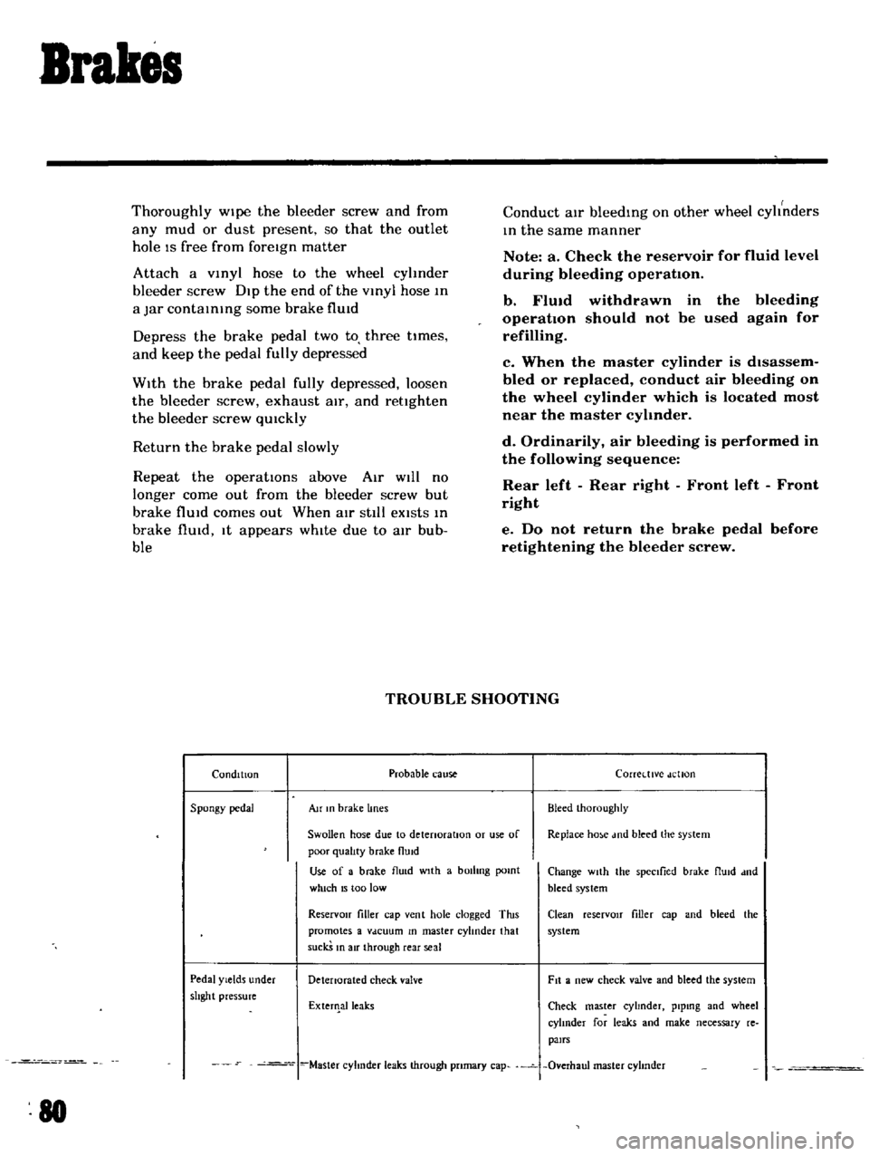
Thoroughly
Wipe
the
bleeder
screw
and
from
any
mud
or
dust
present
so
that
the
outlet
hole
IS
free
from
foreign
matter
Attach
a
VInyl
hose
to
the
wheel
cyhnder
bleeder
screw
Dip
the
end
of
the
VInyl
hose
In
a
Jar
contaInIng
some
brake
flUId
Depress
the
brake
pedal
two
to
three
times
and
keep
the
pedal
fully
depressed
With
the
brake
pedal
fully
depressed
loosen
the
bleeder
screw
exhaust
air
and
rettghten
the
bleeder
screw
qUIckly
Return
the
brake
pedal
slowly
Repeat
the
operatIons
above
Air
WIll
no
longer
come
out
from
the
bleeder
screw
but
brake
flUId
comes
out
When
atr
stIll
eXists
In
brake
flUId
It
appears
whIte
due
to
aIr
bub
ble
Conduct
aIr
bleedIng
on
other
wheel
cyhnders
In
the
same
manner
Note
a
Check
the
reservoir
for
fluid
level
during
bleeding
operation
b
FlUid
withdrawn
in
the
operation
should
not
be
used
refilling
bleeding
again
for
c
When
the
master
cylinder
is
dIsassem
bled
or
replaced
conduct
air
bleeding
on
the
wheel
cylinder
which
is
located
most
near
the
master
cyhnder
d
Ordinarily
air
bleeding
is
performed
in
the
following
sequence
Rear
left
Rear
right
Front
left
Front
right
e
Do
not
return
the
brake
pedal
before
retightening
the
bleeder
screw
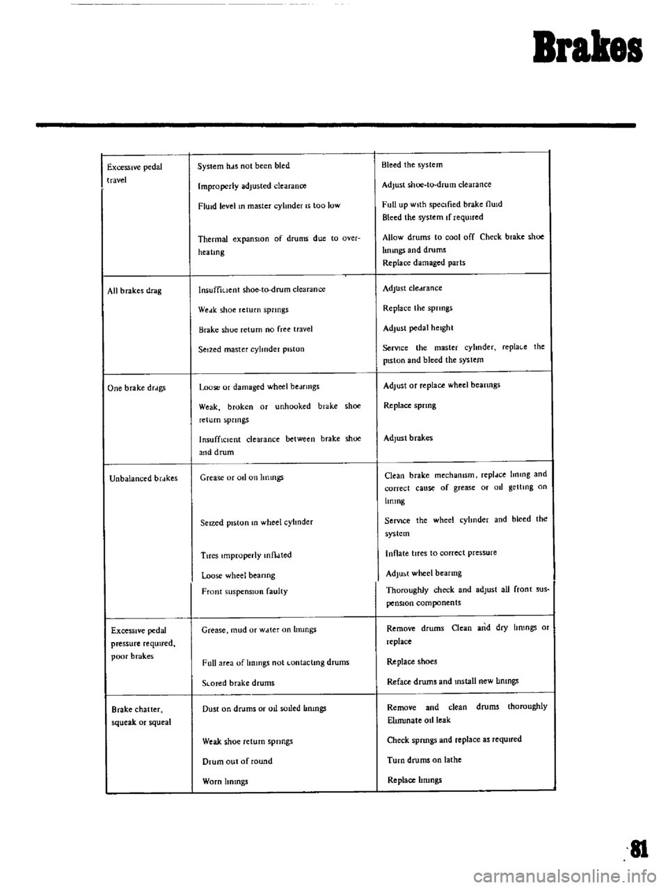
TROUBLE
SHOOTING
Condition
Probable
cause
Corretttve
dellon
Spongy
pedal
Au
In
brake
lines
Bleed
Ihoroughly
Swollen
hose
due
to
detenoratlOn
or
use
of
Replace
ho
e
md
bleed
the
system
poor
qualIty
brake
flUid
Use
of
a
brake
flu
d
wIth
a
bOilIng
pomt
Change
wIth
the
spectlied
brake
flUId
dnd
which
15
too
low
bleed
system
ReservOir
filler
cap
vent
hole
clogged
Tins
Clean
reserVOIr
filler
cap
and
bleed
the
promotes
a
Vdcuum
In
master
cylinder
that
system
suckS
In
air
through
rear
seal
Pedal
Yields
under
Detenorated
check
valve
Fit
a
new
check
valve
and
bleed
the
system
shght
pressure
ExterIlalleaks
Check
master
cyhnder
plpmg
and
wheel
cylInder
for
leaks
and
make
necessary
re
pairs
Master
cyhnder
leaks
through
pnmary
cap
Overhaul
master
cyhnder
80
Page 76 of 136
Brakes
Excessive
pedal
travel
All
b
rakes
drag
One
brake
drdgs
Unbalanced
brdkes
Excessive
pedal
pressure
required
poor
brak
es
Brake
chatter
squeak
or
squeal
System
hds
not
been
bled
Improperly
adjusted
clearance
FlUid
level
In
master
cylinder
IS
too
low
Thermal
expansIOn
of
drums
due
to
Qver
hea
lmg
lnsuffiuent
shoe
to
drum
clearance
Weak
shoe
return
springs
Brake
shoe
return
no
free
travel
Seized
master
cylinder
piston
Loose
or
damaged
wheel
bedfmgs
Weak
broken
or
unhooked
brake
shoe
return
spnngs
InsuffiCient
clearance
between
brake
shoe
and
drum
Grease
or
011
on
hnmgs
Seized
piston
In
wheel
cylInder
Tires
Improperly
mtl
lted
Loose
wheel
bearing
Front
suspension
faulty
Grease
mud
or
w
tter
on
Lmmgs
Full
area
of
Immgs
not
Lontaclmg
drums
SLOTed
brake
drums
Dust
on
drums
or
oIl
soLled
Immgs
Weak
shoe
return
springs
Drum
out
of
round
Worn
Itmngs
Bleed
the
system
Adjust
shoe
to
drum
clearance
Full
up
wIth
specIfied
brake
flUId
Bleed
the
system
If
requIred
Allow
drums
to
cool
off
Check
brake
shoe
lImngs
and
drums
Replace
damaged
parts
Adjust
cledrance
Replace
the
spnngs
Adjust
pedal
height
SerVJce
the
master
cyhnder
repla
e
the
pISton
and
bleed
the
syslem
Adjust
Of
replace
wheel
beanngs
Replace
spnng
Adjust
brakes
Clean
brake
mechamsm
repldce
hnmg
and
correct
cause
of
grease
or
011
getllng
on
Lmmg
SerVIce
the
wheel
cyhnder
and
bleed
the
system
Inflate
tires
to
correct
pressure
Adjust
wheel
bearing
Thoroughly
check
and
adlust
all
front
sus
pensIOn
components
Remove
drums
Clean
and
dry
hrongs
or
replace
Replace
shoes
Reface
drums
and
mstall
new
IImngs
Remove
and
clean
drums
thoroughly
ElImmale
oIl
leak
Check
spnngs
and
replace
as
required
Turn
drums
on
lathe
Replace
hrungs
II
Page 78 of 136
pront
Suspension
Qj
@
@
I
Strut
mounting
Insulator
2
Strut
mounllng
bearing
3
Upper
pnng
o
r
at
4
Oumpu
rubblf
5
DU
tlOVU
6
P
ton
rod
7
F
ool
pring
8
Irut
embly
q
Hub
b
t
mbly
10
5pmdh
II
Ball
JOint
12
Trd
nwu
link
1
J
Tln
lon
rod
14
StJblluLr
15
SU
p
mIOn
mlmbt
r
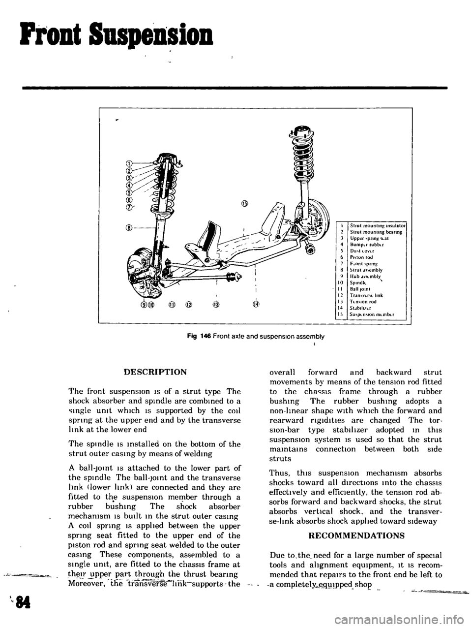
Fig
146
Front
axle
and
suspension
assembly
I
DESCRIPTION
The
front
suspensIOn
IS
of
a
strut
type
The
shock
absorber
and
spIndle
are
combIned
to
a
Ingle
Unit
whIch
IS
supported
by
the
COIl
spnng
at
the
upper
end
and
by
the
transverse
lInk
at
the
lower
end
The
spIndle
IS
Installed
on
the
bottom
of
the
strut
outer
caSIng
by
means
of
weldIng
A
ball
JOInt
IS
attached
to
the
lower
part
of
the
spIndle
The
ball
JOInt
and
the
transverse
lInk
lower
lInk
are
connected
and
they
are
fitted
to
the
suspensIOn
member
through
a
rubber
b
shIng
The
shock
absorber
mechanism
IS
bUIlt
In
the
strut
outer
caSIng
A
COIl
sprIng
IS
apphed
between
the
upper
sprIng
seat
fitted
to
the
upper
end
of
the
piston
rod
and
spring
seat
welded
to
the
outer
caSIng
These
components
assembled
to
a
SIngle
umt
are
fitted
to
the
chaSSIS
frame
at
their
upper
part
through
the
thrust
beanng
M
eover
the
1ransverse
hnk
supports
the
84
overall
forward
and
backward
strut
movements
by
means
of
the
tensIOn
rod
fitted
to
the
cha
sls
frame
through
a
rubber
bushIng
The
rubber
bushIng
adopts
a
non
lInear
shape
WIth
whICh
the
forward
and
rearward
ngldltles
are
changed
The
tor
slOn
bar
type
stabilIzer
adopted
In
thiS
suspensIOn
system
IS
used
so
that
the
strut
maIntaInS
connectIOn
between
both
Side
struts
Thus
thiS
suspensIOn
mechanism
absorbs
shocks
toward
all
directIOns
Into
the
chaSSIS
effectively
and
effiCIently
the
tensIOn
rod
ab
sorbs
forward
and
backward
shocks
the
strut
absorbs
vertical
shock
and
the
transver
se
lInk
absorbs
shock
applIed
toward
SIdeway
RECOMMENDATIONS
Due
to
the
need
for
a
large
number
of
speCial
tools
and
ahgnment
eqUIpment
It
IS
recom
mended
that
repairs
to
the
front
end
be
left
to
a
completely
e
q
pped
shop
Page 91 of 136
Clutch
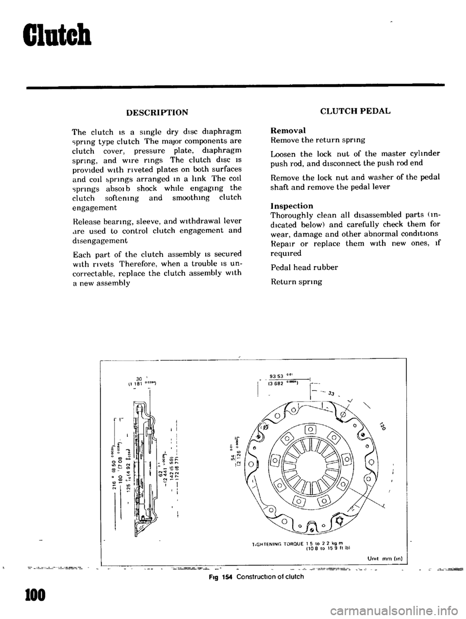
DESCRIPTION
The
clutch
IS
a
sIngle
dry
dIsc
diaphragm
prIng
type
clutch
The
major
components
are
clutch
cover
pressure
plate
diaphragm
sprIng
and
wire
rIngs
The
clutch
diSC
IS
provided
WIth
rIveted
plates
on
both
surfaces
and
cot
bprIngs
arranged
In
a
hnk
The
COIl
prIngs
absOl
b
shock
whIle
engagIng
the
clutch
softemng
and
smoothIng
clutch
engagement
Release
bearIng
sleeve
and
WIthdrawal
lever
dre
used
to
control
clutch
engagement
and
disengagement
Each
part
of
the
clutch
assembly
IS
secured
With
rivets
Therefore
when
a
trouble
IS
un
correctable
replace
the
clutch
assembly
With
a
new
assembly
30
1181
r
I
I
I
I
I
8
1
il
f
0
g
it
l
00
r
O
11
I
N
NN
0
to
lt
lt
ll
l
If
N
O
N
I
I
I
I
FIg
154
Construction
of
clutch
100
CLUTCH
PEDAL
Removal
Remove
the
return
sprmg
Loosen
the
lock
nut
of
the
master
cyhnder
push
rod
and
disconnect
the
push
rod
end
Remove
the
lock
nut
and
washer
of
the
pedal
shaft
and
remove
the
pedal
lever
Inspection
Thoroughly
clean
all
disassembled
parts
m
dlcated
below
and
carefully
check
them
for
wear
damage
and
other
abnormal
conditions
RepaIr
or
replace
them
With
new
ones
If
reqUIred
Pedal
head
rubber
Return
sprIng
9353
3682
00004
lIGHTENING
TORQUE
1
5
to
2
2
kg
m
108
to
159ft
lbl
UOIt
mm
Inl
Page 93 of 136
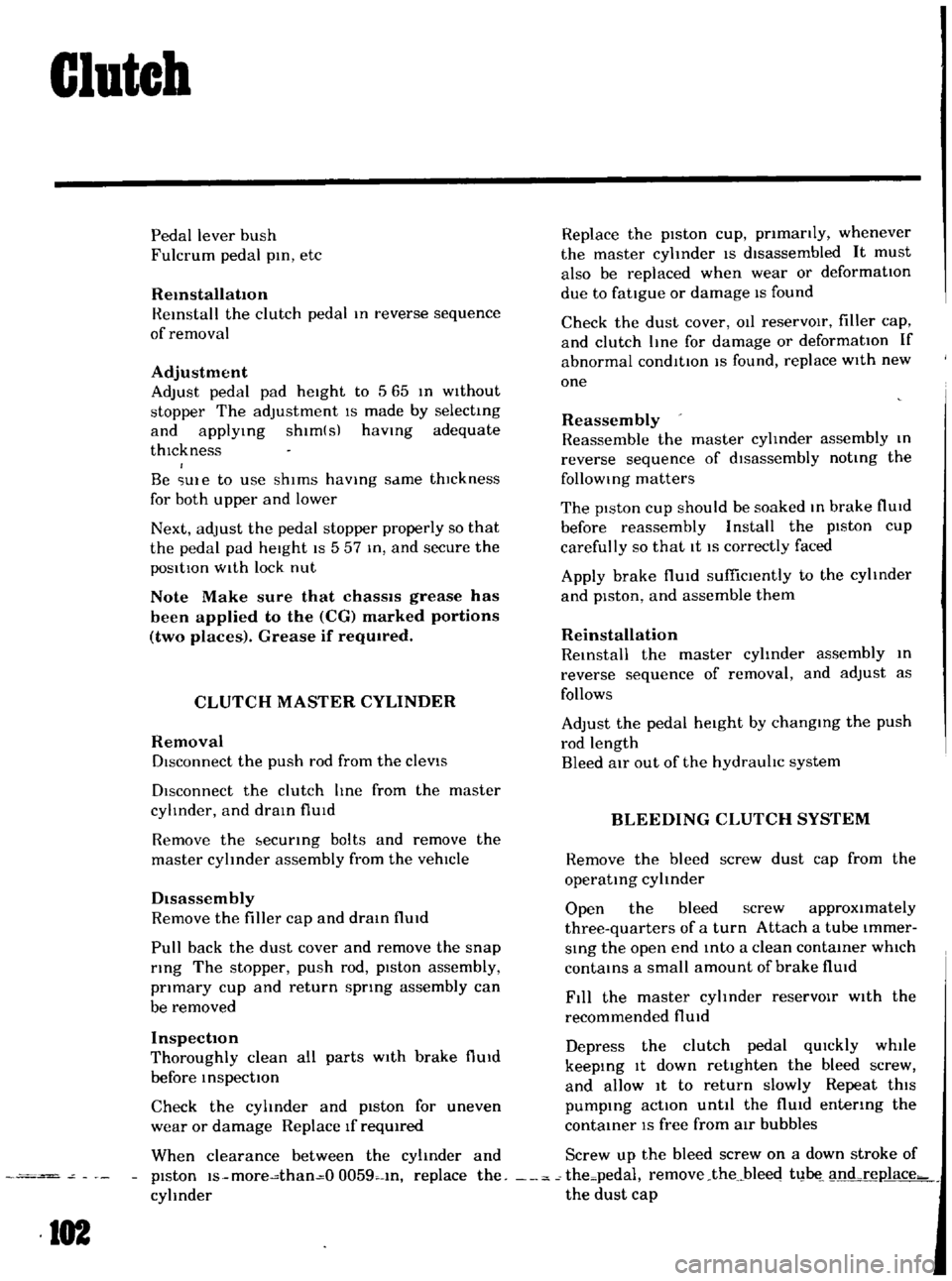
Clutch
Pedal
lever
bush
Fulcrum
pedal
pIn
etc
Remstallation
Reinstall
the
clutch
pedal
In
reverse
sequence
of
removal
Adjustment
Adjust
pedal
pad
heIght
to
565
In
Without
stopper
The
adjustment
IS
made
by
selectmg
and
applYIng
shlm
s
haVing
adequate
thIckness
Be
Ule
to
use
shIms
haVIng
same
thIckness
for
both
upper
and
lower
Next
adjust
the
pedal
stopper
properly
so
that
the
pedal
pad
height
IS
557
In
and
secure
the
pOSitIOn
WIth
lock
nut
Note
Make
sure
that
chaSSIS
grease
has
been
applied
to
the
CG
marked
portions
two
places
Grease
if
reqUired
CLUTCH
MASTER
CYLINDER
Removal
DIsconnect
the
push
rod
from
the
cleVIS
DIsconnect
the
clutch
lIne
from
the
master
cylinder
and
draIn
flUid
Remove
the
ecunng
bolts
and
remove
the
master
cyhnder
assembly
from
the
vehIcle
DIsassembly
Remove
the
filler
cap
and
draIn
flUId
Pull
back
the
dust
cover
and
remove
the
snap
rIng
The
stopper
push
rod
pIston
assembly
pnmary
cup
and
return
sptlng
assembly
can
be
removed
Inspection
Thoroughly
clean
all
parts
With
brake
flUId
before
InspectIOn
Check
the
cyhnder
and
piston
for
uneven
wear
or
damage
Replace
If
required
When
clearance
between
the
cylinder
and
pIston
IS
more
than
O
0059
In
replace
the
cyhnder
102
Replace
the
pIston
cup
pnmanly
whenever
the
master
cyhnder
IS
dIsassembled
It
must
also
be
replaced
when
wear
or
deformatIOn
due
to
fatIgue
or
damage
IS
found
Check
the
dust
cover
OIl
reservOIr
filler
cap
and
clutch
lIne
for
damage
or
deformatIOn
If
abnormal
condItIOn
IS
found
replace
With
new
one
Reassembly
Reassemble
the
master
cylInder
assembly
In
reverse
sequence
of
dIsassembly
notIng
the
follOWIng
matters
The
pIston
cup
should
be
soaked
In
brake
flUId
before
reassembly
Install
the
pIston
cup
carefully
so
that
It
IS
correctly
faced
Apply
brake
flUId
suffiCIently
to
the
cyhnder
and
pIston
and
assemble
them
Reinstallation
ReInstall
the
master
cyhnder
assembly
In
reverse
sequence
of
removal
and
adjust
as
follows
Adjust
the
pedal
heIght
by
changmg
the
push
rod
length
Bleed
air
out
of
the
hydrauhc
system
BLEEDING
CLUTCH
SYSTEM
Remove
the
bleed
screw
dust
cap
from
the
operatIng
cyhnder
Open
the
bleed
screw
approximately
three
quarters
of
a
turn
Attach
a
tube
Immer
SIng
the
open
end
mto
a
clean
contaIner
which
contaInS
a
small
amount
of
brake
flUId
Fill
the
master
cyhnder
reservOIr
With
the
recommended
flUId
Depress
the
clutch
pedal
qUIckly
while
keepIng
It
down
retighten
the
bleed
screw
and
allow
It
to
return
slowly
Repeat
thiS
pumpIng
actIOn
unttl
the
flUId
entenng
the
contaIner
IS
free
from
air
bubbles
Screw
up
the
bleed
screw
on
a
down
stroke
of
the
pedal
remove
the
bleec
t1
1
nd
rel1lace
the
dust
cap
Page 97 of 136
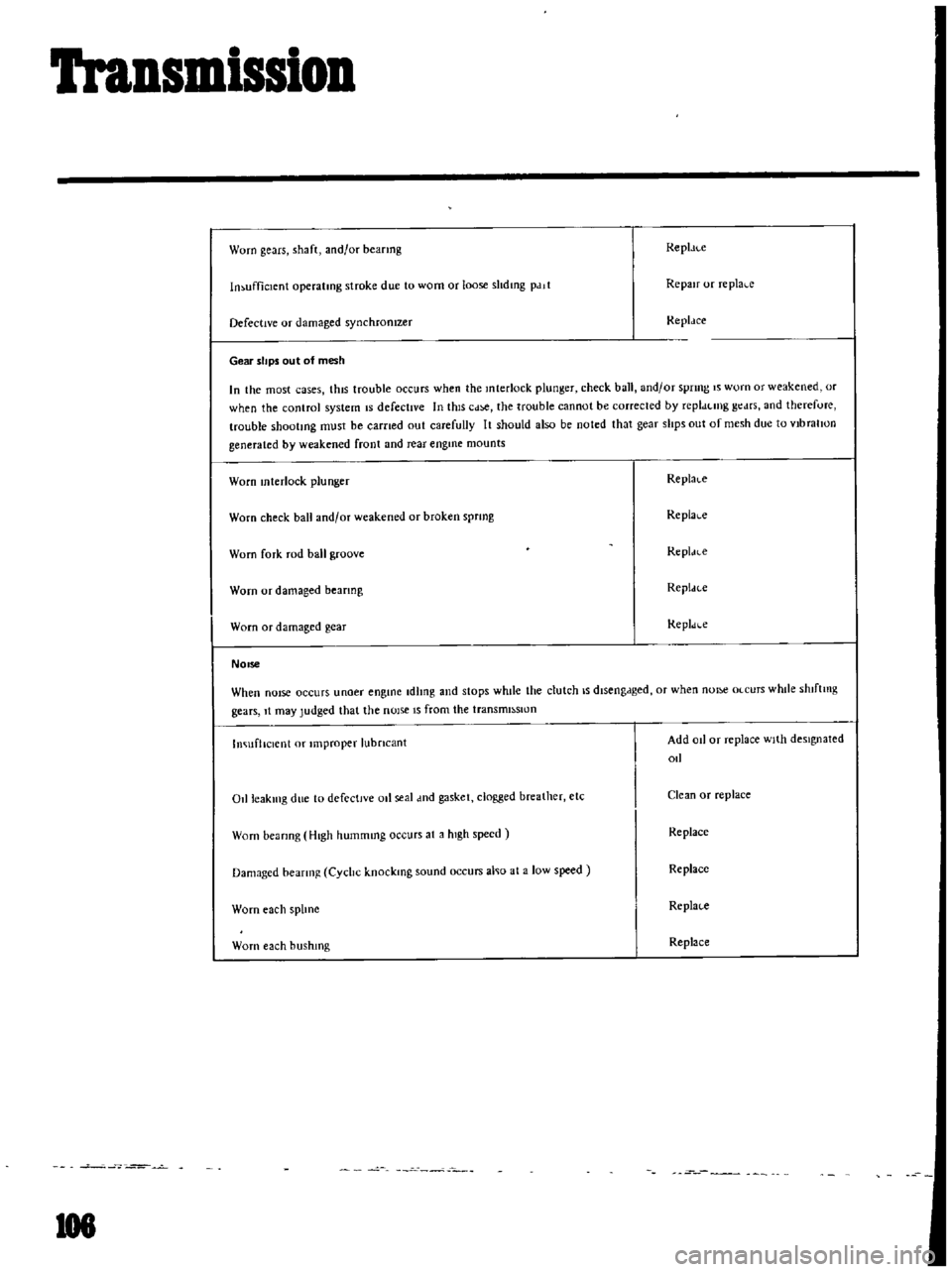
Transmission
Worn
gears
shaft
and
or
heanng
Repl
ll
c
In
ufficlcnt
operatmg
stroke
due
to
worn
or
loose
shdmg
pdll
Repair
or
replal
c
Defective
or
damaged
synchronIzer
Replace
Gear
slips
out
of
mesh
In
the
most
cases
thiS
trouble
occurs
when
the
Interlock
plunger
check
ball
and
or
spnng
IS
worn
or
weakened
or
when
the
control
system
IS
defectIve
In
thiS
Cd
the
trouble
cannot
be
corrected
by
repldtlllg
gt
drs
and
therefore
trouble
shootmg
must
be
earned
out
carefully
It
should
also
be
noted
that
gear
slips
out
of
mesh
due
to
vlbralIon
generated
by
weakened
front
and
rear
engme
mounts
Worn
mterlock
plunger
Replal
c
Worn
check
hall
and
or
weakened
or
broken
sprmg
Replal
c
Worn
fork
rod
ball
groove
RepI
H
e
Worn
or
damaged
beanng
Repldce
Worn
or
damaged
gear
Repldl
c
NOise
When
nOIse
occurs
unoer
engine
Idling
and
stops
whde
the
clutch
IS
dlseng
lged
or
when
nOI
Olcurs
while
shlftmg
gears
It
may
Judged
that
the
nOIse
IS
from
the
tranSmll
lSIUn
Ino
ufllclenl
or
1mproper
lubncant
Add
od
or
replace
With
deSignated
oIl
Ollleaklllg
due
to
defectIve
011
seal
md
gasket
clogged
breather
etc
Clean
or
replace
Worn
beanng
High
hummmg
occurs
at
a
high
speed
Replace
Damaged
beanng
Cychc
knockmg
sound
occurs
alllo
at
a
low
speed
Replace
Worn
each
sphne
Replace
Worn
each
hushmg
Replace
108
Page 98 of 136
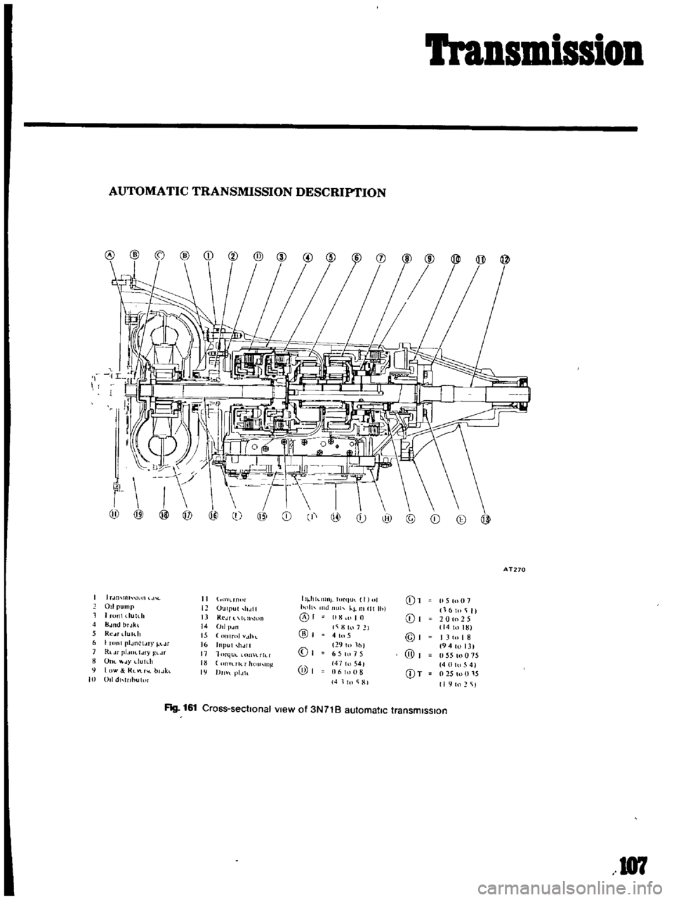
Transmission
AUTOMATIC
TRANSMISSION
DESCRIPTION
I
Ii
9
0
@
@
AT270
1
U
lllll
II
O
l
rn
lr
II
hkl1lllj
ItlrllUl
I
II
01
15
tu
07
011
pump
12
OUllJllt
holtl
h
llt
Ih
kl
Illllt
Ihl
16
to
i
II
1
1
runl
dUlth
13
Kl
JT
llhlOIl
01
10
01
20
to
2
5
4
B
H1d
brJkl
14
011
p
Jll
l
i
H
hl
7
14toHn
5
Re
u
du
h
15
lIT01
tlvt
@
41u5
@I
I
310
I
8
6
I
ronl
plJllctJry
lJr
16
Input
11
111
0
29101fll
194
013
1
Rldr
pIJIJC
IJ
ry
j
l
Lr
11
1
m
lu
n
lIh
T
6
5
tn
15
@
055toO
5
OIll
JYdutdt
rllT
11
l1
11l
@I
147
to
541
40
0
5
4
9
I
lW
RlVlr
l
bl
Jkl
19
Dm
l
plJh
16
III
8
CDT
l
2S
to
U
l
S
10
011
dl
nbulm
4
11n
i
HI
I
I
to
2
iJ
Flg
161
Cross
sectIonal
view
of
3N71B
automatic
transmIssIon
107
Page 116 of 136
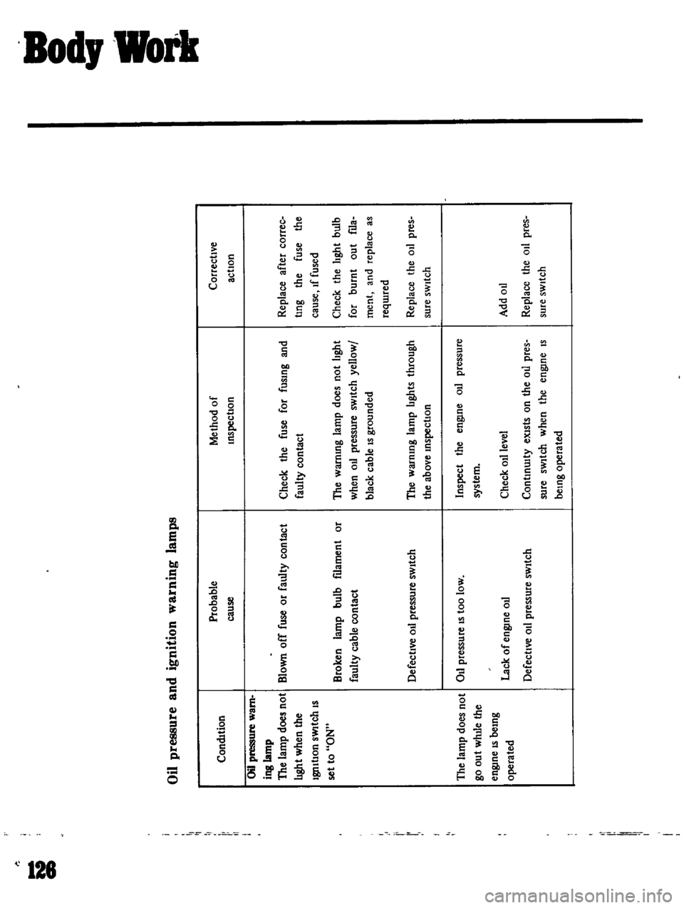
II
II
II
II
Oil
pressure
and
ignition
warning
lamps
condition
Oil
pressure
warn
ing
lamp
The
amp
does
not
hght
when
the
19I1ItlOn
sWItch
IS
set
to
ON
II
I
Ptobable
cause
Blown
off
fuse
or
faulty
contact
Broken
lamp
bulb
filament
or
faulty
cable
contact
Defective
oil
pressure
swltch
The
lamp
does
not
Oil
pressure
IS
toO
loW
go
out
wlule
the
engtne
IS
being
operated
Lack
of
engine
oil
Defective
Oil
pressure
sWitch
Il
MethOd
of
tnSpeCtlOn
Check
the
fuse
for
fusing
and
faulty
contact
The
warntng
lamP
does
not
bght
when
oil
pressure
sWitch
yelloW
I
black
cable
15
grounded
The
warntng
lamp
bghts
through
the
above
tnspectlOn
inspect
the
engine
ou
pressure
system
Check
011
level
ConttnUlty
eXists
on
the
oil
pres
sure
sWltch
when
the
engine
IS
belng
operated
o
a
t
a
CorrectIVe
action
Replace
after
COffee
tlng
the
fuse
the
cause
lf
fused
Check
the
hght
bulb
for
burnt
out
fila
ment
and
replace
as
reqUIred
Replace
the
011
pres
Sure
sWitch
Add
oil
Replace
the
01
pres
sure
sWitch