1969 DATSUN B110 length
[x] Cancel search: lengthPage 19 of 136
IBglne
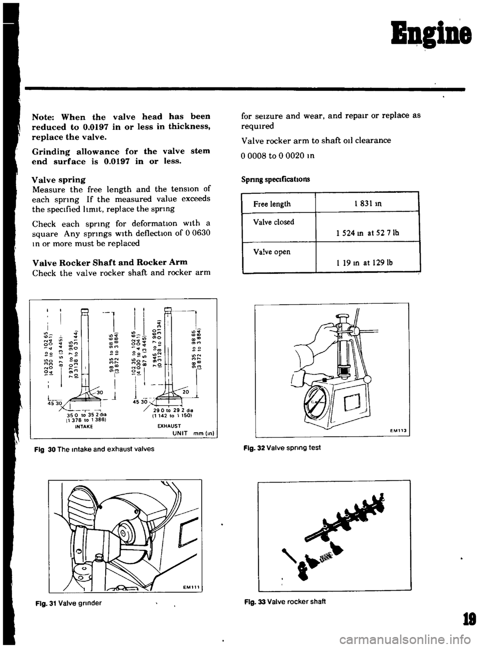
Note
When
the
valve
head
has
been
reduced
to
0
0197
in
or
less
in
thickness
replace
the
valve
Grinding
allowance
for
the
valve
stem
end
surface
is
0
0197
in
or
less
Valve
spring
Measure
the
free
length
and
the
tensIOn
of
each
spnng
If
the
measured
value
exceeds
the
specIfied
hmlt
replace
the
sprlllg
Check
each
spnng
for
deformatIOn
with
a
square
Any
sprmgs
w1th
deflectIOn
of
0
0630
III
or
more
must
be
replaced
Valve
Rocker
Shaft
and
Rocker
Arm
Check
the
valve
rocker
shaft
and
rocker
arm
1
N
in
00
9E
22
N
o
NO
I
I
I
I
1
I
I
Ll
gE
N
cno
CX
co
00
r
o
171M
OtM
Be
22
Bo
l
N
11
lit
l
o
cnM
l
Q
1
45
30
290
to
29
2
die
1142
to
1
1501
N
I
350
to
35
2dla
1
378
to
1386
INTAKE
EXHAUST
UNIT
mm
lnl
Fig
30
The
Intake
and
exhaust
valves
Fig
31
Valve
grinder
for
seizure
and
wear
and
repair
or
replace
as
required
Valve
rocker
arm
to
shaft
011
clearance
o
0008
to
0
0020
III
Spnng
specIficatIOns
Free
length
1
831
In
Valve
closed
1
524
In
at
52
7
Ib
Valve
open
I
19
III
at
1291b
EM
J
Fig
32
Valve
spring
test
Fig
33
Valve
rocker
shaft
lB
Page 23 of 136
Square
rmg
m
bore
by
pushing
It
mto
pos1t1on
wIth
the
head
piston
Measure
gap
between
ends
of
rmg
with
feeler
gauge
Gap
should
be
as
hsted
above
Note
a
When
the
piston
ring
only
is
to
be
replaced
without
the
cylinder
bore
bemg
corrected
measure
gap
at
the
bottom
of
the
cylinder
where
the
wear
is
minor
b
Overs1ze
piston
rings
are
avaIlable
for
service
50
100
150
oversize
Measure
the
piston
pm
hole
m
relation
to
the
outer
dIameter
of
the
pm
If
wear
exceeds
the
hmlt
replace
such
piston
pm
together
with
the
pIston
on
whIch
It
IS
mstalled
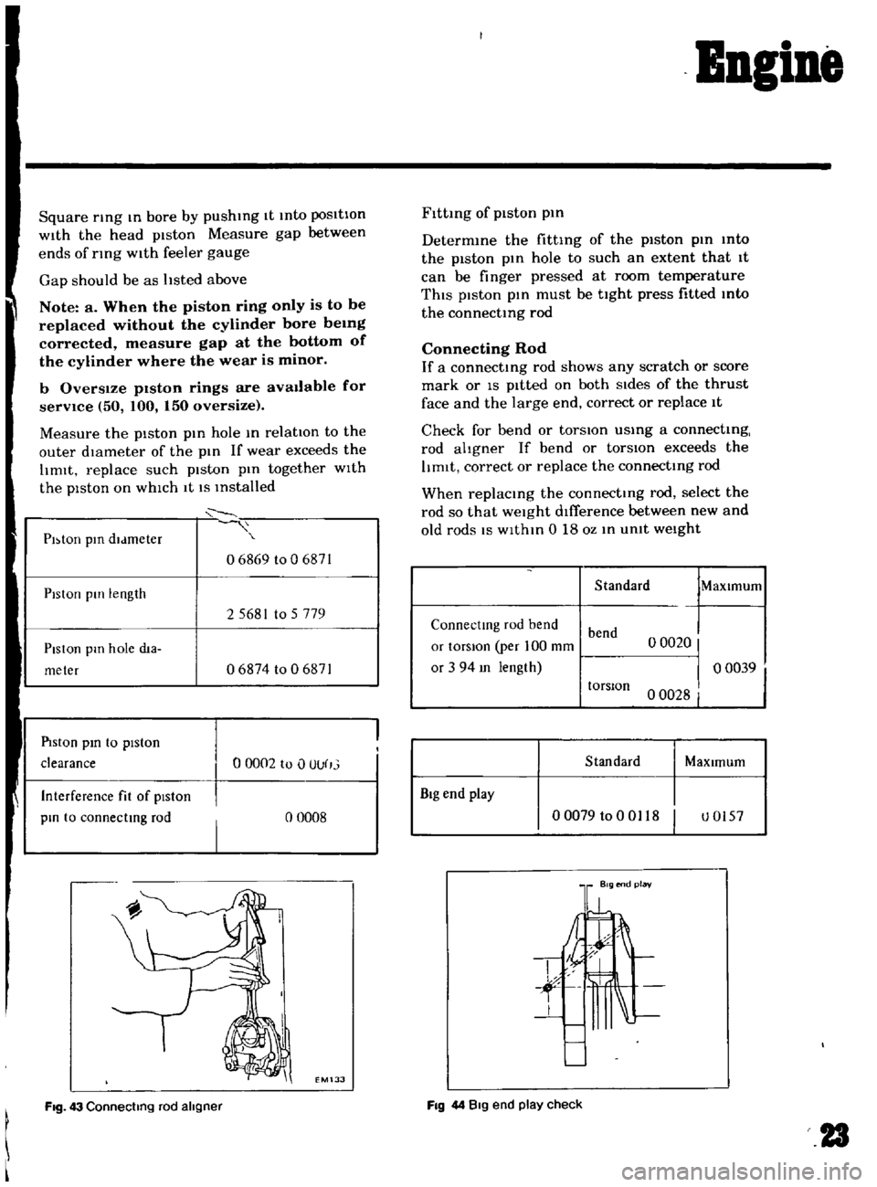
PI
ton
pill
dldmeter
06869
to
06871
PIston
pill
length
25681
to
5779
Piston
pm
hole
dta
meter
06874
to
0
6871
PIston
pm
to
piston
clearance
00002
to
OOUr
j
Interference
fit
of
piston
pm
to
connectmg
rod
o
0008
EM133
FIg
43
Connecting
rod
ahgner
Bngine
Flttmg
of
piston
pm
Determme
the
fittmg
of
the
piston
pm
mto
the
piston
pm
hole
to
such
an
extent
that
1t
can
be
finger
pressed
at
room
temperature
ThIS
piston
pm
rnust
be
tight
press
fitted
mto
the
connectmg
rod
Connecting
Rod
If
a
connectmg
rod
shows
any
scratch
or
score
mark
or
IS
pitted
on
both
Sides
of
the
thrust
face
and
the
large
end
correct
or
replace
It
Check
for
bend
or
torsIOn
usmg
a
connectmg
rod
ahgner
If
bend
or
torsIOn
exceeds
the
hmlt
correct
or
replace
the
connectmg
rod
When
replacing
the
connectmg
rod
select
the
rod
so
that
weight
difference
between
new
and
old
rods
IS
wlthm
0
18
oz
m
umt
weIght
Standard
MaXimum
Connectmg
rod
bend
bend
or
tOrsIon
per
100
mm
o
0020
or
3
94
m
length
o
00391
torsIOn
o
0028
I
Standard
MaXImum
BIg
end
play
00079
to
0
0118
I
U0157
FIg
44
Big
end
play
check
23
Page 33 of 136
ApplYing
a
sUItable
wrench
or
spanner
loosen
off
the
regulator
valve
Note
a
When
placmg
the
valve
m
a
VIse
use
extreme
care
not
to
dIstort
the
pump
body
and
cover
in
the
jaws
b
Do
not
pull
out
the
drive
shaft
pin
securing
the
drIven
shaft
and
inner
rotor
The
shaft
is
press
fitted
to
the
rotor
with
the
pin
calked
Inspection
and
Repair
Clean
the
dIsassembled
parts
with
cleamng
solvent
and
Inspect
for
defects
Inspect
the
dnve
rotor
shaft
for
excessIve
wear
and
scores
and
check
the
follOWing
clearances
SIde
clearance
between
outer
and
Inner
rotors
0
0047
In
or
below
Tip
clearance
00016
to
0
0047
In
Clearance
between
outer
rotor
and
body
o
0059
to
0
0083
In
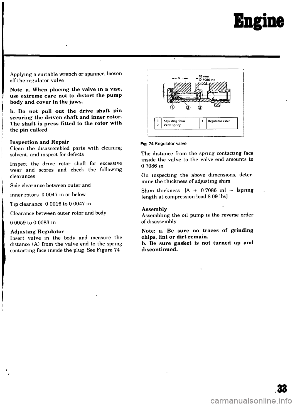
AdjustIng
Regulator
Insert
valve
In
the
body
and
measure
the
dIstance
A
from
the
valve
end
to
the
spnng
contacting
face
inside
the
plug
See
Figure
74
Bngine
1
Adjusting
h
rn
rJ
Regul
m
Valve
spnn
FIg
74
Regulator
valve
The
distance
from
the
spring
contacting
face
inSide
the
valve
to
the
valve
end
amounts
to
o
7086
m
On
inspecting
the
above
dlmenslOns
deter
mine
the
thickness
of
adjusting
shim
ShIm
thickness
A
0
7086
In
spring
length
at
compresslOn
load
809
lbs
Assembly
Assembhng
the
011
pump
IS
the
reverse
order
of
disassembly
Note
a
Be
sure
no
traces
of
grinding
chips
lint
or
dirt
remain
b
Be
sure
gasket
is
not
turned
up
and
dIscontinued
33
Page 70 of 136
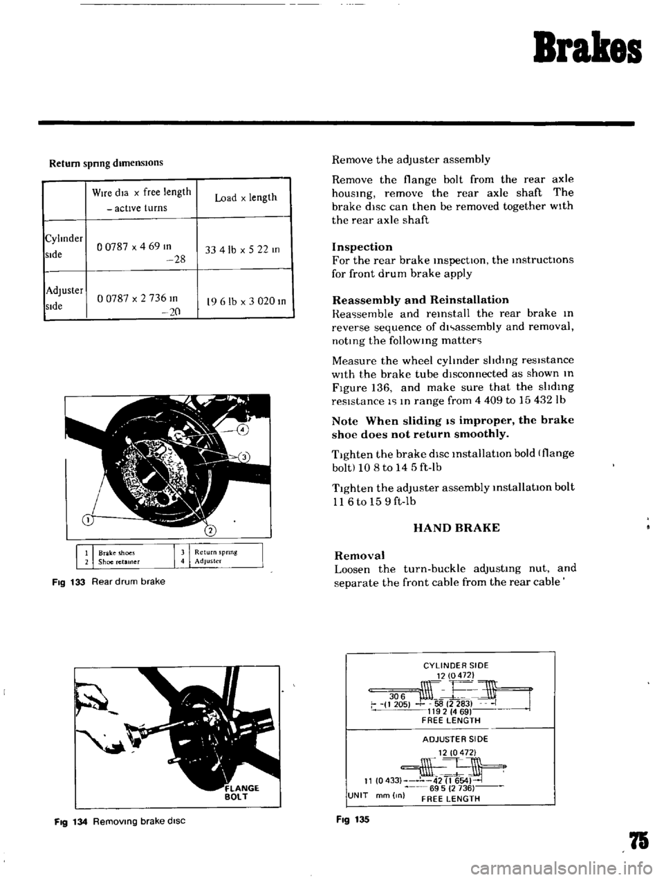
Brakes
Return
spnng
dimensIOns
Wire
dla
x
free
length
Load
x
length
actIve
turns
Cylmder
o
0787
x
4
69
III
sIde
33
4lb
x
5
22
m
28
Adjuster
00787
x
2
736
m
sIde
19
6
lb
x
3
020
III
20
1
Brake
moes
2
Shoe
retamer
Fig
133
Rear
drum
brake
Fig
134
Removmg
brake
disc
Remove
the
adjuster
assembly
Remove
the
flange
bolt
from
the
rear
axle
housing
remove
the
rear
axle
shaft
The
brake
disc
can
then
be
removed
together
wIth
the
rear
axle
shaft
Inspection
For
the
rear
brake
inspectIOn
the
instructIOns
for
front
drum
brake
apply
Reassembly
and
Reinstallation
Rea
semble
and
reinstall
the
rear
brake
In
reverse
sequence
of
dl
assembly
and
removal
noting
the
follOWing
matter
Measure
the
wheel
cylinder
shdlng
resistance
With
the
brake
tube
dIsconnected
as
shown
In
Figure
136
and
make
sure
that
the
slIding
resIstance
1
In
range
from
4
409
to
15432
Ib
Note
When
sliding
IS
improper
the
brake
shoe
does
not
return
smoothly
Tighten
the
brake
diSC
installatIOn
bold
flange
bolt
10
8
to
14
5
ft
Ib
T1ghten
the
adjuster
assembly
installatIOn
bolt
116to
159ft
Ib
HAND
BRAKE
Removal
Loosen
the
turn
buckle
adjusting
nut
and
separate
the
front
cable
from
the
rear
cable
CYLINDER
SIDE
306
j
E
i
1
205
58
2
283
J
1192
469
FREE
LENGTH
ADJUSTE
R
51
DE
12
0472
2
11
0433
42
1654
69
5
2
736
UNIT
mm
0
FREE
LENGTH
Fig
135
75
Page 93 of 136
Clutch
Pedal
lever
bush
Fulcrum
pedal
pIn
etc
Remstallation
Reinstall
the
clutch
pedal
In
reverse
sequence
of
removal
Adjustment
Adjust
pedal
pad
heIght
to
565
In
Without
stopper
The
adjustment
IS
made
by
selectmg
and
applYIng
shlm
s
haVing
adequate
thIckness
Be
Ule
to
use
shIms
haVIng
same
thIckness
for
both
upper
and
lower
Next
adjust
the
pedal
stopper
properly
so
that
the
pedal
pad
height
IS
557
In
and
secure
the
pOSitIOn
WIth
lock
nut
Note
Make
sure
that
chaSSIS
grease
has
been
applied
to
the
CG
marked
portions
two
places
Grease
if
reqUired
CLUTCH
MASTER
CYLINDER
Removal
DIsconnect
the
push
rod
from
the
cleVIS
DIsconnect
the
clutch
lIne
from
the
master
cylinder
and
draIn
flUid
Remove
the
ecunng
bolts
and
remove
the
master
cyhnder
assembly
from
the
vehIcle
DIsassembly
Remove
the
filler
cap
and
draIn
flUId
Pull
back
the
dust
cover
and
remove
the
snap
rIng
The
stopper
push
rod
pIston
assembly
pnmary
cup
and
return
sptlng
assembly
can
be
removed
Inspection
Thoroughly
clean
all
parts
With
brake
flUId
before
InspectIOn
Check
the
cyhnder
and
piston
for
uneven
wear
or
damage
Replace
If
required
When
clearance
between
the
cylinder
and
pIston
IS
more
than
O
0059
In
replace
the
cyhnder
102
Replace
the
pIston
cup
pnmanly
whenever
the
master
cyhnder
IS
dIsassembled
It
must
also
be
replaced
when
wear
or
deformatIOn
due
to
fatIgue
or
damage
IS
found
Check
the
dust
cover
OIl
reservOIr
filler
cap
and
clutch
lIne
for
damage
or
deformatIOn
If
abnormal
condItIOn
IS
found
replace
With
new
one
Reassembly
Reassemble
the
master
cylInder
assembly
In
reverse
sequence
of
dIsassembly
notIng
the
follOWIng
matters
The
pIston
cup
should
be
soaked
In
brake
flUId
before
reassembly
Install
the
pIston
cup
carefully
so
that
It
IS
correctly
faced
Apply
brake
flUId
suffiCIently
to
the
cyhnder
and
pIston
and
assemble
them
Reinstallation
ReInstall
the
master
cyhnder
assembly
In
reverse
sequence
of
removal
and
adjust
as
follows
Adjust
the
pedal
heIght
by
changmg
the
push
rod
length
Bleed
air
out
of
the
hydrauhc
system
BLEEDING
CLUTCH
SYSTEM
Remove
the
bleed
screw
dust
cap
from
the
operatIng
cyhnder
Open
the
bleed
screw
approximately
three
quarters
of
a
turn
Attach
a
tube
Immer
SIng
the
open
end
mto
a
clean
contaIner
which
contaInS
a
small
amount
of
brake
flUId
Fill
the
master
cyhnder
reservOIr
With
the
recommended
flUId
Depress
the
clutch
pedal
qUIckly
while
keepIng
It
down
retighten
the
bleed
screw
and
allow
It
to
return
slowly
Repeat
thiS
pumpIng
actIOn
unttl
the
flUId
entenng
the
contaIner
IS
free
from
air
bubbles
Screw
up
the
bleed
screw
on
a
down
stroke
of
the
pedal
remove
the
bleec
t1
1
nd
rel1lace
the
dust
cap
Page 103 of 136
Bod
Work
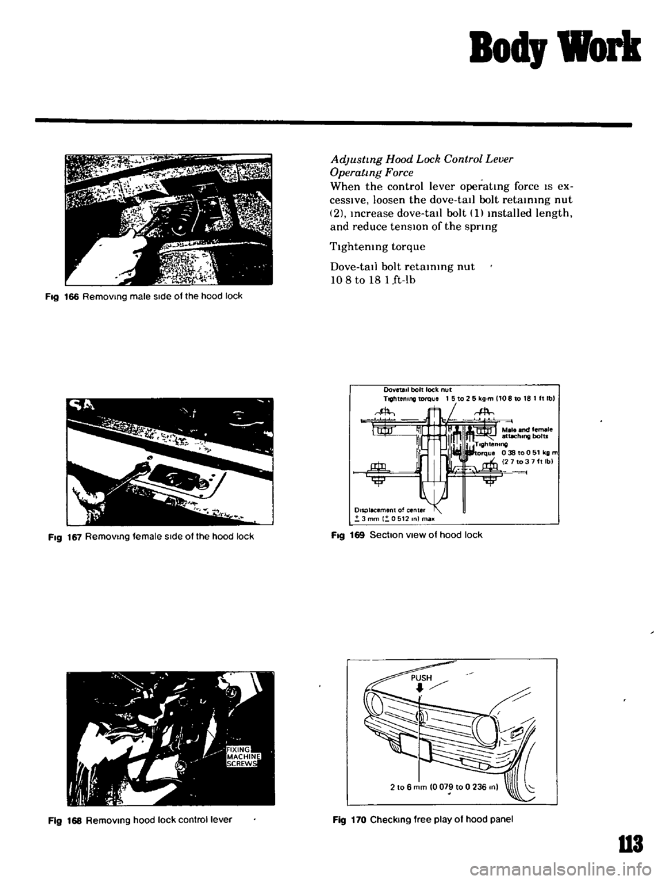
Adjusting
Hood
Lock
Control
Lever
Operating
Force
When
the
control
lever
operatmg
force
IS
ex
ceSSlve
loosen
the
dove
tail
bolt
retammg
nut
2
Increase
dove
tall
bolt
1
mstalled
length
and
reduce
tensIOn
of
the
spring
Tightening
torque
Dove
tall
bolt
retaining
nut
108
to
18
1
ft
lb
Fig
166
Removing
male
Side
of
the
hood
lock
DovetaIl
bolt
lock
nut
Ttghtenlllg
torque
1
5
to
2
5
kg
m
1108
to
18
1
It
Ib
FIg
167
Removing
female
Side
ofthe
hood
lock
FIg
169
Section
view
of
hood
lock
2
10
6
mm
0079
10
0
236
on
Fig
168
Removing
hood
lock
control
lever
Fig
170
Checking
free
play
of
hood
panel
U3
Page 104 of 136
Bod
Work
J
G
3
1
7
iJ
0
t
Fig
171
Adjusting
dove
tall
boll
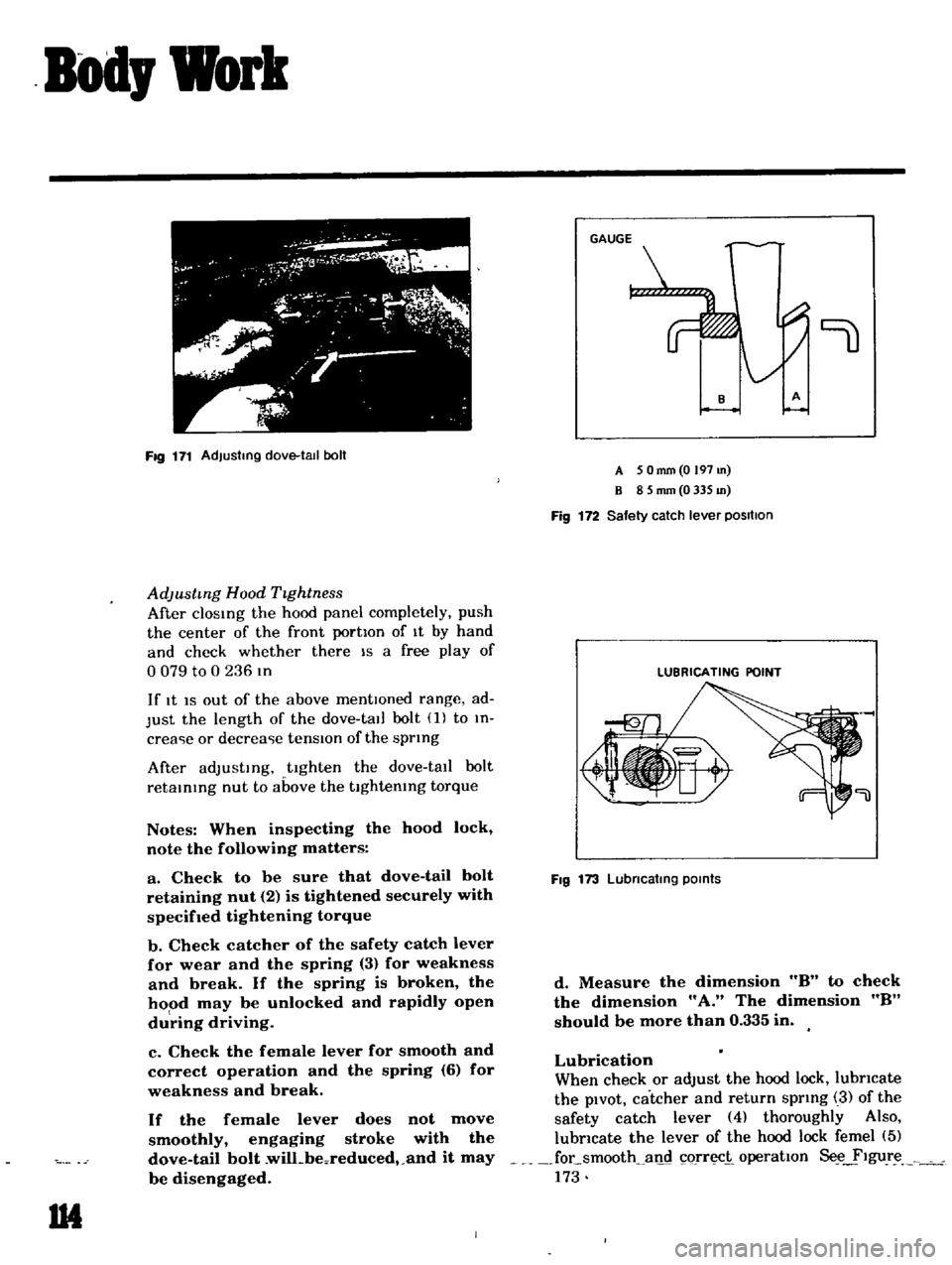
AdJustmg
Hood
TIghtness
After
clOSIng
the
hood
panel
completely
push
the
center
of
the
front
portIon
of
It
by
hand
and
check
whether
there
IS
a
free
play
of
o
079
to
0
236
In
If
It
IS
out
of
the
above
mentIOned
range
ad
Just
the
length
of
the
dove
tall
bolt
1
to
In
crea
ie
or
decrea
ie
tensIOn
of
the
sprIng
After
adJustIng
tighten
the
dove
tall
bolt
retaInIng
nut
to
above
the
tIghtenIng
torque
Notes
When
inspecting
the
hood
lock
note
the
following
matters
a
Check
to
be
sure
that
dove
tail
bolt
retaining
nut
2
is
tightened
securely
with
specifIed
tightening
torque
b
Check
catcher
of
the
safety
catch
lever
for
wear
and
the
spring
3
for
weakness
and
break
If
the
spring
is
broken
the
hood
may
be
unlocked
and
rapidly
open
du
ring
driving
c
Check
the
female
lever
for
smooth
and
correct
operation
and
the
spring
6
for
weakness
and
break
If
the
female
lever
does
not
move
smoothly
engaging
stroke
with
the
dove
tail
bolt
wilLbeoreduced
and
it
may
be
disengaged
1M
9
A
5
Omm
O
197
m
B
8
5
mm
0
335
m
Fig
172
Safety
catch
lever
positIOn
LUBRICATING
POINT
Fig
173
Lubncatlng
POints
d
Measure
the
dimension
8
to
check
the
dimension
A
The
dimension
8
should
be
more
than
0
335
in
Lubrication
When
check
or
adjust
the
hood
lock
lubricate
the
pIvOt
catcher
and
return
sprIng
3
of
the
safety
catch
lever
4
thoroughly
Also
lubricate
the
lever
of
the
hood
lock
femel
5
focsmooth
all
c1
orr
i
operatIon
Se
ylgur
173
Page 120 of 136
Specifications
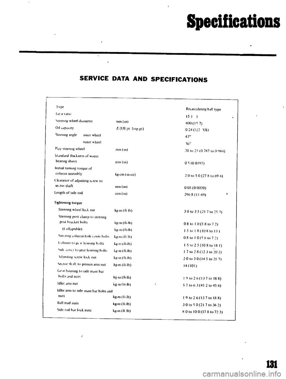
SERVICE
DATA
AND
SPECIFICATIONS
1
vpc
RCl
n
ulatlllg
bdll
type
ClrrJtm
Ieertng
wheel
dldl1lCler
Od
JpJuty
iteenng
angle
IImer
wheel
outer
heel
PIdY
Ieermg
wheel
tJJ
d
ud
thl
kness
of
worm
beaTIng
shulls
hllttal
turnmg
torque
of
column
assembly
le
Hance
uf
ddJustmg
SLrew
to
sedor
shaft
Length
of
side
rod
TlghteolOg
torque
Steenng
wheellol
k
nul
Steenng
po
t
d
unp
to
steermg
pO
1
hr
H
lct
holts
llIlJp
ihlc
C
lrtng
llImn
hole
over
hnlt
IllImn
10
L
If
hOUI
IIl
holts
tdt
t
f
III
ge
lf
hou
lIl
holh
dlu
m
l
rew
m
nut
edM
h
If
I
10
plllllJIl
drill
nut
If
hOll
lI1g
In
Side
I1MIIl
bar
holt
Jlld
nut
Idler
dflll
nul
Idler
arm
to
stde
l1lJlO
bar
bolts
Jnd
nuts
B
III
stud
nuts
51dc
rod
hJf
IOl
k
nuts
mm
m
15
I
400
7
024
1
211
L
US
pI
Imp
pt
43
1
16
111111
111
20
to
2
10
7X7
to
0
JX4
mm
m
OS
0
0197
kg
cm
lIl
oz
2
0
to
5
0
27
X
10
69
4
mm
m
005
0
0020
296
8
1169
nun
Ill
kg
Ill
ft
Ihl
3
0
10
3
5
I
7
10
2
S
1
kg
m
ft
Ih
kg
Ill
ft
Ih
kg
Ill
I
ft
Ih
kg
Ill
ft
Ib
kg
Ill
ft
Ih
kg
m
ft
Ih
kg
m
ft
Ih
08
to
I
0
5
8
107
15
to
18
108
to
13
I
o
8
10
I
0
S
X
to
7
I
1
5
to
2
5
10810
18
I
7
10
2
8
12
3
10
20
2
201030
14510217
14
101
kg
Ill
ft
Ib
kg
mltt
Ih
I
9
to
2
6
13
7
to
18
8
5
7
106
3
4
2
1045
6
kg
m
ft
Ib
kg
m
ft
Ib
kg
Ill
ft
Ih
191026
13710188
30
to
0
21
7
to
36
2
XOlo
100
57810723
I3l