Page 96 of 252

CHAPTER
NINE
ENGINE
ELECTRICAL
SYSTEM
The
electrIcal
system
has
undergone
slIght
yearly
changes
the
most
SignIficant
being
ill
the
distrIbutor
Some
models
have
a
smgle
contact
pomt
whIle
others
have
a
dual
pomt
system
De
talls
are
covered
m
the
dIstrIbutor
sectlon
The
electrIcal
system
IS
a
12
volt
negatIve
type
OPERATION
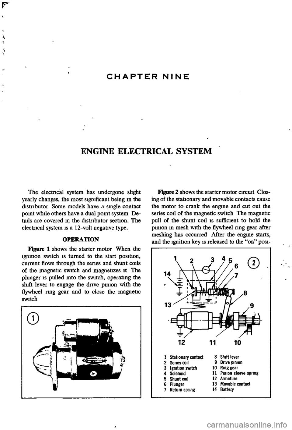
Figure
1
shows
the
starter
motor
When
the
Ignltlon
sWItch
IS
turned
to
the
start
pOSItIon
current
flows
through
the
senes
and
shunt
colis
of
the
magnetIc
SWitch
and
magnetizes
It
The
plunger
IS
pulled
mto
the
sWItch
operatlng
the
shIft
lever
to
engage
the
dnve
pmlon
with
the
flywheel
rmg
gear
and
to
close
the
magnetIc
SWitch
CD
Figure
2
shows
the
starter
motor
CIrcUIt
Clos
ing
of
the
statlonary
and
movable
contacts
cause
the
motor
to
crank
the
engme
and
cut
out
the
series
coIl
of
the
magnetic
switch
The
magnetic
pull
of
the
shunt
coll
IS
suffiCIent
to
hold
the
pmIOn
m
mesh
With
the
flywheel
nng
gear
after
meshing
has
occurred
After
the
engme
starts
and
the
Ignition
key
IS
released
to
the
on
POSI
1
CD
12
11
10
1
Stationary
contact
8
ShIlt
le
er
2
Sene
coli
9
Orne
pinion
3
IgmtlOn
SWitch
10
Ring
gear
4
Solenoid
11
Plmon
slee
e
spllng
5
Shunt
COil
12
Armature
6
Plunger
13
Movable
contact
7
Return
spllng
14
Battery
Page 117 of 252

112
Table
1
CHAPTER
NINE
DISTRIBUTOR
SPECIFICATIONS
POint
gap
POint
pressure
Shaft
diameter
lower
part
HOUSing
Inner
diameter
Clearance
between
shaft
and
hOUSing
Ammendment
limit
ot
clearance
Shaft
diameter
upper
part
Cam
Inner
diameter
Clearance
between
shaft
and
cam
Weight
piVOt
dIameter
Weight
hole
dIameter
Clearance
between
piVOt
and
hole
Inches
Millimeters
00177
00217
1
10
143
Ibs
o
4902
0004
0008
o
4902
0
0007
o
00004
00015
00031
03150
0002
0006
03150
0
0006
o
00002
00011
o
1969
00004
00010
01969
0
0007
o
o
0004
0
0018
o
45
0
55
o
50
0
65
kg
1245
010
0020
1245
0
018
o
OlD
O
038
008
8
005
014
8
0
015
o
o
005
0
029
5
010
028
5
0
018
0
001
0046
@
@
r
COllIS
not
pOSSIble
and
It
must
be
replaced
1f
found
defectIve
Inspect
the
connectIons
to
the
coll
to
make
certaIn
they
are
clean
and
tIght
Inspect
the
top
of
the
coIl
for
SIgnS
of
cracks
or
damage
and
replace
1f
necessary
The
Ignluon
COllIS
located
on
the
left
SIde
wall
of
the
engme
compartment
and
is
held
In
place
by
two
screws
and
washers
SPARK
PLUGS
The
followmg
spark
plugs
or
then
equivalent
are
recommended
for
the
L16
engme
ChampIon
No
NlOY
AutolIte
No
AG32A
AC
No
44XL
and
NGK
No
BP
6E
Figure
66
shows
spark
plug
constroctIon
They
should
be
re
RING
CENTER
ELECTRODE
TERMINAL
NUT
IS
r
1
n
f
INSULATOR
moved
penodlcally
and
inspected
for
general
condItIon
cleanmg
or
replacement
anl
regap
pmg
Figure
67
IS
a
senes
of
photos
that
show
the
appearance
of
and
pOSSIble
causes
of
spark
plug
problems
If
the
spark
plugs
are
still
usable
they
should
be
cleaned
thorougWy
with
a
sand
blast
Ing
type
cleaner
The
electrodes
should
then
be
filed
flat
and
the
plug
regapped
The
proper
gap
IS
0
031
to
0035
m
0
8
to
0
9mm
Never
use
a
spark
plug
that
has
a
damaged
or
cracked
msulator
Use
extreme
care
when
remOVIng
and
mstallmg
spark
plugs
to
keep
from
crackIng
the
msulator
Always
bend
the
ground
electrode
when
settmg
the
plug
gap
Never
bend
the
center
electrode
Page 173 of 252

CHAPTER
THIRTEEN
FRONT
AXLE
FRONT
SUSPENSION
AND
STEERING
A
strut
type
front
suspension
IS
used
on
sedans
and
wagons
The
shock
absorber
and
the
spmdle
are
a
smgle
urnt
which
is
supported
by
a
coIl
spnng
on
the
upper
end
and
by
the
trans
verse
lInk
on
the
lower
end
Figures
1
2
nnd
3
are
exploded
dIagrams
of
the
axle
and
suspen
SIon
system
used
FIgure
1
Illustrates
the
axle
Figure
2
shows
the
sedan
suspenSlOn
and
FIgure
3
covers
the
wagon
Front
suspensIOn
on
the
pIck
up
IS
a
double
wIShbone
mdependent
deSign
which
uses
torsIon
bars
Figure
4
IS
a
cross
sectional
view
WHEEL
HUB
AND
WHEEL
BEARING
SEDAN
AND
WAGON
Wheel
Hub
nnd
Wheel
Bearing
Removal
Sednn
aud
Wagon
1
Jack
up
the
front
of
the
vehicle
and
support
It
on
stands
2
Remove
the
wheels
3
Detach
brake
hose
connector
at
frame
4
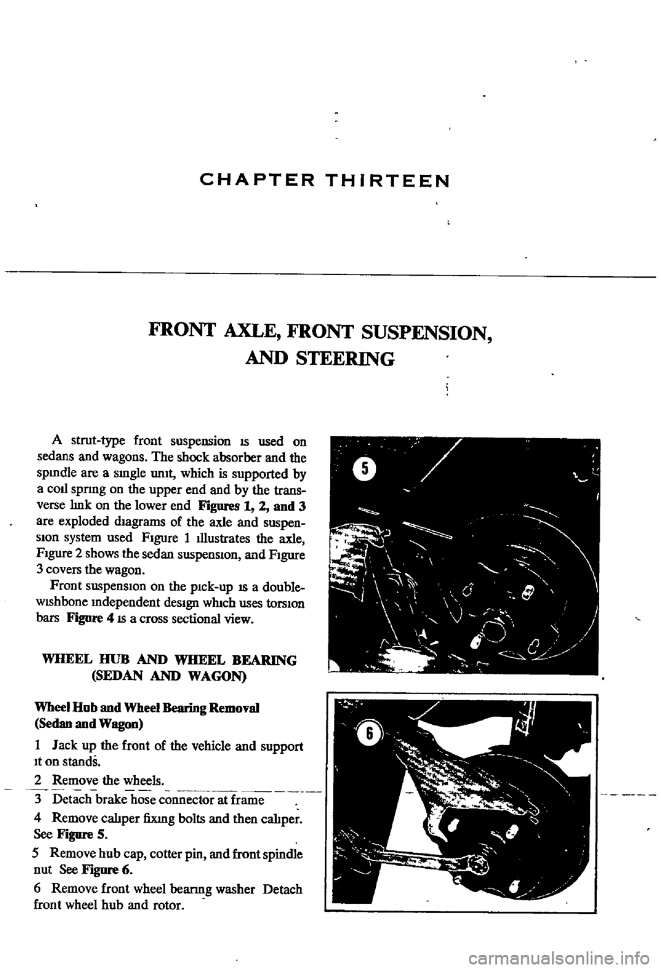
Remove
calIper
fiXlng
bolts
and
then
cahper
See
Figure
5
5
Remove
hub
cap
cotter
pin
and
front
spindle
nut
See
Figure
6
6
Remove
front
wheel
bearmg
washer
Detach
front
wheel
hub
and
rotor
ft
V
0
y
F
I
I
J
j
0
l
l
4
f
Page 245 of 252

l
INDEX
239
Rear
suspensIOn
wagon
Removal
40
92
Servlcmg
161
Termmals
94
Tightening
torques
162
Test
diagnosIs
97
Testmg
96
Troubleshootmg
10
5
Steenng
also
see
Suspension
front
I
Exploded
views
182
185
L
Seats
SpecIfications
186
DescnptIon
228
Troubleshooting
16
Exploded
View
front
4
door
sedan
232
SuspensIOn
front
pick
up
Exploded
VIew
front
pick
up
228
Axle
removal
175
Service
hmts
4
Inspection
and
repair
179
Shock
absorbers
sedan
154
Installation
179
Shock
absorbers
wagon
162
Posture
adjustment
181
Spark
plugs
Removal
177
CondlllOn
chart
21
Wheel
abgnment
182
InspectIon
and
servlcmg
21
Wheel
bearmg
adjustment
177
Recommended
types
112
Suspension
front
sedan
and
wagon
SpecificatIOns
and
tables
Inspection
and
repair
176
Adjustment
and
wheel
alignment
175
InstallatIOn
177
Brake
service
data
203
204
Lower
ball
Jomt
174
Brakes
203
204
Spnng
and
strut
assembly
173
Camshaft
beanngs
48
Stabilizer
173
Caster
and
camber
sedan
and
wagon
175
TenSIOn
rod
173
Clutch
134
Transverse
bnk
174
Clutch
service
data
134
Wheel
beanngs
177
Connectmg
rod
beanng
underslzes
52
Wheel
hubs
and
bearmgs
168
173
Dlstnbutor
112
SWItches
Dnveshaft
147
DescnptIon
205
Dnveshaft
service
dala
147
Exploded
View
through
1969
208
Engme
60
61
Exploded
view
1970
1972
207
Engme
service
data
60
61
General
4
Mam
bearmg
underslzes
52
T
Piston
rmg
gap
50
Rear
suspenSIOn
pick
up
167
Tail
gate
228
233
Rear
suspensIOn
torques
wagon
162
TenSIOn
rod
sedan
and
wagon
173
Steermg
186
Thermostat
TransmiSSion
manual
144
DescnptIon
89
TransmiSSion
service
data
manual
144
Inspection
and
replacement
89
Valve
spnng
47
Removal
89
Sprmg
and
strut
assembly
sedan
and
wagon
173
Tires
Spnngs
sedan
154
Wear
analYSIS
17
Stabilizer
sedan
and
wagon
173
TransmiSSion
automatic
Starter
Downshift
solenOid
147
Armature
95
Inhlbllor
SWItch
148
Beanngs
96
Kick
down
SWitch
147
Brush
holder
96
Lmkage
mspectIon
and
adjustment
148
Brushes
and
lead
WIre
95
011
checks
147
Cleaning
mspectIon
and
repair
94
Oil
leakage
147
Construcllon
92
TransmiSSion
manual
Disassembly
92
DescnptIon
134
Exploded
View
93
Disassembly
138
Field
COIl
94
Exploded
view
138
Magnetic
SWItch
96
Gear
assembly
exploded
view
139
Magnetic
SWItch
assembly
test
97
Inspection
and
repair
141
Operation
91
Installation
143
Overrunnmg
clutch
96
Reassembly
and
adjustment
142
Reassembly
96
Removal
134