Page 137 of 252
132
CHAPTER
ELEVEN
CD
NAnCO
22
20
21
r
i
T
l
C
r
Jl
i
i
18
Clutch
operating
cylinder
19
Piston
cup
20
PIston
21
Dust
cover
22
Push
rod
23
Bleeder
screw
24
Bleeder
cap
22
I
should
be
8
150
m
207mm
for
the
sedan
and
wagon
Pedal
heIght
should
be
591
m
150mm
for
the
pick
up
3
Apply
multI
purpose
grease
to
all
PIvot
pOInts
4
Bleed
all
aIr
out
of
the
sy
tem
as
dIscussed
below
OPERATING
CYLINDER
Operating
CyHnder
Removal
1
Remove
retum
spring
2
Disconnect
clutch
line
from
operating
cyl
inder
18
Ii
TOKICO
21
I
LL
18
23
24
I
I
3
Disconnect
pushrod
from
wIthdrawal
lever
4
Release
two
bolts
holdmg
operating
cylInder
to
clutch
hOUSIng
5
Remove
operating
cymder
from
clutch
hous
mg
Operating
CyHnder
Disassembly
1
Remove
dust
cover
2
Remove
snap
ring
All
other
parts
can
now
be
removed
See
Figure
10
Operating
CyHnder
Inspection
Check
all
parts
especIally
the
pIston
cup
for
wear
and
damage
Replace
if
defects
are
found
Page 202 of 252

BRAKES
IV
197
I
Ensure
that
the
brake
flUid
reservOir
at
the
master
cylmder
IS
full
and
that
the
vent
m
the
cap
is
open
2
Connect
a
plastIc
or
rubber
tube
to
the
bleeder
valve
on
the
nght
rear
wheel
Suspend
the
other
end
of
the
tube
m
a
Jar
or
bottle
filled
With
a
few
Inches
of
clean
brake
flwd
During
the
remaInIng
steps
keep
thiS
end
submerged
at
all
times
and
never
let
the
level
in
the
brake
flUid
reservoir
drop
below
full
3
Open
the
bleeder
valve
on
the
nght
rear
wheel
about
one
turn
Have
an
asSistant
depress
the
brake
pedal
slowly
As
soon
as
the
pedal
is
all
the
way
down
close
the
bleeder
valve
and
let
the
pedal
up
Repeat
thiS
step
as
many
tImes
as
necessary
until
pure
flUid
WithOUt
au
bubbles
comes
from
the
tube
4
Bleed
the
remammg
wheels
m
the
followmg
order
left
rear
nght
front
and
left
front
Keep
checkmg
the
brake
flUid
reservoir
to
make
cer
tam
It
doesn
t
TWl
out
of
flUId
5
When
all
wheels
are
bled
fill
the
reservOIr
to
the
full
level
Never
reuse
the
brake
flwd
bled
from
the
system
or
any
that
has
been
lymg
around
Start
With
a
fresh
contaIner
HANDBRAKE
Figures
19
next
page
and
20
page
199
are
exploded
views
of
the
handbrake
system
used
on
the
sedan
and
statIon
wagon
respectively
F1gDre
21
page
200
shows
the
pick
up
handbrake
system
Front
Cable
Removal
Sedan
and
Wagon
I
Release
handbrake
completely
Disconnect
the
front
cable
by
removmg
the
cleVIS
pm
that
connects
to
the
handbrake
control
stem
2
Screw
out
the
adJusting
nut
from
the
rear
end
of
the
front
cable
Disconnect
the
cable
from
the
center
lever
4
Remove
the
hand
brake
cable
clamp
from
under
the
verucle
Pull
out
the
lock
plate
fixmg
the
front
cable
to
the
front
cable
retamer
Ex
tract
the
front
cable
5
Unfasten
the
front
cable
outer
casing
from
the
bracket
Remove
the
cable
Front
Cable
Removal
Pick
up
I
Loosen
handbrake
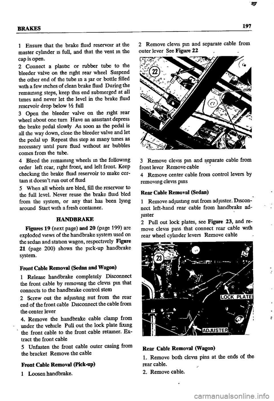
2
Remove
cleVIS
pm
and
separate
cable
from
outer
lever
See
Figure
22
p
3
Remove
cleVIS
pm
and
eparate
cable
from
front
lever
Removecable
4
Remove
center
cable
from
control
levers
by
removmg
cleViS
pms
Rear
Cable
Removal
Sedan
I
Remove
adJusting
nut
from
adJuster
DIScon
nect
left
hand
rear
cable
from
handbrake
ad
Juster
2
Pull
out
lock
plates
see
Figure
23
and
re
move
cleVIS
pms
that
connect
rear
cable
With
rear
wheel
cylJnder
levers
Remove
cable
Rear
Cable
Removal
Wagon
1
Remove
both
cleVIS
pins
at
the
ends
of
the
rear
cable
2
Remove
cable
Page 210 of 252
CHAPTER
FIFTEEN
BODY
ELECTRICAL
SYSTEM
Exploded
diagrams
of
the
various
systems
are
given
below
Inspection
of
the
constructIon
de
tails
as
given
m
the
exploded
diagrams
should
enable
the
mechanic
to
Identify
remove
repauj
replace
and
mstall
defectIve
parts
General
pro
cedures
are
given
at
the
end
of
the
chapter
WIRING
FJgUres
1
and
2
illustrate
the
winng
and
har
nesses
for
the
sedan
and
statIon
wagon
respect
2
VOLTAGE
REGULATOR
JOE
MARKER
l
AMJ
STARTER
MOTOR
IGHITION
COIL
t
ively
Figures
3
and
4
show
pick
up
winng
SWITCHES
FUSES
Figure
5
page
208
prOVides
details
of
switches
used
through
1969
Figure
6
page
207
covers
SWitches
used
smce
1970
FIgDI
eS
7
page
209
and
8
page
210
provide
further
SWitch
locatlon
and
fnnctIon
informatIon
Fuse
blocks
are
located
on
the
firewall
within
the
engine
compartment
ROOM
LAMP
COMBINATION
lAMP
LICENCE
lAMP
1
Engme
room
harness
2
Instrument
harness
3
Body
harness