1967 CHEVROLET CAMARO air filter
[x] Cancel search: air filterPage 619 of 659

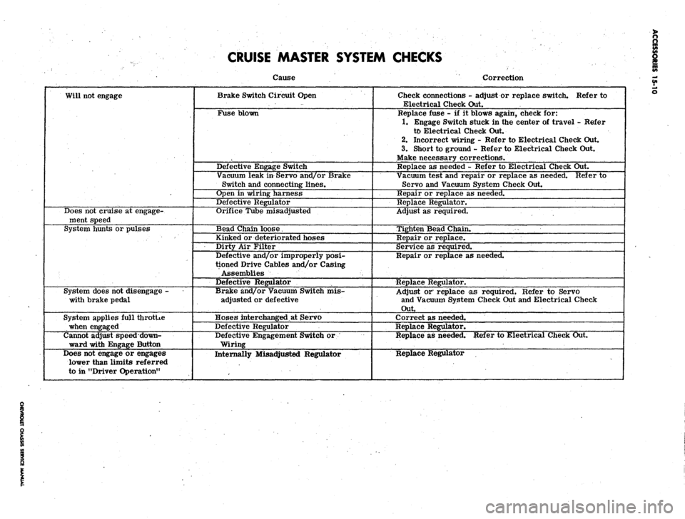
CRUISE MASTER SYSTEM CHECKS
Will not engage
Does not cruise at engage-
ment speed
System hunts or pulses
System does not disengage -
with brake pedal
System applies full throtUe
when engaged
Cannot adjust speed down-
ward with Engage Button
Does not engage or engages
lower than limits referred
to in "Driver Operation"
Cause
Brake Switch Circuit Open
Fuse blown
Defective Engage Switch
Vacuum leak in Servo and/or Brake
Switch and connecting lines.
Open in wiring harness
Defective Regulator
Orifice Tube misadjusted
Bead Chain loose.
Kinked or deteriorated hoses
Dirty Air Filter
Defective and/or improperly posi-
tioned Drive Cables and/or Casing
Assemblies
Defective Regulator
Brake and/or Vacuum Switch mis-
adjusted or defective
Hoses interchanged at Servo
Defective Regulator
Defective Engagement Switch or
Wiring
Internally Misadjusted Regulator
Correction
Check connections - adjust or replace switch. Refer to
Electrical Check Out.
Replace fuse - if it blows again, check for:
1.
Engage Switch stuck in the center of travel - Refer
to Electrical Check Out.
2.
Incorrect wiring - Refer to Electrical Check Out.
3.
Short to ground - Refer to Electrical Check Out.
Make necessary corrections.
Replace as needed - Refer to Electrical Check Out.
Vacuum test and repair or replace as needed. Refer to
Servo and Vacuum System Check Out.
Repair or replace as needed.
Replace Regulator.
Adjust as required.
Tighten Bead Chain.
Repair or replace.
Service as required.
Repair or replace as needed.
Replace Regulator.
Adjust or replace as required. Refer to Servo
and Vacuum System Check Out and Electrical Check
Out.
Correct as needed.
Replace Regulator.
Replace as needed. Refer to Electrical Check Out.
Replace Regulator
Page 620 of 659

ACCESSORIES 15-11
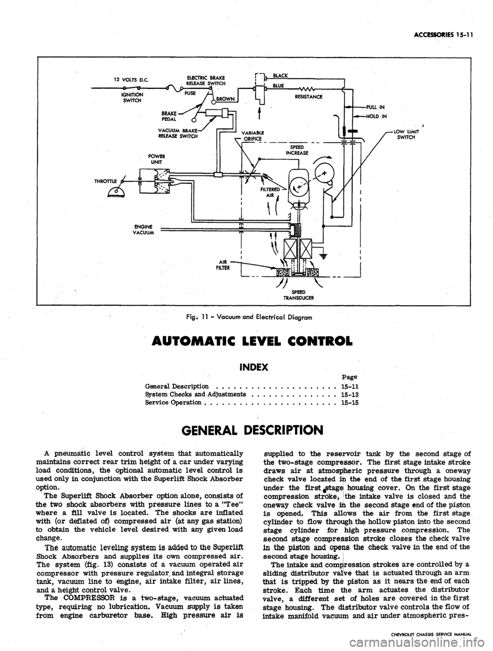
12 VOLTS D.C.
ELECTRIC BRAKE
RELEASE
IGNITION
SWITCH
ENGINE
VACUUM
TRANSDUCER
Fig.
11 - Vacuum and Electrical Diagram
AUTOMATIC LEVEL CONTROL
INDEX
Page
General Description . . 15-11
System Checks and Adjustments 15-13
Service Operation . 15-15
GENERAL DESCRIPTION
A pneumatic level control system that automatically
maintains correct rear trim height of a car under varying
load conditions, the optional automatic level control is
used only in conjunction with the Superlift Shock Absorber
option.
The Superlift Shock Absorber option alone, consists of
the two shock absorbers with pressure lines to a "Tee"
where a ill valve is located, the shocks are inflated
with (or deflated of) compressed air (at any gas station)
to obtain the vehicle level desired with any given load
change.
The automatic leveling system is added to the Superlift
Shock Absorbers and supplies its own compressed air.
The system (fig. 13) consists of a vacuum operated air
compressor with pressure regulator,
and
integral storage
tank, vacuum line to engine, air intake filter, air lines,
and a height control valve.
The COMPRESSOR is a two-stage, vacuum actuated
type, requiring no lubrication. Vacuum supply is taken
from engine carburetor base. High pressure air is
supplied to the reservoir tank by the second stage of
the two-stage compressor. The first stage intake stroke
draws air at atmospheric pressure through a oneway
check valve located in the end of the first stage housing
under the first ^tagei housing cover. On the first stage
compression stroke, the intake valve is closed and the
oneway check valve in the second stage end of the piston
is opened. This allows the air from the first stage
cylinder to flow through the hollow piston into the second
stage cylinder for jhigh pressure compression. The
second stage compression stroke closes the check valve
in the piston and opeijis the check valve in the end of the
second stage housing.
The intake and compression strokes are controlled by a
sliding distributor valive that is actuated through an arm
that is tripped by the piston as it nears the end of each
stroke. Each time the arm actuates the distributor
valve, a different set of holes are covered in the first
stage housing. The distributor valve controls the flow of
intake manifold vacuum and air under atmospheric pres-
CHEVROLET CHASSIS SERVICE MANUAL
Page 623 of 659

ACCESSORIES 15-14
Deflate system through service valve and disconnect
line at pressure regulator valve. Install test gauge on
regulator valve high pressure fitting.
Inflate system through service valve to maximum
available pressure.
NOTE: If available pressure is less than 140
psi,
start engine to build-up reservoir to this
pressure.
Regulated pressure should build-up to and hold
steady at 100-130 psi on test gauge.
Check regulated pressure by momentarily (not more
than one second) depressing valve core on test gauge
arid observe gauge reading.
If regulated pressure now reads less than 100 psi,
replace regulator assembly.
If regulated pressure exceeds 130 psi, replace regu-
lator assembly.
Control Valve Test
Exhaust (Superlifts Inflated)
1.
Disconnect control valve lever from link.
2.
Hold lever down in exhaust position until Superlifts
deflate or for a minimum of 18 seconds.
3.
If Superlifts deflate, perform Intake Check.
4.
If Superlifts do not deflate, remove exhaust adapter
from control valve and hold lever down as in Step 2.
Replace adapter, O-ring and filter if this deflates
Superlifts.
5.
Replace control valve if none of the above steps solve
problem.
Intake (Reservoir Pressure 125 psi Minimum)
1.
Disconnect overtravel lever from link.
2.
Hold lever up in intake position until Superlifts in-
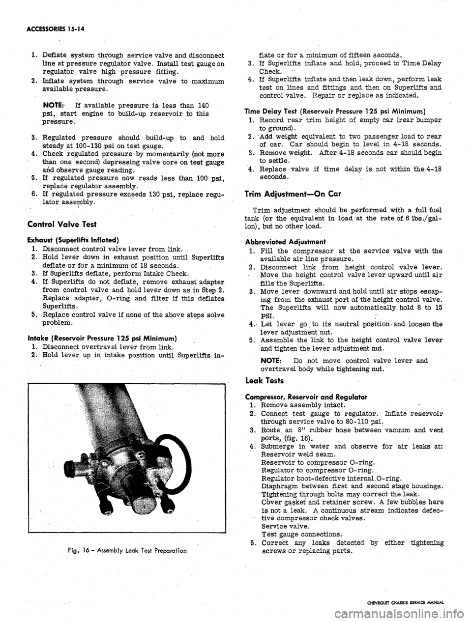
Fig.
16 - Assembly Leak Test Preparation
flate or for a minimum of fifteen seconds.
3.
If Superlifts inflate and hold, proceed to Time Delay
Check. '•
4.
If Superlifts inflate and then leak down, perform leak
test on lines and fittings and then on Superlifts and
control valve. Repair or replace as indicated.
Time Delay Test (Reservoir Pressure 125 psi Minimum)
1.
Record rear trim height of empty car (rear bumper
to ground).
2.
Add weight equivalent to two passenger load to rear
of car. Car should begin to level in 4-18 seconds.
3.
Remove weight. After 4-18 seconds car should begin
to settle.
4.
Replace valve if time delay is not within the 4-18
seconds.
Trim Adjustment—On Car
Trim adjustment should be performed with a full fuel
tank (or the equivalent in load at the rate of 6 lbs
./gal-
lon)
,
but no other load.
Abbreviated Adjustment
1.
Fill the compressor at the service valve with the
available air line pressure.
2.
Disconnect link from height control valve lever.
Move the height control valve lever upward until air
fills the Superlifts.
3.
Move lever downward and hold until air stops escap-
ing from the exhaust port of the height control valve.
The Superlifts will now automatically hold 8 to 15
PSI.
;
4.
Let lever go to its neutral position> and loosen the
lever adjustment nut.
5.
Assemble the link to the height control valve lever
and tighten the lever adjustment nut.
NOTE: Do not move control valve lever and
overtravel body while tightening nut.
Leak Tests
Compressor, Reservoir and Regulator
1.
Remove assembly intact.
2.
Connect test gauge to regulator. Inflate reservoir
through service valve to 80-110 psi.
3.
Route an 8" rubber hose between vacuum and vent
ports,
(fig. 16).
4.
Submerge in water and observe for air leaks at:
Reservoir weld seam.
Reservoir to compressor O-ring.
Regulator to compressor O-ring.
Regulator boot-defective internal.O-rihg.
Diaphragm between first and second stage housings.
' Tightening through bolts may correct the leak.
Cover gasket and retainer screw. A few bubbles here
is not a leak. A continuous stream indicates defec-
tive compressor check valves.
Service valve.
Test gauge connections.
5.
Correct any leaks detected by either tightening
screws or replacing parts.
CHEVROLET CHASSIS SERVICE MANUAL
Page 625 of 659

ACCESSORIES 15-16
Fig.
17 - Compressor, Regulator and Reservoir - Exploded View
1.
Regulator Assembly
2.
Adapter Assembly
3. Boot
4.
Sleeve
5. Piston
6. Spring
7. Retainer
8. "O" Ring
9. Valve Core
10..
Retainer, Screen
11.
Screen, Filter
12.
Adapter Assembly
13.
Adapter
14.
Valve Core
15.
"O" Ring
16..
Cap
17.
Screw, Regulator Retaining
18.
"O" Ring, Regulator to
Compressor
19.
Reservoir
20.
"O" Ring, Reservoir to
Compressor
21.
Thru Bolt, Reservoir
Retaining
22.,
Nut, Thru .Bolt Reservoir
23.
Thru Bolt, Compressor
Retaining
24.
Nut, Thru Bolt Compressor
25.
Compressor Assembly
26.
Housing, 2nd Stage
27.
Check Valve
28.
Spring
29.
Expansion Plug Retainer
30.
Housing 1st Stage
31.
Arm, Swivel
32.
Bushing
33.
Arm, Rocker .
34.
Pin, Rocker Arm Retaining
35.
Intake Valve
36,
Washer
37.
Spring, Intake Valve
Retaining
38.
Pin, Bushing
Retaining
39.
Piston Assembly
40.
Plate, Diaphragm
41.
Diaphragm
42.
Washer (.760-.765 I.D.)
43.
Retainer, Diaphragm
44.
Check Valve
45.
Spring
46.
Expansion Plug Retainer
47.
"O" Ring (.357-.367 I.D.)
48.
Seal (.569-.571)
49.
"O" Ring (.732-.742 I.D.)
50.
Seal (.943-.945)
51.
Piston
52.
Distributor Valve
53.
Bushing, Distributor Valve
54.
Washer (.160-. 163 I.D.)
55. Arm Assembly, Distributor
56. Screw
57. Spring, Valve Tension
58.
Bushing, Distributor Valve
Stop
59. Bussing, Arm Assembly
Stop
60.
Arm Actuating
61.
Spring, Arm Tension
62.
Screw, Arm Pivot
63.
Cover
64.
Gasket
65. Screw, Cover Retaining
66. Gasket, Cover
67. Mount, Flexible
68.
Adapter
NOTE: Position diaphragm retainer securely
to effect air tight seal against corprene washer.
Seals
1.
Inspect seals for evidence of excessive wear or
coring. If necessary replace seals and O-rings.
2.
Remove seals and O-rings from piston.
3.
Install new O-rings by rolling into groove. Relieve
any resulting twist.
4.
Install new seals using a piece of .020" shim stock,
(fig. 19). Make sure shim stock has no sharp edges
that may cut seal. Do not stretch seal more than
necessary to install. Seals should be installed so
they are not twisted.
Distributor Valve Mechanism and
Intake Valve (First Stage Housing)
NOTE: Actuate distributor valve with finger.
' Valve tension spring should press against dis-
tributor valve, holding it against either stop. If
valve action is not free and positive, it will be
necessary to rebuild using new parts in Distrib-
utor Valve and Arm Package. If action is free
CHEVROLET CHASSIS SERVICE MANUAL