1900 MITSUBISHI DIAMANTE clock
[x] Cancel search: clockPage 222 of 408
CHASSIS ELECTRICAL 6-19
1. Disconnect the negative battery cable.
are all built into 1 multi-function combination
2. Remove the instrument cluster, as outlined 1. Disconnect the negative battery cable.
earlier in this section. switch that is mounted on the steering col-
2. Using a small screwdriver or other suitable
umn. Refer to Section 8 for procedures re-
3. Remove the retaining screws for the instrument tool, carefully pry the retaining clips from either side
garding the combination switch.
cluster lens and cover assembly. Remove the cover of the switch trim plate.
3.
and lens. Carefully pull the switch and trim plate out of
,
4. Remove the retaining screws for the gauge or the instrument panel.
4. Detach the electrical connectors and remove
warning lamp to be replaced, then remove the gauge
the switch.
or warning lamp.
REMOVAL&INSTALLATION : 5. The installation is the reverse of removal.
To install:
5. Place the gauge or warning lamp into place
and tighten the retaining screws. 1. Disconnect the negative battery cable.
6. Install the instrument cluster lens and cover 2. Using a suitable prytool, disengage the switch
assembly. retaining tabs.
REMOVAL &INSTALLATION 7. Install the instrument cluster. 3. Gently pull the switch from the instrument
8. Connect the negative battery cable. panel.
4. Detach the electrical connector and remove the *On all models the headlights, turn signals,
switch. and on some models, the cruise control func-
5. The installation is the reverse of removal. tion are all built into 1 multi-function combi-
nation switch that is mounted on the steerinq
REMOVAL &INSTALLATION column. Refer to Section 8 for procedures 6
garding the combination switch.
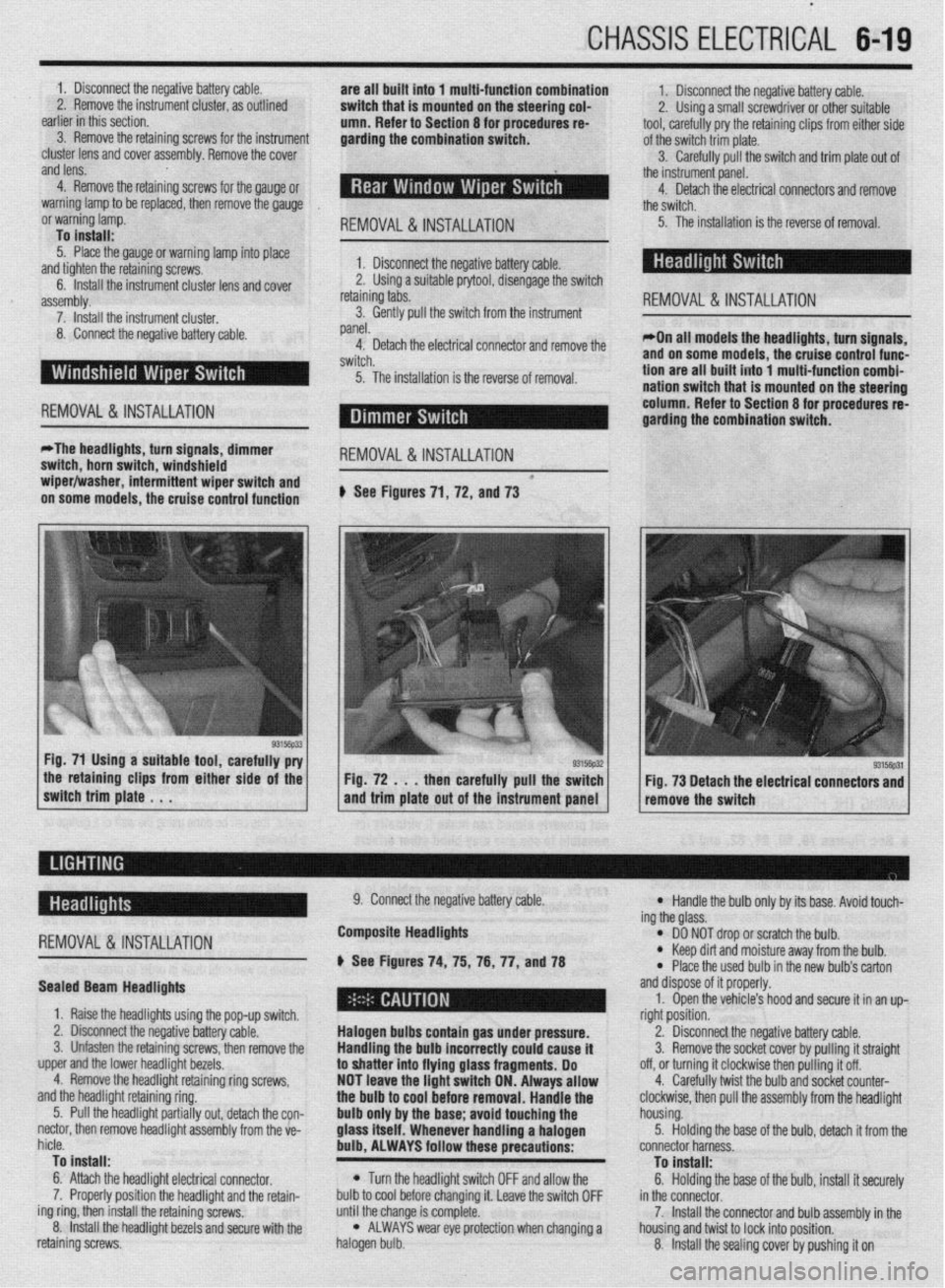
*The headlights, turn signals, dimmer
switch, horn switch, windshield
REMOVAL &INSTALLATION
wiper/washer, intermittent wiper switch and *
on some models, the cruise control function # See Figures 71, 72, and 73
the retaining clips from either side of the
switch trim plate . . . Fig. 72 . . . then carefully pull the switch
and trim plate out of the instrument panel Fig. 73 Detach the electrical connectors and
remove the switch
-
REMOVAL &INSTALLATION
Sealed Beam Headlights
1. Raise the headlights using the pop-up switch.
2. Disconnect the negative battery cable.
3. Unfasten the retaining screws, then remove the
upper and the lower headlight bezels.
4. Remove the headlight retaining ring screws,
and the headlight retaining ring.
5. Pull the headlight partially out, detach the con-
nectar, then remove headlight assembly from the ve-
hicle.
To install:
6. Attach the headlight electrical connector.
7. Properly position the headlight and the retain-
ing ring, then install the retaining screws.
8. Install the headlight bezels and secure with the
retaining screws. 9. Connect the negative battery cable.
Composite Headlights
6 See Figures 74, 75, 76, 77, anU78
Halogen bulbs contain gas under pressure.
Handling the
bulb incorrectly could cause it
to shatter into flying glass fragments. Do
NOT leave the light switch ON. Always allow
the bulb to cool before removal. Handle the
bulb only by the base; avoid touching the
glass itself. Whenever handling a halogen
bulb, ALWAYS follow these precautions:
l Turn the headlight switch OFF and allow the
bulb to cool before changing it. Leave the switch OFF
until the change is complete.
l ALWAYS wear eye protection when changing a
halogen bulb.
l Handle the bulb only by its base. Avoid touch-
ing the glass.
l DO NOT drop or scratch the bulb. l Keep dirt and moisture away from the bulb.
* Place the used bulb in the new bulb’s carton
and dispose of it properly.
1. Open the vehicle’s hood and secure it in an up-
right position.
2. Disconnect the negative battery cable.
3. Remove the socket cover by pulling it straight
off, or turning it clockwise then pulling it off.
4. Carefully twist the bulb and socket counter-
clockwise, then pull the assembly from the headlight
housing.
5. Holding the base of the bulb, detach it from the
connector harness.
To install:
6. Holding the base of the bulb, install it securely
in the connector.
7. Install the connector and bulb assembly in the
housing and twist to lock into position.
8. Install the sealing cover by pushing it on
Page 223 of 408
.
6-20 CHASSIS ELECTRICAL
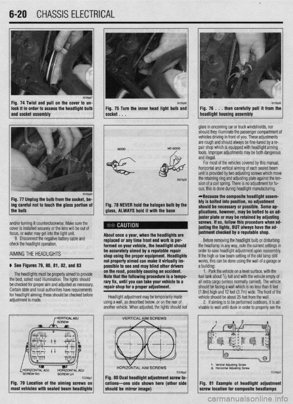
Fig. 74 Twist and pull on the cover to un-
lock it in order to access the headlight bulb
and socket assembly 93Mm Fig, 75 Turn the inner head light bulb and then carefully pull’ it from the
NO 0000 . glare in oncoming car or truck windshields, nor
should they illuminate the passenger compartment of
vehicles driving in front of you. These adjustments
are rough and should always be fine-tuned by a re-
pair shop which is equipped with headlight aiming
tools. Improper adjustments may be both dangerous
and illegal.
Fig. 77 Unplug the bulb from the socket, be-
L
ing careful not to touch the glass portion of
the bulb
I
6957Q39
Fig. 78 NEVER hold the halogen bulb by the
glass, ALWAYS hold it with the base
,
About once a year, when the headllgftts are
replaced or any time front end work is per-
formed on your vehicle, the headlight should
be accurately aimed by a reputable repair
shop uslng the proper equipment. Headlights
not properly aimed can make it virtually im-
possible to see ar Id may blind other drivers
ibly causing an accident.
Note that the’following procedure is a tempo-
rary fix, until you can take your vehicle to a
repair shop for a proper adjustment.
Headlight adjustment may be temporarily made
using a wall, as described below, or on the rear of
another vehicle. When adjusted, the lights should not For most of the vehicles covered by this manual,
horizontal and vertical aiming of eachsealed beam
unit is provided by two adjusting screws which move
the retaining ring and adjusting plate against the ten-
sion of a coil spring. There is no adjustment for fo-
cus; this is done during headlight manufacturing.
*Because the composite headlight assem-
bly is bolted into position, no adjustment
should be necessary or possible. Some ap-
plications, however, may be bolted to an ad-
juster plate or may be retained by adjusting
screws. If so, follow this procedure when ad-
@sting the lights, BUT always have the ad-
justment checked by a reputable shop.
Before removing the headlight bulb or disturbing
the headlamp in any way, note the current settings in
order to ease headlight adjustment upon reassembly.
If the high or low beam setting of the old lamp still
works, this can be done using the wall of a garage or
a building:
1. Park the vehicle on a level surface, with the
fuel tank about r/a full and with the vehicle empty of
all extra cargo (unless normally carried). The vehicle
should be facing a wall which is no less than 6 feet
(1.8m) high and 12 feet (3.7m) wide. The front of the
vehicle should be about 25 feet from the wall.
2. If aiming is to be performed outdoors, it is ad-
visable to wait until dusk in order to properly see the
% and/or turning it counterclockwise. Make sure the
cover is installed securely or the lens will be out of
focus, or water may get into the light unit.
9. Disconnect the negative battery cable and
check the headlight operation.
AIMINGTHE HEADLIGHTS
$ See Figures 79, 88, 81, 82, and 83
The headlights must be proper’ ’ ’ ’
the best, safest road illumination. ’ ’
ly armea IO provrae
The lights should
:.__1__1 __ - -___-_-. on the road, POSSI
be checked for proper aim and adfusreu as IlweSYdly. Certain state and local authorities have requirements
for headlight aiming; these should be checked before
adjustment is made.
SCFEWRH
ScFlEwLn
TCcAssa
Fig. 79 Location of the aiming screws on
most vehicles with sealed beam headlights
TCCAE@ Fig. 88 Dual headlight adjustment screw lo-
cations--one side shown here (other side
should be mirror image)
2.
TCC&z3
Fig. 81 Example of headlight adjustment
screw location for composite headlamps
Page 224 of 408
CHASSIS ELECTRICAL 6-21
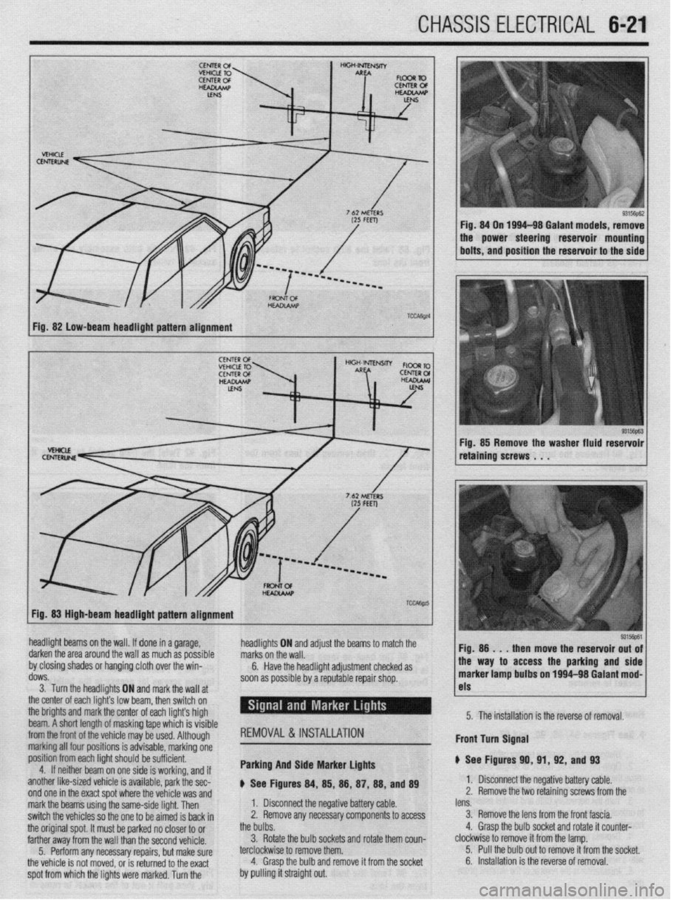
Fig. 82 low-beam headlight pattern alignment
93156pE.3 Fig. 85 Remove the washer fluid reservoir
retaining screws . . .
Fig. 83 High-beam headlight pattern alignment
headlight beams on the wall. If done in a garage,
darken the area around the wall as much as possible
by closing shades or hanging cloth over the win-
dows.
3. Turn the headlights ON and markthe wall at
the center of each light’s low br ram, then switch on
the brights and mark the center of each lights high
beam. A short length of maskin g tape which is visible
from the front of the
whir+ ma . ._..._._ . .._ y be used. Although
marking all four po:
sitions is advisable, marking one
position from each
light should be sufficient.
4. If neithar he; ~. __
Irn on one side is working, and if
another like-sized vehicle is available, park the sec-
nnri nm in the wart cnnt whrw the whirlo um md
headli! jhts ON and adjust the beams to marcn me
I. Disconnect the negative battery cable. marks on the wall.
2. Remove any necessary components to access 6.
the bulbs. Have the headlight adjustment checked as
soon as possible by a reputable repair shop.
3. Rotate the bulb sockets and rotate them coun-
terclockwise to remove them.
4. Grasp the bulb and remove it from the socket REMOVAL&INSTALLATION
Parking And Side Marker Lights
p See Figures 84, 85, 88, 87, 88, and 89 !ss the parking and side
1~ nn loo4-98 Galant mod-
I
1 I-
5315@61
lens. 1 Fio. 8
then move the reservoir out of
3. Remove the lens from the front fascia.
4. Grasp the bulb socket and rotate it counter- marker lamp bult, _.. ._“~-
clockwise to remove it from the lamp.
5. Pull the bulb out to remove it from the socket. 5. The installation is the reverse of removal.
6. Installation is the reverse of removal. Front turn Signal
p See Figures 91
1. Disconnect tl
2. Remove the t 0, 91, 92, and 93
I(? n,-.nn+:.m b.Hnn, nnL.L
z Ill7yau”e “allcly ul”IC. 10 retainino screws from the
spot from which the lights were marked. Turn the . ..I_ WIIY I.8 %,I” V”UVL”fdYI T.II”IU Lll” “VlllUlY ,.UU U,,” mark the beams using the same-side light. Then
switch the vehicles so the one to be aimed is back in
the original spot. It must be parked no closer to or
farther away from the wall than the second vehicle.
5. Perform any necessary repairs, but make sure
the vehicle is not moved, or is returned to the exact
by pulling it straight out.
Page 225 of 408
6-22 CHASSIS ELECTRICAL
b
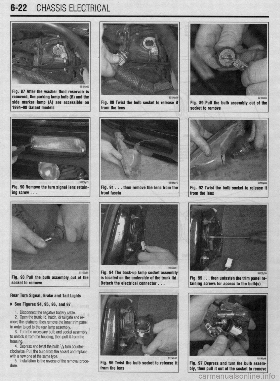
Fig. 87 After the washe: fluid reservoir
removed, the parking lamp bulb (B) and the
side marker lamp (A) are accessible on
Fig. 88 Twist the bulb socket to release it
1994-98 Galant models
from the lens Fig. 89 Pull the bulb assembly out of the
socket to remove
g3156p71 / Fig 90 Remove the turn signal lens retain-
ing’screw . . . . then remove the lens from the
Rear Turn Signal, Brake and Tail lights
p See Figures 94, 95, 96, and 97.
1. Disconnect the negative battery cable.
2, Open the trunk lid, hatch, or tailgate and re-
move the retainers, then remove the inner trim panel
in order to get to the rear lamp assembly.
3. Turn the necessary bulb and socket assembly
to unlock it from the housing, then pull it from the
housing.
4. Depress and twist the bulb l/a turn counter-
clockwise. Pull the bulb from the socket and replace
with a new one of the same type.
5. Installation is the reverse of the removal proce-
rl. ._^
UUIt?. Fig. 96 Twid
: the bulb socket to release it
from the lens
93156p69 Fig. 92 Twist the bulb socket to release it
from the lens
I
Fig. 94 The back-up lamp socket assembly
Pull the bulb assembly
out of the
located on the underside of the trunk lid.
. . . then unfasten the trim panel re-
Fig. 97 Depress and turn the bulb assem-
bly, then pull it out of the socket to remove
Page 226 of 408
![MITSUBISHI DIAMANTE 1900 Repair Manual CHASSIS ELECTRlCiL 6-23
93156P57 Fig. 98 The back-up lamp socket assembly Fig. 99 Twist the bulb socket to release the
is located on the underside of the trunk lid locking tabs from the lens *1W5y]](/manual-img/19/57096/w960_57096-225.png "MITSUBISHI DIAMANTE 1900 Repair Manual CHASSIS ELECTRlCiL 6-23
93156P57 Fig. 98 The back-up lamp socket assembly Fig. 99 Twist the bulb socket to release the
is located on the underside of the trunk lid locking tabs from the lens *1W5y]")
CHASSIS ELECTRlCiL 6-23
93156P57 Fig. 98 The back-up lamp socket assembly Fig. 99 Twist the bulb socket to release the
is located on the underside of the trunk lid locking tabs from the lens *1W5y] Fig 100 Pull the bulb assembly straight out
of the socket to remove it
Back-up light
u See Figures 98, 99, and 100
1 I Disconnect the negative battery cable.
2. Open the trunk lid.
3. If equipped, remove the trim on the underside
of the trunk lid.
4. Turn the socket counterclockwise ‘14 of a turn
to release it from the lens.
5. Pull the bulb out to remove it from the socket,
6. The installation is the reverse of removal.
7. Connect the negative battery cable.
8. Verify the operation of the lamp.
Side Marker light
# See Figures 101, lOi, 103, and 104 I. Remove the two retaining screws from the 2. Open the trunk lid and detach the electrical
lens. connector from the lamp assembly.
2. Remove the lens from the rear fascia. 3. Remove the retaining screw holding the lamp
’ 3. Grasp the bulb socket and rotate it counter- assembly.
clockwise to remove it from the lamp. 4. Lower the lamp assembly from the lamp lens.
4. Pull the bulb out to remove it from the’socket. 5. Rotate the bulb clockwise while pushing it
5. Installation is the reverse of removal. gently inward to remove it from the socket.
6. The installation is the reverse of removal. .
High-mount Brake light
199fH6 MIllAGE, 1990-93 GALANT, AND
799446 GALANT 7992-96 DlAMANTE
p See Figures 105, 106, 107, 108, and 109 1, Disconnect the negative battery cable.
2. On the Mirage and Galant, remove the square
1. Disconnect the negative battery cable.
*The lamp assembly is accessible from the
trunk underneath the package shelf. retainer clips or bolts from the high-mount brake
light cover and remove the cover.
3. On the Diamante, press gently inward on the
sides of the liaht cover and remove it from the lamp.
1 taining screw . ~ . 93156p73 1 Fig 101 Remove the side marker light re-
93156p75 1 / ;;x,;;:,sdhen puii the lens awaG;:: 1 1 fror;l the iens Fig 103 Twist the bulb socket to release it
Fig. 104 Pull the bulb assembly straight out
of the socket to remove Fig. 105 Detach the high-mount brake
light electrical connector Fig. 106 Remove the lamp retaining screws
. a *
Page 227 of 408
.
6-24 CHASSIS ELECTRICAL
Fig. 107
. . . then lower the lamp assembly
for access to the bulbs
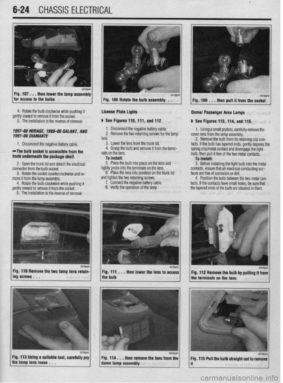
4. Rotate the bulb clockwise while pushing it
.,
gently inward to remove it from the socket.
5. The installation is the reverse of removal.
1997-00 MIRAGE, 1994-00 GALANT, AND
f 997-90 DIAMANTE
1. Disconnect the negative battery cable.
*The bulb socket is accessible from the
trunk underneath the package shelf.
2. Ooen the trunk lid
and detach the elwtrical connector from the bulb socket,
3. Rotate the socket counterclockwise and re-
move it from the lamp assembly.
4. Rotate the bulb clockwise while pushing
it gently inward to remove it from the socket. Fig. 108 Rotate the bulb assembly. . .
License Plate lights
p See Figures 110,111, and 112
1. Disconnect the negative battery cable.
2. Remove the two retaining screws for the lamp
lens.
3. Lower the lens from the trunk lid.
4. Grasp the bulb and remove it from the termi-
nals on the lens.
To install:
5. Place the bulb into place on the lens and
lightly press into the terminals on the lens.
6. Place the lens into position on the trunk lid
and tighten the two retaining screws.
7. Connect the negative battery cable.
8. Verify the operation of the lamp. Dome/ Passenger Area lamps
p See Figures 113, 114, and 115
1, Using a small prytool, carefully remove the
cover lens from the lamp assembly.
2. Remove the bulb from its retaining clip con-
tacts. If the bulb has tapered ends, gently depress the
spring clip/metal contact and disengage the light
bulb, then pull it free of the two metal contacts.
To install:
3. Before installing the light bulb into the metal
contacts, ensure that all electrical conducting sur-
faces are free of corrosion or dirt.
4. Position the bulb between the two metal con-
tacts. If the contacts have small holes, be sure that
the tapered ends of the bulb are situated in them.
5. The installation is the reverse of removal.
Fig. 110 Remove the two lamp lens retain-
ing screws . . . Fig. ill . . .
then lower the lens to access
the bulb Fig. 112 Remove the bulb by pulling it from
the terminals on the lens
Page 228 of 408
CHASSIS ELECTRICAL 6-25
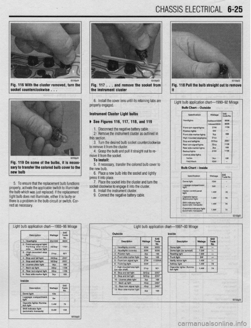
ove the socket from ig. 118 Pull the bulb straight out to remove
6. Install the cover lens until its retaining tabs are
properly engaged. ’
Light bulb application chart-1990-92 Mirage
Bulb Chart - Outaide
Instrument Cluster light bulbs
b See Figures 116,llf,ll8, and 119
1. Disconnect the negative battery cable.
2: Remove the instrument cluster as outlined in
this section.
3. Turn the desired bulb socket counterclockwise
to remove it from the cluster.
, 4. Grasp the bulb and pull it straight out to re-
move it from the socket.
I 1 Lmelatel~hls
Fig. 119 On some of the bulbs, it is neces-
1 ;;tbqrlrnsferthe colore ’ ’ ” . .’ ’
1 EL&
!a OUID cover IO me
Bulb Chart-In
*__. . __.
, , JvR,,Is~,,o~
press i+ in+n n,app
II llll” ~“UVV.
To install:
5. If necessary, transfer the colored bulb cover to
the new bulb.
6. Place a new bulb into the socket and lightly
Place the socket into the cluster and turn the
,“. II pithpr it ic faldtv nr 9. Connect the negative battery cable.
I
Outside Inside
Page 232 of 408
CHASSIS ELECTRlCiL 6-29
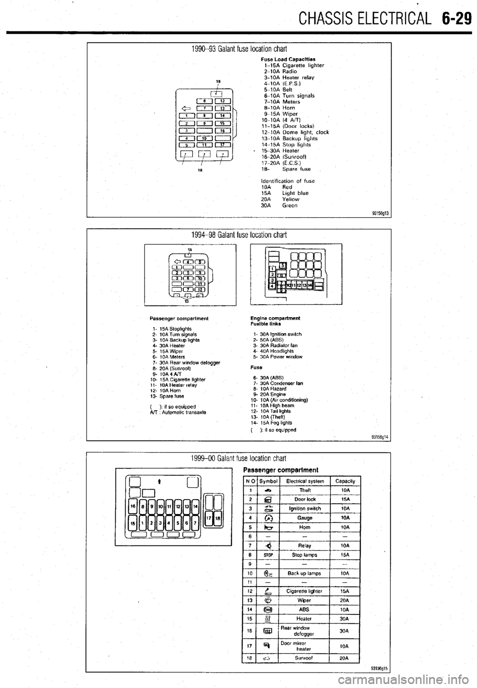
1990-93 Galant fuse location chart Fuse Load Capacities
l-15A Cigarette hghter
Z-10A Radm
3-10A Heater relay
4-10A (E P S.)
5-10A Belt
6-10A Turn signals
7-10A Meters
6-10A Horn
9-15A Wiper
lo-10A (4 A/T)
ll-15A (Door locks)
12-10A Dome hght, clock
13-10A Backup hghts
14-15A Stop hghts
15-30A Heater
16m20A (Sunroof)
17-20A (ECS)
1% spare fuse
ldentlfxation of fuse
10A Red
15A Light blue
20A Yellow
30A Green
93156g13
1994-98 Galant fuse location chart
Passenger compartment
1. 15A StoplIghts
2- 10A Turn signals
3- 1 OA Backup Itghts
4. 30A Heater
5. i5A Wiper
6- IOA Meters
7. 30A Rear wndow defogger
;: fo& fl$oof)
IO- 15A Cagaretle lighler
11. 10A Heater relay
12. IOA Horn
13. Spare fuse
( ): II so equipped
A!T Automallc transaxle Engine compartment
Fusible links
I- 30A Ignition swlch
2. 50A (ABS)
3. 30A Radiator fan
4. 40A Headkghts
5. 30A Power wndow
Fuse
6- 30A (ABS)
7. 30A Condenser fan
6. 10A Hazard
9. 20A Engine
10. 10A (Au conditioning)
11. 10AHigh beam
12. 10ATall lkghts
13. 10A (Theft)
14. i5A Fog lkghls
( ): If so equipped
93156g14
1999-00 Galant fuse location chart