1900 MITSUBISHI DIAMANTE ECO mode
[x] Cancel search: ECO modePage 205 of 408
6-2 CHASSIS ELECTRICAL
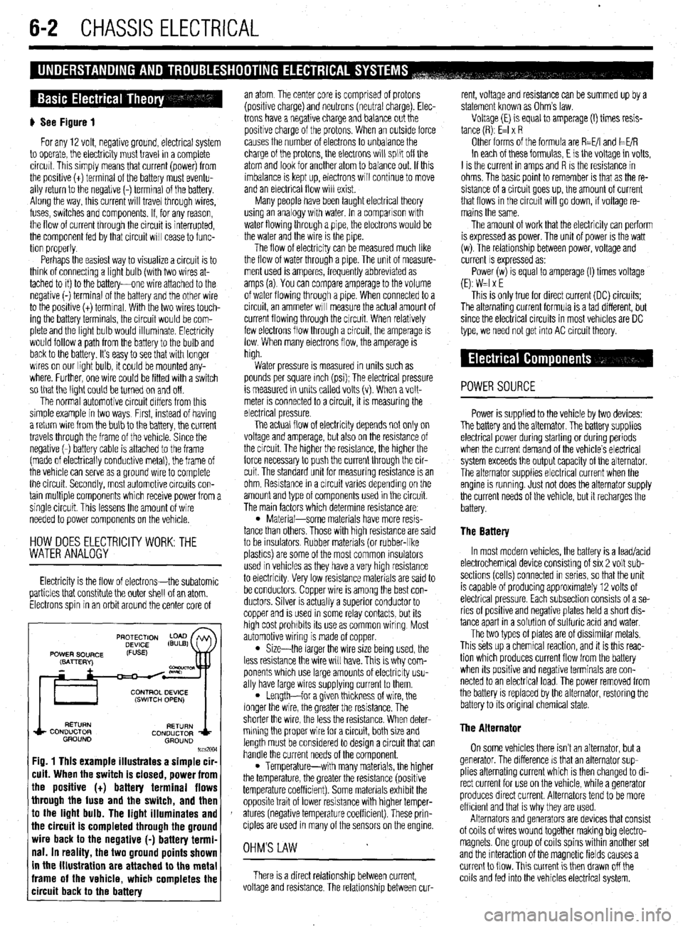
) See Figure 1
For any 12 volt, negative ground, electrical system
to operate, the electricity must travel in a complete
circurt. This simply means that current (power) from
the posibve (t) terminal of the battery must eventu-
ally return to the negative (-) terminal of the battery.
Along the way, this current will travel through wires,
fuses, switches and components. If, for any reason,
the flow of current through the circuit is interrupted,
the component fed by that circuit will cease to func-
tion properly.
Perhaps the easiest way to visualize a circuit is to
think of connecting a light bulb (with two wires at-
tached to it) to the battery-one wire attached to the
negative (-) terminal of the battery and the other wire
to the positive (t) terminal. With the two wires touch-
ing the battery terminals, the circuit would be com-
plete and the light bulb would illummate. Electricity
would follow a path from the battery to the bulb and
back to the battery. It’s easy to see that wrth longer
wires on our light bulb, it could be mounted any-
where. Further, one wire could be fitted with a switch
so that the light could be turned on and off.
The normal automotive circuit differs from this
simple example in two ways, Frrst, instead of having
a return wire from the bulb to the battery, the current
travels through the frame of the vehicle. Since the
negative (-) battery cable is attached to the frame
(made of electrically conductive metal), the frame of
the vehicle can serve as a ground wire to complete
the circuit. Secondly, most automotive circuits con-
tain multiple components which receive power from a
single circuit. This lessens the amount of wire
needed to power components on the vehicle.
HOW DOES ELECTRlClTYWORK:THE
WATER ANALOGY
Electricity is the flow of electrons-the subatomic
particles that constitute the outer shell of an atom.
Electrons spin in an orbit around the center core of
RETURN
RETURN
CONDUCTOR
CONDUCTOR
GROUND
GROUND
lccs2w
Fig. 1 This example illustrates a simple cir-
cuit. When the switch is closed, power from
the positive (t) battery terminal flows
through the fuse and the switch, and then
to the light bulb. The light illuminates and
the circuit is completed through the ground
wire back to the negative (-) battery termi-
nal. In reality, the two ground points shown
in the illustration are attached to the metal
frame of the vehicle, which completes the
circuit back to the battery
an atom The center core is comprised of protons
(positive charge) and neutrons (neutral charge). Elec-
trons have a negative charge and balance
out the
positive charge of the protons. When an outside force
causes the number of electrons to unbalance the
charge of the protons, the electrons will split off the
atom and look for another atom to balance out. If this
imbalance is kept up, electrons will continue to move
and an electrical flow will exist.
Many people have been taught electrical theory
using an analogy with water. In a comparison wrth
water flowing through a pipe, the electrons would be
the water and the wire is the pipe.
The flow of electricity can be measured much like
the flow of water through a pipe. The unit of measure-
ment used is amperes, frequently abbreviated as
amps (a). You can compare amperage to the volume
of water flowing through a pipe. When connected to a
circuit, an ammeter WIII measure the actual amount of
current flowing through the circuit. When relatively
few electrons flow through a circuit, the amperage is
low. When many electrons flow, the amperage is
high.
Water pressure is measured in units such as
pounds per square inch (psi); The electrical pressure
is measured in unrts called volts (v). When a volt-
meter is connected to a circuit, it is measuring the
electrical pressure.
The actual flow of electricity depends not only on
voltage and amperage, but also on the resistance of
the circuit The higher the resistance, the higher the
force necessary to push the current through the cir-
cuit. The standard unit for measuring resistance is an
ohm. Resistance in a crrcuit varies dependmg on the
amount and type of components used in the circuit.
The main factors which determine resistance are:
l Material-some materials have more resis-
tance than others Those with high resistance are said
to be insulators Rubber materials (or rubber-like
plashcs) are some of the most common insulators
used in vehicles as they have a very high resistance
to electricity Very low resistance materials are said to
be conductors. Copper wire is among the best con-
ductors. Silver is actually a superior conductor to
copper and is used in some relay contacts, but its
high cost prohibits its use as common wiring Most
automotive wiring is made of copper.
l Size-the larger the wire size being used, the
less resistance the wire will have. This IS why com-
ponents which use large amounts of electricity usu-
ally have large wires supplying current to them.
l Length-for a given thickness of wire, the
longer the wire, the greater the resistance. The
shorter the wire, the less the resistance. When deter-
mining the proper wire for a circuit, both size and
length must be considered to design a circuit that can
handle the current needs of the component.
l Temperature-with many materials, the higher
the temperature, the greater the resistance (positive
temperature coefficient). Some materials exhibit the
opposite trait of lower resistance with higher temper-
atures (negative temperature coefficient). These prin-
ciples are used in many of the sensors on the engine
OHM'S LAW
There is a direct relationship between current,
voltage and resistance. The relationship between cur- rent, voltage and resistance can be summed up by a
statement known as Ohm’s law.
Voltage (E) is equal to amperage (I) times resis-
tance (R): E=l x R
Other forms of the formula are R=E/I and I=E/R
In each of these formulas, E is the voltage in volts,
I is the current in amps and R IS the resistance in
ohms. The basic point to remember is that as the re-
sistance of a circuit goes up, the amount of current
that flows in the circuit will go down, if voltage re-
mains the same.
The amount of work that the electricity can perform
is expressed as power. The unit of power is the watt
(w). The relationship between power, voltage and
current
IS expressed as:
Power(w) is equal to amperage (I) times voltage
(E): W=l x E
This is only true for direct current (DC) circuits:
The alternating current formula is a tad different, but
since the electrical circuits in most vehicles are DC
type, we need not get into AC circuit theory.
POWERSOURCE
Power is supplied to the vehicle by two devices:
The battery and the alternator. The battery supplies
electrical power during starting or during periods
when the current demand of the vehicle’s electrical
system exceeds the output capacity of the alternator.
The alternator supplies electrical current when the
engine is running
Just not does the alternator supply
the current needs of the vehicle, but it recharges the
battery.
The Battery
In most modern vehicles, the battery is a lead/acid
electrochemical device consisting of six 2 volt sub-
sections (cells) connected in series, so that the unit
is capable of producing approximately 12 volts of
electrical pressure. Each subsection consists of a se-
ries of positive and negative plates held a short dis-
tance apart in a solutron of sulfuric acid and water.
The two types of plates are of dissimilar metals,
This sets up a chemrcal reaction, and it is this reac-
tion which produces current flow from the battery
when Its positive and negattve terminals are con-
nected to an electrical load. The power removed from
the battery is replaced by the alternator, restoring the
battery to its original chemical state.
The Alternator
On some vehicles there isn’t an alternator, but a
generator. The difference IS that an alternator sup-
plies alternating current which is then changed to di-
rect current for
use on the vehicle, while a generator
produces direct current. Alternators tend to be more
efficient and that is why they are used.
Alternators and generators are devices that consist
of coils of wires wound together making big electro-
magnets. One group of coils spins within another set
and the interaction of the magnetic fields causes a
current to flow. This current is then drawn off the
coils and fed into the vehicles electrical system.
Page 282 of 408
DRIVETRAIN 7-3
7. Remove the connection for the clutch release
38. Install the battery.
bolt to 54 ft. Ibs. (73 Nm). Install the front engine roll
cylinder and without disconnecting the hydraulic line,
39. If equipped with Active-ECS, connect the air
stopper through-bolt and hand-tighten. Once the full
and secure it aside.
compressor.
weight of the engine is on the mounts, tighten the
8. Disconnect the backup light switch harness
40. Make sure the vehicle is level when refilling
bolt to 42 ft. Ibs. (57 Nm).
and position aside.
the transaxle. Use Hypoid gear oil or equivalent, GL-
30.
Install the triangular stay bracket and tighten
9. Detach the starter electrical connections, if
4 or higher.
the mounting bolts to 65 ft. Ibs. (88 Nm).
necessary, remove the starter motor and position
41. Check the transaxle and transfer case for
31. Connect the clutch release cylinder.
aside.
proper operation. Make sure the reverse lights come
32. Install the halfshafts, using new circlips on
10. Remove the transaxle mount bracket.
on when in reverse.
the axle ends.
11. Remove the upper transaxle mounting bolts.
12.
Raise the vehicle and support safely on jack-
1!I94-Ol? MODELS
stands.
13. Remove the undercover and the front wheels. 1. Disconnect the negative battery cable and When histalling the axleshaft, keep the in-
14.
Remove the cotter pin and disconnect the tie wait at least 90 seconds before performing any work. board joint straight in relation to the axle, so
rod end from the steering knuckle. 2. Remove the air cleaner and intake hoses. not to damage the oil seal lip of the
15. Remove the self-locking nut from the half- 3. Drain the transaxle into a suitable waste con- transaxle, with the serrated part of the half-
ShaftS. tainer. shaft.
16.
Disconnect the lower arm ball joint from the 4. Remove the cotter pins and clips securing the
steering knuckle. select and shift cables and remove the cable ends 33. Connect the tie rod and ball joints to the steer-
17. Remove the halfshafts from the transaxle. from the transaxle. ing knuckle. Tighten the ball joint self-locking nuts to
18. On AWD models, disconnect the front ex- 5. If equipped with Active-ECS, disconnect the 48 ft. Ibs. (65 Nm). Tighten the tie rod end nut to 21 ft.
haust pipe. air compressor. Ibs. (28 Nm) and secure with a new cotter pin.
19.
On AWD ‘models, remove the transfer case by 6. Disconnect the backup light switch harness 34.
Connect the damper fork to the lower control
removing the attaching bolts, moving the transfer and position aside. arm and tighten the through-bolt to 65 ft. Ibs. (88 Nm).
case to the left and lowering the front side. Remove it 7. Disconnect the speedometer electrical con- 35.
Connect the stabilizer link to the damper fork,
from the rear driveshaft. Be careful of the oil seal. Do nectar, from the transaxle assembly. and tighten the self-locking nut to 29 ft. Ibs. (39 Nm).
not allow the driveshaft to hang; once the front is re- 8. Remove the starter motor and position aside. 36. Install the underpan.
moved from the transfer, tie it up. Cover the transfer 9. Using special tool M2203827 or equivalent, 37. Install wheels and lower vehicle.
case openings to keep out dirt. support the engine assembly. 38. Install the transaxle mount bracket to the
20.
Remove the cover from the transaxle bell- 10. Remove the rear roll stopper mounting transaxle, and tighten the mounting nuts to 32 ft. Ibs.
housing. bracket. (43 Nm).
21. On AWD models, remove the crossmember 11. Remove the transaxle mount bracket. 39. install the rear roll stopper mounting bracket.
and the triangular gusset. 12. Remove the upper transaxle mounting bolts. 40.
Remove the engine support. Tighten the
22. Remove the transaxle lower coupling bolt. It 13. Raise and safely support the vehicle. transaxle mount through-bolt to 51 ft. Ibs. (69 Nm)
is just above the halfshaft opening on FWD or trans- 14. Remove the front wheel assemblies. and tighten the front engine roll stopper through-bolt.
fer case opening on AWD. 15. Remove the right hand undercover. 41. Install the upper transaxle mounting bolts
23.
Support the weight of the engine from above 16. Remove the cotter pin and disconnect the tie and tighten to 35 ft. Ibs. (48 Nm).
(chain hoist). Support the transaxle using a transmis- rod end, from the steering knuckle. 42. Install the starter motor.
sion jack and remove the remaining lower mounting 17. Disconnect the stabilizer bar link, from the 43. Attach the backup light switch and the
bolts. damper fork. speedometer connector.
24. On turbocharged vehicle, be careful not to 18. Disconnect the damper fork, from the lateral 44.
Connect the select and shift cables and install
damage the lower radiator hose with the transaxle lower control arm. new cotter pins.
housing during removal. Wrap tape on both the lower 19. Disconnect the later lower arm, and the com- 45.
Install the air cleaner and the air intake hose.
hose and the transaxle housing to prevent damage. pression arm, lower ball joints, from the steering 46. Connect the negative battery cable.
Move the transaxle assembly to the right and care- knuckle. 47. Make sure the vehicle is level, and refill the
fully lower it from the vehicle. 20. Pry the halfshafts from the transaxle, and se- transaxle.
To install: cure aside. 48.
Check the transaxle for proper operation. Make
25.
Install the transaxle to the engine and install 21. Remove the connection for the clutch release sure the reverse lights come on when in reverse.
the mounting bolts, Tighten the bolts to 35 ft. Ibs. (48 cylinder and without disconnecting the hydraulic line,
Nm). Install the transaxle lower coupling bolt. secure aside.
26.
Install the underpan, crossmember and the 22. Remove the cover from the transaxle bell-
triangular gusset. housing.
27.
Install the transfer case on AWD models and 23. Remove the engine front roll stopper REMOVAL&INSTALLATION
connect the exhaust pipe. through-bolt.
28.
Install the halfshafts, using new circlips on 24. Remove the crossmember and the triangular ) See Figures 1 thru 13
the axle ends. Try to keep the inboard joint straight in right hand stay.
relation to the axle. Be careful not to damage the oil 25. Support the transaxle, using a transmission
seal lip of the transaxle with the serrated part of the jack, and remove the transaxle lower coupling bolt.
halfshaft.
29. Connect the tie rod and ball joint to the steer- *The coupling bolt threads from the englne
side, into the transaxle, and is located just
ing knuckle.
30. Install the transaxle mount bracket. above the halfshaft opening.
31. Install wheels and lower vehicle. Retorque 26. Slide the transaxle rearward and carefully
axle shaft nuts to 145-188 ft. Ibs. (200-260 Nm). lower it from the vehicle.
32. Install the starter motor. To install:
33. Connect the backup light switch and the 27. Install the transaxle to the engine. Install the
speedometer cable. mounting bolts and tighten to 35 ft. Ibs. (48 Nm). In-
34. Install the clutch release cylinder. stall the transaxle lower coupling bolt and tighten to
35.
Connect the select and shift cables and install 22-25 ft. Ibs. (30-34 Nm).
new cotter pins. 28. Install the cover to the transaxle bellhousing
36. Install the air intake hose. and tighten the mounting bolts to 7 ft. Ibs. (9 Nm).
37. Install the auto-cruise actuator and bracket. 29. Install the crossmember and tighten the front
mounting bolts to 65 ft. Ibs. (88 Nm) and the rear
Page 288 of 408
DRIVETRAIN 7-9
*When adjusting the clutch pedal height or
the clutch pedal clevis pin play, be careful
not to push the pushrod toward the master
cylinder.
d. Check that when the clutch pedal is de-
pressed all the way, the interlock switch switches
over from ON to OFF.
ADJUSTMENT
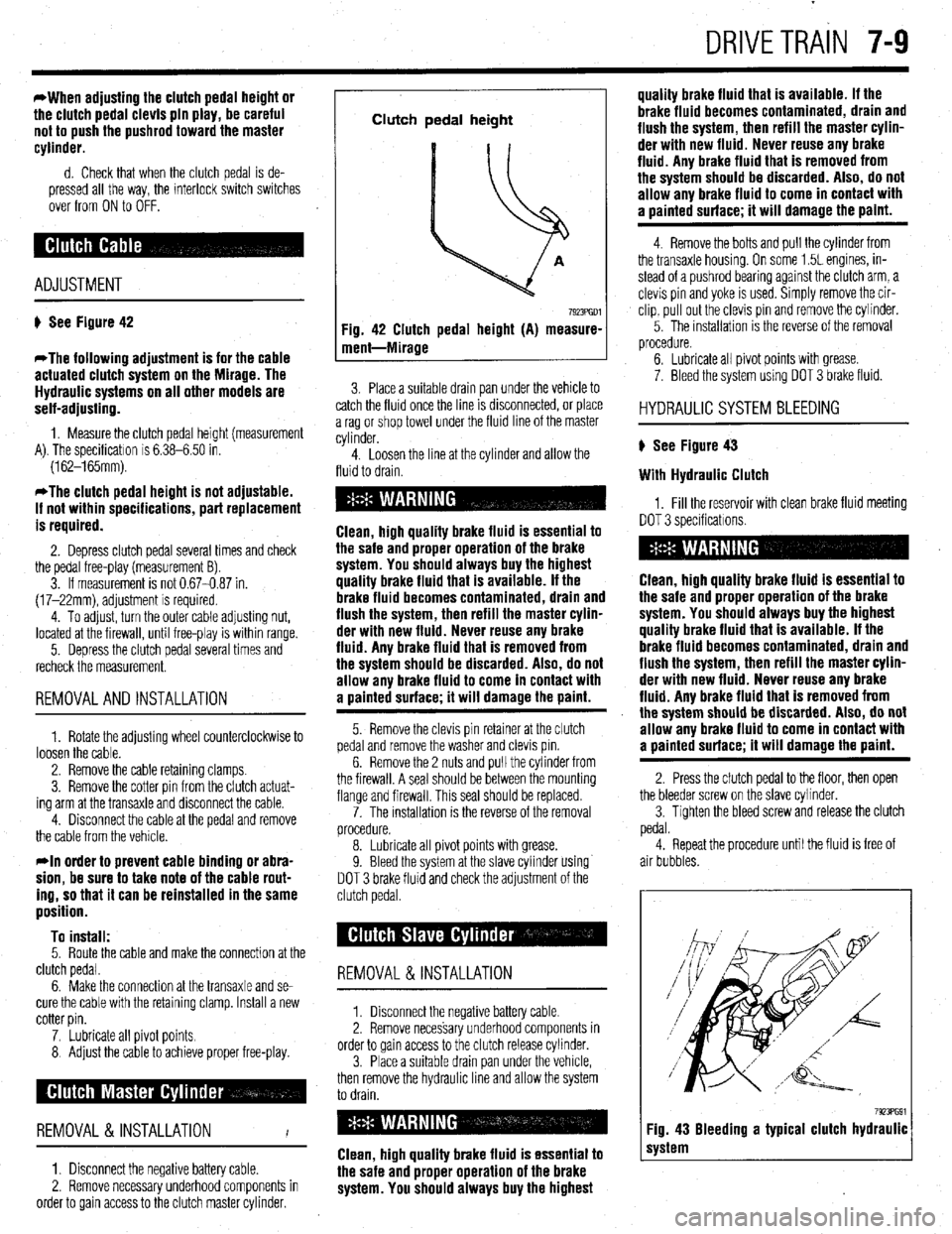
# See Figure 42
*The following adjustment is for the cable
actuated clutch system on the Mirage. The
Hydraulic systems on all other models are
self-adjusting.
1. Measure the clutch pedal height (measurement
A). The specificatron is 6.38-6.50 in.
(162-165mm).
*The clutch pedal height is not adjustable.
If not within specifications, part replacement
is required.
2. Depress clutch pedal several times and check
the pedal free-play (measurement B).
3. If measurement is not 0.67-0.87 in.
(17-22mm), adjustment is required.
4. To adjust, turn the outer cable adjusting nut,
located at the firewall, until free-play is within range.
5. Depress the clutch pedal several times and
recheck the measurement.
REMOVALANDINSTALLATION
1. Rotate the adjusting wheel counterclockwise to
loosen the cable.
2. Remove the cable retaining clamps.
3. Remove the cotter pin from the clutch actuat-
ing arm at the transaxle and disconnect the cable.
4. Disconnect the cable at the pedal and remove
the cable from the vehicle.
rln order to prevent cable binding or abra-
sion, be sure to take note of the cable rout-
ing, so that it can be reinstalled in the same
position.
To install:
5. Route the cable and make the connection at the
clutch pedal.
6. Make the connection at the transaxle and se-
cure the cable with the retaining clamp. Install a new
cotter pin.
7. Lubricate all pivot points.
8 Adjust the cable to achieve proper free-play.
REMOVAL &INSTALLATION
I
1. Disconnect the negative battery cable.
2. Remove necessary underhood components in
order to gain access to the clutch master cylinder.
Clutch pedal height
Fig. 42 Clutch pedal height (A) measure-
ment-Mirage
7923PGDl
3. Place a suitable drain pan under the vehicle to
catch the fluid once the line IS drsconnected, or place
a rag or shop towel under the fluid line of the master
cylinder.
4. Loosen the line at the cylinder and allow the
fluid to drain.
Clean, high quality brake fluid is essential to
the safe and proper operation of the brake
system. You should always buy the highest
quality brake fluid that is available. If the
brake fluid becomes contaminated, drain and
flush the system, then refill the master cylin-
der with new fluid. Never reuse any brake
fluid. Any brake fluid that is removed from
the system should be discarded. Also, do not
allow any brake fluid to come in contact with
a oainted surface; it will damage the paint.
5. Remove the clevis pin retainer at the clutch
pedal and remove the washer and clevis pm.
6. Remove the 2 nuts and pull the cylinder from
the firewall. A seal should be between the mounting
flange and firewall. This seal should be replaced.
7. The installation is the reverse of the removal
procedure.
8. Lubricate all pivot points with grease.
9. Bleed the system at the slave cylinder using
DOT 3 brake fluid and check the adjustment of the
clutch pedal.
REMOVAL &INSTALLATION
1. Disconnect the negative battery cable
2. Remove necessary underhood components in
order to gain access to the clutch release cylinder.
3. Place a suitable drain pan under the vehicle,
then remove the hydraulic line and allow the system
to drain.
Clean, high quality brake fluid is essential to
the safe and proper operation of the brake
system. You should always buy the highest quality brake fluid that is available. If the
brake fluid becomes contaminated, drain and
flush the system, then refill the master cylin-
der with new fluid. Never reuse any brake
fluid. Any brake fluid that is removed from
the system should be discarded. Also, do not
allow any brake fluid to come in contact with
a uainted surface; it will damage the paint.
4. Remove the bolts and pull the cylinder from
the transaxle housing. On some 1.5L engines, in-
stead of a pushrod bearing against the clutch arm, a
clevis pin and yoke is used. Simply remove the cir-
clip, pull out the clevis pin and remove the cylinder.
5. The installation IS the reverse of the removal
procedure.
6. Lubricate all pivot points with grease.
7. Bleed the system using DOT 3 brake fluid.
HYDRAULIC SYSTEM BLEEDING
) See Figure 43
With Hydraulic Clutch
1, Fill the reservoir with clean brake fluid meeting
DOT 3 specificatrons.
Clean, high quality brake fluid is essential to
the safe and proper operation of the brake
system. You should always buy the highest
quality brake fluid that is available. If the
brake fluid becomes contaminated, drain and
flush the system, then refill the master cylin-
der with new fluid. Never reuse any brake
fluid. Any brake fluid that is removed from
the system should be discarded. Also, do not
allow any brake fluid to come in contact with
a painted surface; it will damage the paint.
2. Press the clutch pedal to the floor, then open
the bleeder screw on the slave cvlinder.
3. Tighten the bleed screw and release the clutch
pedal.
4. Repeat the procedure until the fluid is free of
air bubbles.
7923PG91 Fig. 43 Bleeding a typical clutch hydraulic
system
Page 324 of 408
. . . ,.x ..-~ .-....,, _s_s”., .._ ” *
8-28 SUSPENSION AND STEERING
REMOVAL&INSTALLATION
199%93 Mirage 1994-00 Mirage and Galant
b See Figures 76 thru 85 the NEUTRAL mark on the clockspring with the mat-
f ing mark on the casing. Then, install the steering
wheel and tighten the new retaining nut to 29 ft. Ibs.
(40 Nm).
8. Install the air bag module.
1. Disconnect the negative battery cable.
2. Remove the horn pad from the steering wheel,
by pulling the lower end of the pad upward. Detach I
If aqui
arm it --.-.- ---.-...= .-r-.‘- -.. _..- ._.. - -
Failure to do so could result in severe per-
sonal injury and damage to vehicle. pped with an air bag, be sure to dls- hnfnra sfarfinn rmairs on the vehicle.
9. Connect the negative battery cable, turn the key
to the ON position; the SRS warning light should illu-
minate for seven seconds and go out.
1990-93 Galant
hbin butin connector.
3. Remove steering wheel retaining nut:
. . . .‘ .
a. .a I <.
4. Matcnmarlc me steering wneel to me snan.
5. Use a steering wheel puller to remove the
steering wheel.
Do not hammer on steering wheel to remove
it. The collapsible column mechanism may
ha rlsmwmd.
To install:
6. Line up the matchmarks and install the steer-
ing wheel to the shaft.
7. Ti flhten the steering wheel attaching nut to 29
ft. Ibs. (40 Nm).
8. Reconnect the horn connector and install the
horn pad.
9. Connect the neaative battetv cable. 1. Disarm the SRS system as outlined in Section 6.
^ m *I
sand the air bag module
.,A +L. m++-,g w,,eel,
*. I z. Remove me cover
mounting nut from behill” ~IK ~(G~G!I
3. To detach the connector of the clocKsprmfl
from the air bag module, press the air bag’s lock to-
ward the module to spread the lock open. While
holding lock in this position, use a small tipped pry-
ing tool to gently pry the connector from the module.
4. Remove the air bag module and store in a
clean, dry place with the pad cover facing up.
5. Matchmark the steering wheel to the shaft.
6. Remove the steering wheel retaining nut and
use a steering wheel puller to remove the wheel. Do
not use a hammer, or the collapsible mechanism in
the column could be damaged.
To install:
7. Confirm that the front wheels are in a straight-
ahead position. Center the clocksprinfl by aligning 1. Disconnect the negative battery cable.
2. Remove the horn oad from the steerino wheel
as follows:- - - - r d
a. For 1990-91 models only, the horn pad is
removed by pushing the pad upward, to release
the pad from the retaining clips. Detach horn but-
ton connector and remove the pad.
b.
For 1992-93 models only, remove the
screw from the bottom of the pad and push the
pad upward, to release the pad from the retaining
clips. Detach horn button connector and remove
the pad.
3. Remove steering wheel retaining nut.
4. Matchmark the steering wheel to the shaft.
5. Use a steering wheel puller to remove the
steering wheel.
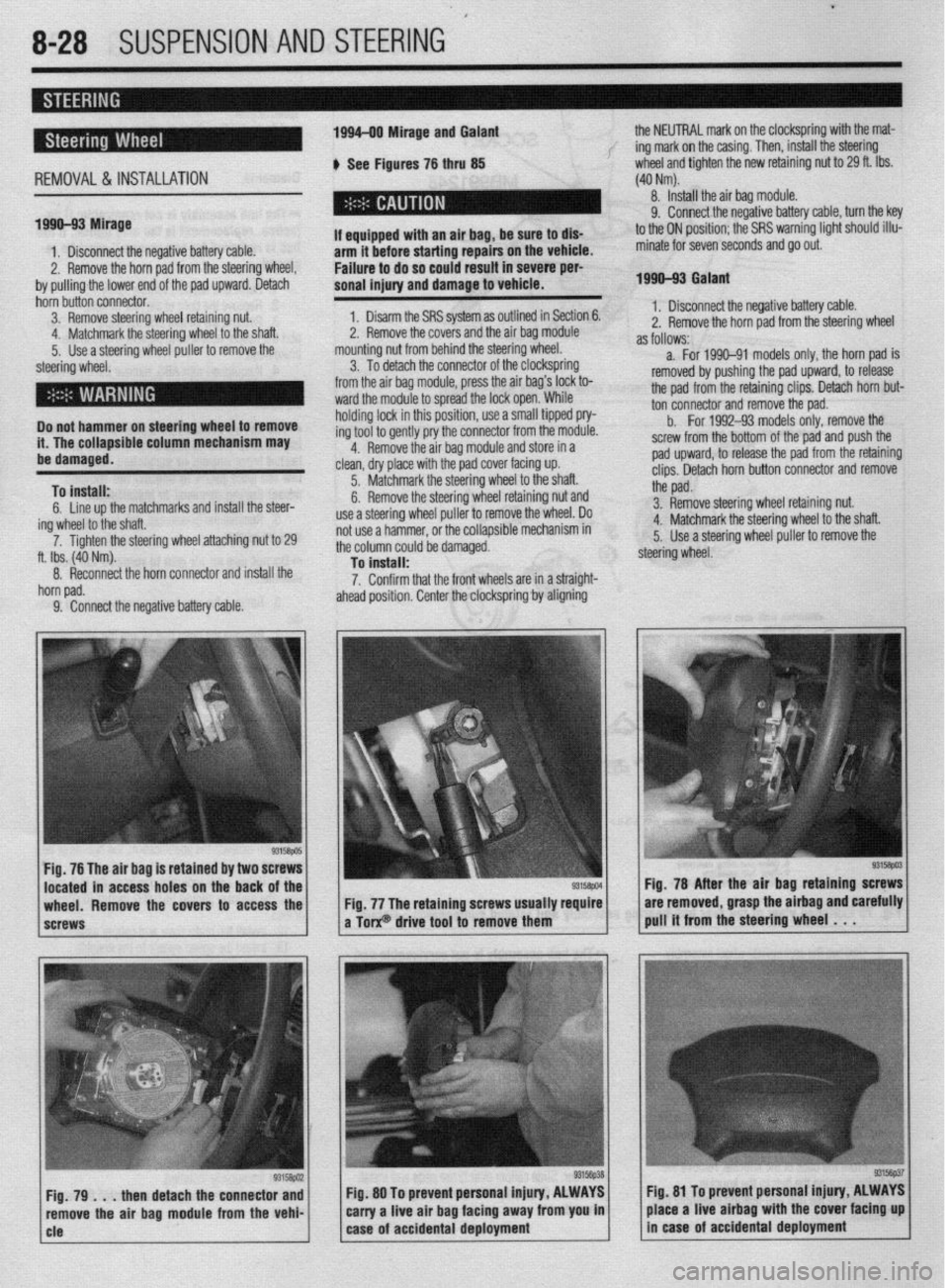
Fig. 76 The air bag is retained by two 8
located in access holes on the back
wheel. Remove the covers to access the
screws Fig. 78 After the air baa
retainino screws
Fig. 77 The retaining screws usually require are removed, grasp the airbag andiarefully
a Torx@ drive tool to remove them pull it from the steering wheel . . .
then detach the connector and Fig. 80 To prevent personal injury, ALWAYS fig. 81 To prevent personal Injury, ALWAYS
ove the air bag module from the vehi- carry a live air bag facing away from you in place a live airbag with the cover facing up
Page 325 of 408
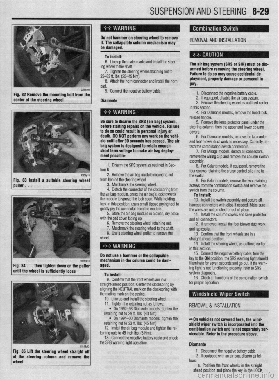
SUSPENSION AND STEERING 8-29
i ’
Do not hamme i4 l-ha nnlhnr !r on steering wheel to remove
,,. , II= ,,,,,,Jfble column mechanism may REMOVALANDINSTALLATION
I
be damaged.
To install:
ing
7.
6. Line up the matchmarks and install the steer-
/heel to the shaft.
Tighten the steering wheel attaching nut to
25-33 ft. Ibs. (35-45 Mm).
8. Attach the horn connector and install the horn
pad.
9. Connect the negative battery cable.
Diamante The air bag system (SRS or SIR) must be dis-
armed before removing the steering wheel.
Failure to do so may cause accidental de-
ployment, property damage or personal in-
MY.
1 Rscnnnnd the nnmtivn hattm rJhle . I._“” . ..I_. . ..I *.-~ _...” ““.‘“‘, _““._. 2. If equipped, disable the air bag system.
3. Remove the steering wheel as outlined earlier
in this section.
Be sure to disarm the SRS (air bag
before starting repairs OI
to do so could result in p
death. DO NOT perform ;
cle until after 90 seconds has passed. The ai
bag system is designed to retain enough
short term voltage to make air bag deploy-
ment possible; I) system,
n the vehicle. Failure
lersonal injury or
any work on the vehi-
ir 4. For Diamante models, remove the hood lock
release handle.
5. Remove the knee protector panel under the
steering column, then the upper and lower column
covers.
6. For Diamante models, remove the lap cooler
and foot blower duct work as necessary. Carefully de-
non
b. 1. Disarm the SRS system as outlined in Sec-
. . ^ I assembly. tach the combination switch connecto&.
8. -
7. For Mirage models, detach all connectors,
For Galant models, if equipped, remove the remove the wiring clip and remove the column switch
2. Remove the air bag module mounting nut
from behind the steering wheel.
3. Matchmark the steering wheel.
4. Detach the connector of the clockspring from
the air baq module, press the air baa’s lock towards four screws retaining the cruise control slip ring to
the switch.
9. For Galant models, remove the two retaining
screws from the combination switch and remove the
switch from the column.
Tn install: the modub to spread the lock open:While holding
lock in this position, use a small tipped prying tool to
gently pry the connector from the module.
5. Store the air bag module in a clean, dry place
..# ,I I I .
ut.
Iaft. wlrn me paa cover racmg up.
6. Remove the steering wheel retaining nl
7. Matchmark the steering wheel to the sl
8. Use a steering wheel puller to remove the
wheel. - . . - _-. . _
10. Install the switch assembly and secure all
harness connectors with clips if needed. Make sure
the wires are not pinched orout of place.
11. Install the column covers and knee protector
and all connectors.
12. If removed, install the foot blower duct work
anfl tan cnnler -..- .-
r --- ”
13. Confirm that the front wheels are in a
straight-ahead position.
14. Install the steering wheel, as outlined earlier
in thir
Do not use a hammer or the ~r”---‘~‘- 15. Connect the negative battery cable, turn the
key to the ON position, the SRS warning light should
NW down
rinntlv
wImpl* the puller
iem Fig. 84 . . . then tighte
until the wheel is suffL,,,,, lVvoV
To install:
0 Pnnfirm that thn frnnt whnalc ,?A in , .I. ““llllllll u,a, ,110 ll”lll I.ll~rJlJ CnIj 111 a
straight-ahead position. Center the clockspring by
aligning the NEUTRAL mark on the clockspring with
the mating mark on the casing.
10. Line up and install the steering wheel. illuminate for seven seconds and go out. If the warn-
ing light is not functioning properly, refer to SRS
s’ .’ ystem cllagnosls.
16. Check all functions of the combination switch
for proper operation.
wheel lows:
a. Position the front wheels in the straight
ahead position and place the key in the LOCK
93158p12 Fig. 85 Lift the steering wheel straight off
of the steering column and remove the 11. Tighten the retaining nut as follows:
REMOVAL &INSTALLATION
l On 1992-93 Diamante models, tighten the
nut to 29 ft. Ibs. (40 Nm) retammg I
l On
retaining I
12. lnstal
taining nuts 1
13. Conn
“... . ..” .‘“J...*.” ‘&.“WSJ Y..“.” . ..rn” VII”“..
the SRS warning light operation. 1994-00 Diamante models, tighten the
iut to 33 ft. Ibs. (45 Nm)
II the air bag module and tighten the r&
:o 48 inch Ibs. (5 Nm).
wt the rwnative hatim rahle ami rhwk
*On vehicles not covered here, the wind-
shield wiper switch is incorporated into the
combination switch and is not separately serl
viceable. Refer to the procedure
above.
Diamante
1. Disconnect the negative battery cable.
2. If equipped with an air bag, disarm as fol-
I” .L
Page 326 of 408
8-30 SUSPENSION AND STEERING
position. Remove the key from the ignition lock
cylinder.
b. Disconnect the negative battery cable and
insulate the cable end with high-quality electrical
tape or similar non-conductive wrapping.
c. Wait at least 1 minute before working on
the vehicle. The air bag system is designed to re-
tain enough voltage to deploy the air bag for a
short period of time even after the battery has
been disconnected.
3. Remove the steering wheel. as outlined ear-
lier in this section.
4. Remove the hood lock release handle.
5. Remove the switches from the knee protector
below the steering column, and remove the exposed
retaining screws. Then remove the knee protector.
6. Remove the column covers.
7. Remove necessary duct work and detach the
windshield wiper switch connectors. +
8. Remove the retaining screws and remove the
windshield wiper switch assembly from the steering
column.
To install: 9. Install the wiper switch to the steering col-
umn and connect the connectors.
IO. Install any removed duct work.
11. Install the column covers.
12. Install the knee protector and switches.
13. Install the hood release handle.
14. Confirm that the front wheels are in a straight
ahead position. Install the steering wheel, as outlined
earlier in this section.
15. Connect the negative battery cable and check
the windshield wiper and washer for proper opera-
tion
REMOVAL &INSTALLATION
The air bag system (SRS or SIR) must be dis-
armed before removing the steering wheel.
Failure to do so may cause accidental de-
ployment, property damage or personal in-
jury.
1. If equipped, properly disarm the air bag sys-
tern:
2. Disconnect the negative battery cable.
3. Remove the hood lock release lever from the
lower panel.
4. Remove the lower instrument panel knee pro-
tector.
5. Remove the ductwork with the lower knee
panel and remove the steering wheel assembly.
Use proper steering wheel puller equipment
when removing the steering wheel. The use
of a hammer for removal could damage the
collapsible mechanism within the column.
6. Remove the lower and upper steering column
covers.
7. For Diamante models, remove the lap cooler
and foot shower duct work.
8. If necessary, remove the clip that holds the
wiring harness against the steering column. 9. Detach all necessary connectors.
10. For Galant and Diamante models, remove the
retaining screws, then remove the entire column
switch/clockspring assembly from the left side of the
steering column.
11. For Diarnante models, remove the mounting
screws from the ignition switch and pull the switch
from the interlock cylinder.
12. Insert the key into the steering lock cylinder
and turn to the
ACC position.
13. With a small, pointed tool, push the lock pin
of the steering lock cylinder inward and pull the lock
cylinder out.
14. Remove the key reminder switch, if equipped.
To install: 15. For Mirage, install the lock cylinder in the
lock cylinder bracket. Make sure the cylinder oper-
ates properly before breaking off the heads of the
special bolts, if the bracket was replaced.
16. For Galant and Diarnante models, install the
lock cylinder into the interlock housing. Be sure the
lock pin snaps into place. Install the ignition switch
into the interlock housing. Align the keyway of the ig-
nition switch with the lock cylinder and secure with
the mounting screws.
17. For Galant and Diamante models, install the
column switch/clockspring assembly to the and con-
nect the harness.
18. install the key reminder switch, if equipped.
19. Attach the harness connections and install
the wiring clip.
20. If removed, install the lap cooler and foot
shower duct work.
21. Install the steering column upper and lower
covers.
22. If necessary, install the knee protector and the
steering wheel.
23. Install the hood lock release lever.
24. Connect the negative battery cable, enable the
air bag system, and check the ignition switch and
lock for proper operation.
REMOVALANDINSTALLATION
Mirage and Galant
I. Disconnect the negative battery cable. If
equipped, disarm the air bag system.
2. Remove the hood lock release lever from the
lower panel.
3. Remove the lower instrument panel knee pro-
tector.
4. Remove the ductwork with the lower knee
panel and remove the steering wheel assembly.
*Use proper steering wheel puller equip-
ment when removing the steering wheel. The
use of a hammer for removal could damage
the collapsible mechanism within the col-
umn.
5. Remove the lower steering column cover.
6. Remove the upper steering column cover.
7. Remove the clip that holds the wiring harness
against the steering column.
8. For Galant models, insert the key into the
steering lock cylinder and turn to the ACC position.
9. For Galant models, using a small pointed
tool, push the lock pin of the steering lock cylinder
inward and pull the lock cylinder out. IO. For Galant models, remove the key reminder
switch, if equipped.
11. Unplug the ignition switch harness connec-
tor. Remove the ignition switch mounting screws and
pull the switch from the steering lock cylinder.
*Vehicles equipped with automatic
transaxle have safety-lock systems and will
have a key interlock cable installed in a slide
lever on the side of the key cyfinder. Care-
fully unhook the interlock cable from the lock
cylinder while withdrawing the cylinder from
the lock housing.
To install:
*To remove the steerlng lock, use a hack-
saw or equivalent to cut the special bolts
through the bracket. The bracket and bolts
must be replaced with new ones.
12. With the ignition key removed, install the
slide lever and the interlock cable to the steering lock
cylinder. Apply grease to the interlock cable and in-
stall the cylinder into the lock housing. Check for
normal operation of the interlock system.
13. Install the ignition switch into the rear of the
lock cylinder housing. Be sure to align the keyway of
the ignition switch with interlock cylinder.
14. Attach the harness connections and install
the wiring clip.
15. Install the steering column upper and lower
covers.
16. Install the knee protector.
17. Connect the negative battery cable, enable the
air
bag system (if equipped) and check the ignition
switch and lock for proper operation.
Diamante
Work MUST NOT be started until at least 90
seconds after the ignition switch is turned to
the LOCK position and the negative battery
cable is disconnected from the battery. This
will allow time for the air bag system backup
power supply to deplete its stored energy
preventing accidental air bag deployment
which could result in unnecessary air bag
system repairs and/or personal injury.
I. Disconnect the negative battery cable.
2. Disarm the air bag system, as outlined in
Section 6.
3. Remove the steering wheel, as outlined ear-
lier in this section.
4. Remove the hood lock release handle.
5. Remove the switches from the knee protector
below the steering column and remove the exposed
retaining screws. Then remove the knee protector.
6. Remove the steering column upper and lower
covers. Use care removing the covers to prevent
breakage of alignment tabs.
7. Remove lap cooler and foot shower
duct work. Detach the ignition switch harness connectors.
8. Remove mounting screws from the ignition
switch and pull switch from interlock cylinder.
To install: 9. Install ignition switch into interlock housing.
Align keyway of ignition switch with lock cylinder and
secure with mounting screws.
IO. Connect the ignition switch electrical harness
Plug.
Page 327 of 408

I
SUSPENSION AND STEERING 8-31
11. Install lap cooler and foot shower duct work.
1.’ Disconnect the negative battery cable. 11.
12. Install the upper and lower steering column Back the tie rod and jam nut out one full turn
2. Remove the wheel and tire assembly. until the reference line is in the same position as be-
covers.
3. Remove the cotter pin and the castellated nut
fore.
13. Install the knee protector and switches.
12. Place the outer tie rod end stud into the steer-
14. Install the hood release handle. from the outer tie rod end. Discard the cotter pin.
4. Separate the outer tie rod end from the steer-
15. Install the steering wheel, as outlined earlier
ing knuckle using an appropriate tie rod end remover. ing knuckle. Set the front wheels in a straight ahead
in this section. position.
16. Connect the negative battery cable and check 5. Mark the outer tie rod jam nut on one side 13. Connect the outer tie rod end to the steering
with a reference line for installation.
all functions of column-mounted switches and the ig-
Hold the outer tie rod end with a wrench and knuckle and install the castle nut. Tighten the nut to
6.
nition switch for proper operation,
loosen the tie rod end jam nut. 25 ft. Ibs. (34 Nm) on Mirage models and 21 ft. Ibs.
(29 Nm) on the Galant and Diamante models.
7. Back the tie rod end jam nut off ONE FULL
TURN ONLY. 14. Continue to tighten the castellated nut until a
new cotter pin can be inserted through the hole in the
8. Remove the outer tie rod end from the inner
REMOVAL&INSTALLATION
Tie Rod Ends tie rod spindle.
To install:
9. Clean the threads on the inner tie rod spindle
(front wheel spindle connecting rod).
10. Thread the new outer tie rod end onto the in- stud. Install a new cotter pin.
15. If required, repeat the procedure for the oppo-
site side,
16. Reinstall the wheel and tire a&embly. Tighten
the lug nuts to 65-80 ft. Ibs. (90-l 10 Nm).
u See Figures 86 thru 94 ner tie rod until it bottoms on the jam nut. 17. Reconnect the negative battery cable.
18. Tighten the tie rod end jam nut to 30 ft. Ibs.
g3’5a~51 Fig. 89 Remove the Be rod end from the
steering knuckle *
Fig. 92 Back the jam nut off ONE TURN OMLY
. * m Fig. 98 . . .
then unthread the tie rod end
Fig. 94 Remove the tie rod end from the ve-
from the inner tie rod
hicle Fig. 88 A special puller is recommended for
removing the tie rod end from the steering
knuckle without damaging the tie rod end
Fig. 91 Use two wrenches, one to hold the
inner tie rod, and one to loosen the jam nut
93158p29
Page 338 of 408
9-2 BRAKES
Hydraulic systems are used to actuate the brakes
of all modern automobiles. The system transports the
power required to force the frictional surfaces of the
braking system together from the pedal to the indi-
vidual brake units at each wheel. A hydraulic system
is used for two reasons.
First, fluid under pressure can be carried to all
parts of an automobile by small pipes and flexible
hoses without taking up a significant amount of room
or posing routing problems.
Second, a great mechanical advantage can be
given to the brake pedal end of the system, and the
foot pressure required to actuate the brakes can be
reduced by making the surface area of the master
cylinder pistons smaller than that of any of the pis-
tons in the wheel cylinders or calipers.
The master cylinder consists of a fluid reservoir
along with a double cylinder and piston assembly.
Double type master cylinders are designed to sepa-
rate the front and rear braking systems hydraulically
in case of a leak. The master cylinder converts me-
chanical motion from the pedal into hydraulic pres-
sure within the lines. This pressure is translated back
into mechanical motion at the wheels by either the
wheel cylinder (drum brakes) or the caliper (disc
brakes).
Steel lines carry the brake fluid to a point on the
vehicle’s frame near each of the vehicle’s wheels. The
fluid is then carried to the calipers and wheel cylin-
ders by flexible tubes in order to allow for suspen-
sion and steering movements.
In drum brake systems, each wheel cylinder con-
tains two pistons, one at either end, which push out-
ward in opposite directions and force the brake shoe
into contact with the drum.
In disc brake systems, the cylinders are part of the
calipers. At least one cylinder in each caliper is used
to force the brake pads against the disc.
All pistons employ some type of seal, usually
made of rubber, to minimize fluid leakage. A rubber
dust boot seals the outer end of the cylinder against
dust and dirt. The boot fits around the outer end of
the piston on disc brake calipers, and around the
brake actuating rod on wheel cylinders.
The hydraulic system operates as follows: When at
rest, the entire system, from the piston(s) in the mas-
ter cylinder to those in the wheel cylinders or
calipers, is full of brake fluid. Upon application of the
brake pedal, fluid trapped in front of the master cylin-
der piston(s) is forced through the lines to the wheel
cylinders. Here, it forces the pistons outward, in the
case of drum brakes, and inward toward the disc, in
the case of disc brakes. The motion of the pistons is
opposed by return springs mounted outside the
cylinders in drum brakes, and by spring seals, in disc
brakes.
Upon release of the brake pedal, a spring located
inside the master cylinder immediately returns the
master cylinder pistons to the normal position. The
pistons contain check valves and the master cylinder
I
has compensating ports drilled in it. These are un-
covered as the pistons reach their normal position.
The piston check valves allow fluid to flow toward the
wheel cylinders or calipers as the pistons withdraw.
Then, as the return springs force the brake pads or
shoes into the released position, the excess fluid
reservoir through the compensating ports. It is during the time the pedal is in the released position that any
fluid that has leaked out of the system will be re-
placed through the compensating ports.
Dual circuit master cylinders employ two pistons,
located one behind the other, in the same cylinder.
The primary piston is actuated directly by mechanical
linkage from the brake pedal through the power
booster. The secondary piston is actuated by fluid
trapped between the two pistons. If a leak develops in
front of the secondary piston, it moves forward until it
bottoms against the front of the master cylinder, and
the fluid trapped between the pistons will operate the
rear brakes. If the rear brakes develop a leak, the pri-
mary piston will move forward until direct contact
with the secondary piston takes place, and it will
force the secondary piston to actuate the front brakes.
In either case, the brake pedal moves farther when the
brakes are applied, and less braking power is avail-
able.
All dual circuit systems use a switch to warn the
driver when only half of the brake system is opera-
tional. This switch is usually located in a valve body
which is mounted on the firewall or the frame below
the master cylinder. A hydraulic piston receives pres-
sure from both circuits, each circuits pressure being
applied to one end of the piston. When the pressures
are in balance, the piston remains stationary. When
one circuit has a leak, however, the greater pressure
in that circuit during application of the brakes will
push the piston to one side, closing the switch and
activating the brake warning light.
In disc brake systems, this valve body also con-
tains a metering valve and, in some cases, a propor-
tioning valve. The metering valve keeps pressure
from traveling to the disc brakes on the front wheels
until the brake shoes on the rear wheels have con-
tacted the drums, ensuring that the front brakes will
never be used alone. The proportioning valve con-
trols the pressure to the rear brakes to lessen the
chance of rear wheel lock-up during very hard brak-
ing.
Warning lights may be tested by depressing the
brake pedal and holding it while opening one of the
wheel cylinder bleeder screws. If this does not cause
the light to go on, substitute a new lamp, make conti-
nuity checks, and, finally, replace the switch as nec-
essary.
The hydraulic system may
be checked for leaks by applying pressure to the pedal gradually and steadily.
If the pedal sinks very slowly to the floor, the system
has a leak. This is not to be confused with a springy
or spongy feel due to the compression of air within
the lines. If the system leaks, there will be a gradual
change in the position of the pedal with a constant
pressure.
Check for leaks along all lines and at wheel cylin-
ders. If no external leaks are apparent, the problem is
inside the master cylinder,
DISC BRAKES
Instead of the traditional expanding brakes that
press outward against a circular drum, disc brake
systems utilize a disc (rotor) with brake pads posi-
tioned on either side of it. An easily-seen analogy is
the hand brake arrangement on a bicycle. The pads
squeeze onto the rim of the bike wheel, slowing its
motion. Automobile disc brakes use the identical principle but apply the braking effort to a separate
disc instead of the wheel.
The disc (rotor) is a casting, usually equipped with
cooling fins between the two braking surfaces. This
enables air to circulate between the braking surfaces
making them less sensitive to heat buildup and more
resistant to fade. Dirt and water do not drastically af-
fect braking action since contaminants are thrown off
by the centrifugal action of the rotor or scraped off
the by the pads. Also, the equal clamping action of
the two brake pads tends to ensure uniform, straight
line stops. Disc brakes are inherently self-adjusting.
There are three general types of disc brake:
1. A fixed caliper.
2. A floating caliper.
3. A sliding caliper.
The fixed caliper design uses two pistons
mounted on either side of the rotor (in each side of
the caliper). The caliper is mounted rigidly and does
not move.
The sliding and floating designs are quite similar.
In fact, these two types are often lumped together. In
both designs, the pad on the inside of the rotor is
moved into contact with the rotor by hydraulic force.
The caliper, which is not held in a fixed position,
moves slightly, bringing the outside pad into contact
with the rotor. There are various methods of attaching
floating calipers. Some pivot at the bottom or top,
and some slide on mounting bolts. In any event, the
end result is the same.
DRUM BRAKES
Drum brakes employ two brake shoes mounted on
a stationary backing plate. These shoes are posi-
tioned inside a circular drum which rotates with the
wheel assembly. The shoes are held in place by
springs. This allows them to slide toward the drums
(when they are applied) while keeping the linings and
drums in alignment. The shoes are actuated by a
wheel cylinder which is mounted at the top of the
backing plate. When the brakes are applied, hydraulic
pressure forces the wheel cylinder’s actuating links
outward. Since these links bear directly against the
top of the brake shoes, the tops of the shoes are then
forced against the inner side of the drum. This action
forces the bottoms of the two shoes to contact the
brake drum by rotating the entire assembly slightly
(known as servo action). When pressure within the
wheel cylinder is relaxed, return springs pull the
shoes back away from the drum.
Most modern drum brakes are designed to self-
adjust themselves during application when the vehi-
cle is moving in reverse. This motion causes both
shoes to rotate very slightly with the drum, rocking
an adjusting lever, thereby causing rotation of the ad-
justing screw. Some drum brake systems are de-
signed to self-adjust during application whenever the
brakes are applied. This on-board adjustment system
reduces the need for maintenance adjustments and
keeps both the brake function and pedal feel satisfac-
tory.
POWER BOOSTERS
Virtually all modern vehicles use a vacuum as-
sisted power brake system to multiply the braking
force and reduce pedal effort. Since vacuum is always
available when the engine is operating, the system is