1900 MITSUBISHI DIAMANTE cooling
[x] Cancel search: coolingPage 74 of 408
ENGINEANDENGINEOVERHAUL 3-13
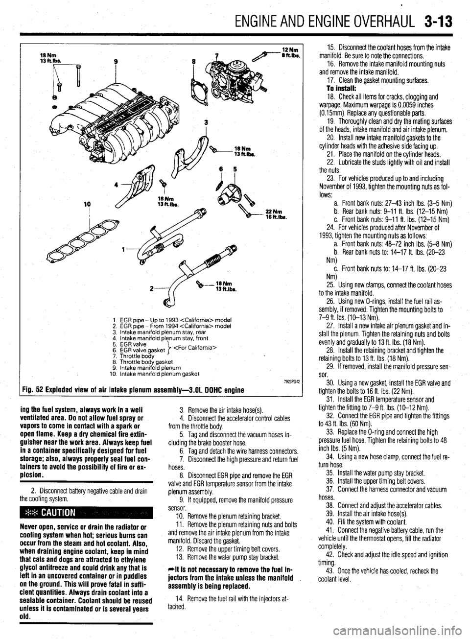
EGR pipe - Up to 1993
EGR pipe - From 1994
Intake manlfold plenum stay, rear
Intake manifold plenum stay. front
EGR valve
EGR valve gasket
Throttle body >
Throttle body gasket
Intake mantfold plenum
Intake manifold plenum gasket
:ig. 52 Exploded view of air intake plenum assembly-3.01 DOHC engine
ing the fuel system, always work in a well
3. Remove the air intake hose(s). ventilated area. Do not allow fuel spray or 4. Disconnect the accelerator control cables vapors to come in contact with a spark or from the throttle body. open flame. Keep a dry chemical fire extin-
guisher near the work area. Always keep fuel
in a container specifically designed for fuel
storage; also, always properly seal fuel con-
tainers to avoid the possibility of fire or ex-
plosion.
2. Disconnect battery negative cable and drawn
the cooling system.
Never open, service or drain the radiator or
cooling system when hot; serious burns can
occur from the steam and hot coolant. Also,
when draining engine coolant, keep in mind
that cats and dogs are attracted to ethylene
glycol antifreeze and could drink any that is
left in an uncovered container or in puddles
on the ground. This will prove fatal in suffi-
cient quantities. Always drain coolant into a
sealable container. Coolant should be reused
unless it is contaminated or is several years
old.
5. Tag and disconnect the vacuum hoses in-
cluding the brake booster hose.
6. Tag and detach the wire harness connectors,
7. Disconnect the high pressure and return fuel
hoses.
8. Disconnect EGR pipe and remove the EGR
valve and EGR temperature sensor from the intake
plenum assembly.
9. If equipped, remove the manifold pressure
sensor.
10. Remove the plenum retaining bracket.
11. Remove the plenum retaining nuts and bolts
and remove the air intake plenum from the intake
manifold. Discard the gasket.
12. Remove the upper timing belt covers.
13. Remove the water pump stay bracket.
*It is not necessav to remove the fuel ln-
jectors from the intake unless the manifold ,
assembly is being replaced.
14. Remove the fuel rail with the injectors at-
tached. 15. Disconnect the coolant hoses from the intake
manifold. Be sure to note the connections.
16. Remove the intake manifold mounting nuts
and remove the intake manifold.
17. Clean the gasket mounting surfaces.
To install: 18. Check all items for cracks, clogging and
warpage. Maximum warpage is 0.0059 inches
(0.15mm). Replace any questionable parts.
19. Thoroughly clean and dry the mating surfaces
of the heads, intake manifold and air intake plenum.
20. Install new intake manifold gaskets to the
cylinder heads with the adhesive side facing up.
21. Place the manifold on the cylinder heads.
22. Lubricate the studs lightly with oil and install
the nuts.
23. For vehicles produced up to and including
November of 1993, tighten the mounting nuts as fol-
lows:
a. Front bank nuts: 27-43 inch Ibs. (3-5 Nm)
b. Rear bank nuts: 9-11 ft. Ibs. (12-15 Nm)
c. Front bank nuts: 9-11 ft. Ibs. (12-15 Nm)
24. For vehicles produced after November of
1993, tighten the mounting nuts as follows:
a. Front bank nuts: 48-72 inch Ibs. (5-8 Nm)
b. Rear bank nuts to: 14-17 ft. Ibs. (20-23
Nm)
c. Front bank nuts to: 14-17 ft. Ibs. (20-23
NM
25. Using new clamps, connect the coolant hoses
to the intake manifold.
26. Using new O-rings, install the fuel rail as-
sembly, if removed. Tighten the mounting bolts to
7-9 ft. Ibs. (10-13 Nm).
27. Install a new intake air plenum gasket and in-
stall the plenum. Tighten the retaining nuts and bolts
evenly and gradually to 13 ft. Ibs. (18 Nm).
28. Install the retaining bracket and tighten the
retaining bolts to 13 ft. Ibs. (18 Nm).
29. If removed, install the manifold pressure sen-
sor.
30. Using a new gasket, install the EGR valve and
tighten the bolts to 16 ft. Ibs. (22 Nm).
31. Install the EGR temperature sensor and
tighten the fitting to 7-9 ft. Ibs. (10-12 Nm).
32. Connect the EGR pipe and tighten the fittings
to 43 ft. Ibs. (60 Nm).
33. Replace the O-ring and connect the high
pressure fuel hose. Tighten the retaining bolts to 48
inch Ibs. (5 Nm).
34. Using a new hose clamp, connect the fuel re-
turn hose.
35. Install the water pump stay bracket.
36. Install the upper timing belt covers.
37. Connect the harness connector and vacuum
hoses.
38. Connect and adjust the accelerator cables.
39. Install the air intake hose(s).
40. Fill the system with coolant.
41. Connect the negative battery cable, run the
vehicle until the thermostat opens, fill the radiator
completely.
42. Check and adjust the idle speed and ignition
timing.
43. Once the vehicle has cooled, recheck the
coolant level.
Page 75 of 408
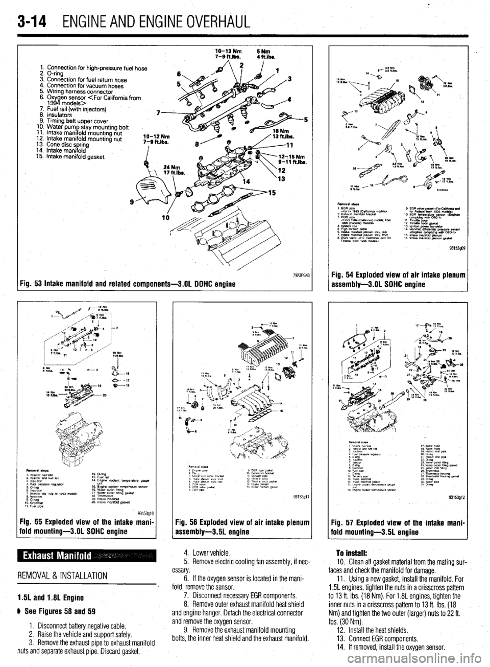
.
3-14 ENGINEANDENGINEOVERHAUL
1. Connection for high-pressure fuel hose
2. O-ring
3. Connection for fuel return hose
4. Connection for vacuum hoses
5. Wrring harness connector
6. Oxy
P en sensor
7. Fuel rail (with injectors)
8 Insulators
9. Timing belt upper cover
10. Water pump stay mountrng bolt
11. Intake manifold mounting nut
12. Intake manifold mounting nut
13 Cone disc spring
14. Intake manrfold
15. intake manifold gasket
:ig. 53 Intake manifold and related components-3.01 DDHC enaine
Fig. 55 Exploded view of the intake mani- :ig. 56 Exploded view of
fold mounting-3.01 SDHC engine
Issembly-3.5L engine air intake plenum
5. Remove electric cooling fan assembly, if nec- 4. Lower vehicle. To install: 10. Clean all gasket material from the mating sur-
REMOVAL &INSTALLATION
1.5L and 1.8L Engine
# See Figures 58 and 59 essary. faces and check the manifold for damage.
6. If the oxygen sensor is located in the mani- 11. Using a new gasket, install the manifold. For
fold, remove the sensor. 1.5L engines, tighten the nuts in a crisscross pattern
7. Disconnect necessary EGR components. to 13 ft. Ibs. (18 Nm). For 1.8L engines, tighten the
8. Remove outer exhaust manifold heat shield inner nuts in a crisscross pattern to 13 ft. Ibs. (18
and engine hanger. Detach the electrical connector Nm) and tighten the two outer (larger) nuts to 22 ft.
1. Disconnect battery negative cable.
2. Raise the vehicle and support safely
3. Remove the exhaust pipe to exhaust manifold
nuts and separate exhaust pipe. Discard gasket, and remove the oxygen sensor.
9. Remove the exhaust manifold mounting
bolts, the inner heat shield and the exhaust manifold. Ibs. (30 Nm).
12. Install the heat shields,
13. Connect EGR components.
14. If removed, install the oxygen sensor.
Page 76 of 408
ENGlNEANDENGlNEOVERHAbL 3-15
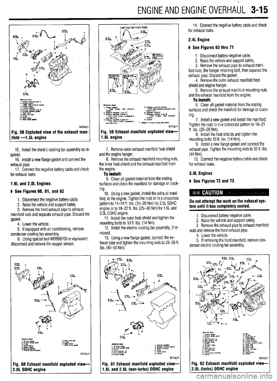
Fig. 58 Exploded view of the exhaust man,
ifold -1.5L enoine
15. Install the electric cooling fan assembly as re-
quired.
16. Install a new flange gasket and connect the
exhaust pipe.
17. Connect the negative battery cable and check
for exhaust leaks.
1.8L and 2.OL Engines
u See Figures 80, 81, and 62
1. Disconnect the negative battery cable.
2. Raise the vehicle and support safely.
3. Remove the front exhaust pipe to exhaust
manifold nuts and separate exhaust pipe. Discard the
gasket.
4. Lower the vehicle.
5. If equipped with air conditioning, remove
condenser cooling fan assembly.
6. Using special tool MD998703 or equivalent,
disconnect and remove the oxygen sensor.
:z**
::EEWl
93153915
:ig. 60 Exhaust manifold exploded view-
!.OL SOHC engine
93153g1 Fig. 59 Exhaust manifold exploded vlew-
1.8L engine
7. Remove outer exhaust manifold heat shield
and the engine hanger.
8. Remove the exhaust manifold mounting nuts,
the inner heat shield and the exhaust manifold from
the engine.
To install: 9. Clean all gasket material from the mating
surfaces and check the manifold for damage or crack-
ing.
10. Using a new gasket, install the exhaust mani-
fold, to the engine. Tighten the nuts to in a crrsscross
pattern to 11-14 ft Ibs. (15-20 Nm) for 2.OL SOHC
engine or to 18-22 ft. Ibs. (25-30 Nm) for 1.6L and
2.OL DOHC engine.
11. Install the outer heat shield and tighten the
mounting bolts to 10 ft. Ibs. (14 Nm).
12. Install the electric cooling fan assembly, if re-
moved.
13. Using a new flange gasket, connect the ex-
haust pipe and tighten the mounting nuts to 29-36 ft.
Ibs. (40-50 Nm).
:ig. 81 Exhaust manifold exploded view-
I .8L and 2.OL (non-turbo) DOHC engine
14. Connect the negative battery cable and check
for exhaust leaks.
2.4L Engine
g See Figures 63 thru 71
1, Disconnect battery negative cable.
2. Raise the vehicle and support safely.
3. Remove the exhaust pipe-to-exhaust mani-
fold nuts, the hanger retaining bolt, then separate the
exhaust pipe. Discard the gasket.
4. Remove the outer exhaust manifold heat
shield and engine hanger.
5. Remove the exhaust manifold mounting nuts
and the exhaust manifold from the engine.
To install: 6. Clean all gasket material from the mating
surfaces and check the manifold for damage or crack-
ing.
7. Install a new gasket and install the manifold.
Tighten the nuts to in a crisscross pattern to 18-21
ft Ibs. (25-29 Nm).
8. Install the heat shields and tighten the
mounting bolts IO ft Ibs. (14 Nm).
9. Install a new flange gasket and connect the
exhaust pipe. Tighten the mounting nuts to 32 ft. Ibs.
(44 Nm).
10. Connect the negative battery cable and check
for exhaust leaks.
3.OL Engines
) See Figures 72 and 73
Do not attempt the work on the exhaust sys-
tem until it has completely cooled.
1. Disconnect battery negative cable.
2. Raise the vehicle and support safely.
3. Remove the exhaust pipe to exhaust manifold
nuts and remove the front exhaust pipe.
4. Lower the vehicle.
5. If removing the front manifold, remove con-
denser electric cooling fan assembly.
9315391; -ig. 82 Exhaust manifold exploded view-
!.OL (turbo) DOHC engine
Page 77 of 408
3-16 ,ENGlNEANDENGlNEOVERHAUL
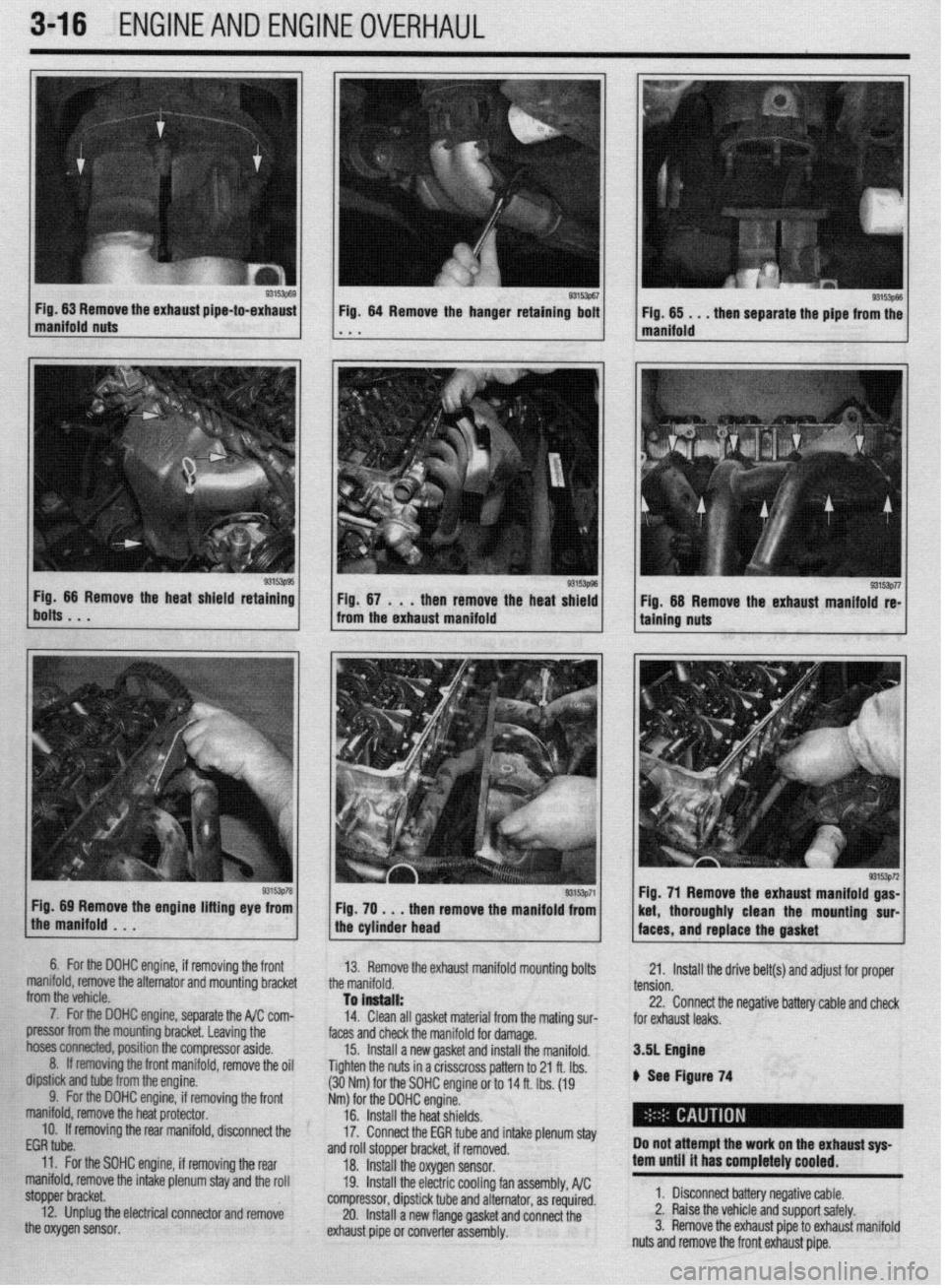
Fig 66 Remove the heat shield retaining
bolts. . . g3’~‘51 Fig. 64 Remove the hanger retaining bolt
* . I(
Fig, 67 . . .
then remove the heat shield
from the exhaust manifold
Fig. 69 Remove the engine lifting eye from
the manifold . . . Fig. 70 , . . then remove the manifold from
the cylinder head Fig. 71 Remove the exhaust manifold gas-
/ faces, and replace the gasket ’ 93’53p72 ket, thoroughly clean the mountmg sur-
6. For the DOHC engine, if removing thr
a front
manifold, remove the alternator and mountin!
from the vehicle. 3 bracket
7. For the DOHC engine, separate the I$,, I.vIII- /r nnm
pressor from the mounting bracket. Leaving the
hoses ~~~, position the compressor aside,
8. ff removing the front manifold, remove the oil
dipstick and tube from the engine.
9. For the DOHC engine, if removing the front
manifold, remove the heat protector. 13. Remove the exhaust manifold mounting bolts
the manifold.
To install:
-4” PI,*, -11 rm.A.^L -,‘&^-:-I f-e.- IL- -_-I!-- - .-
17. lrlMll dll yWK1 Illdlell~l 110111 LIle lKWi~ SIN- faces and check the manifold for damage.
15. Install a new gasket and install the manifold.
Tighten the nuts in a crisscross pattern to 21 ft. Ibs.
(30Nm). .’ --.._
Nm) for 1
16. II 21. Install the drive belt(s) and adjust for proper
tension.
to1 the SOHC engine or to 14 ft. Ibs. (19
he DOHC engine.
Wall the heat shields. 22. Connect the negative battery cable and check
I- L- L, #
ror exnausr leaks.
3.51 Engfne
A Sam Finnwn 74
17. c
“IIII”“IUI” L”ll L”“““ll” IIIlu#lb p,““l~,aa~
and roll stopper bracket, if removed.
18. Install the oxygen sensor.
19. Install the electric cooling fan assembly, A/C
compressor, dipstick tube and alternator, as required.
20. Install a new flange gasket and connect the
exhaust pipe or converter assembly. Do not attempt the work on the
exhaust sys-
tern until it has completely coo
led.
1. Disconnect battery negative cable.
2. Raise the vehicle and support safely.
3. Remove the exhaust pipe to exhaust manifold
nuts and remove the front exhaust pipe. IO. If removing the rear manifold, disconnect the
EGR tube.
11. For the SOHC engine, if removing the rear
manifold, remove the intake plenum stay and the roll
stopper bracket.
12. Unplug the electrical connector and remove
the oxygen sensor.
Page 78 of 408
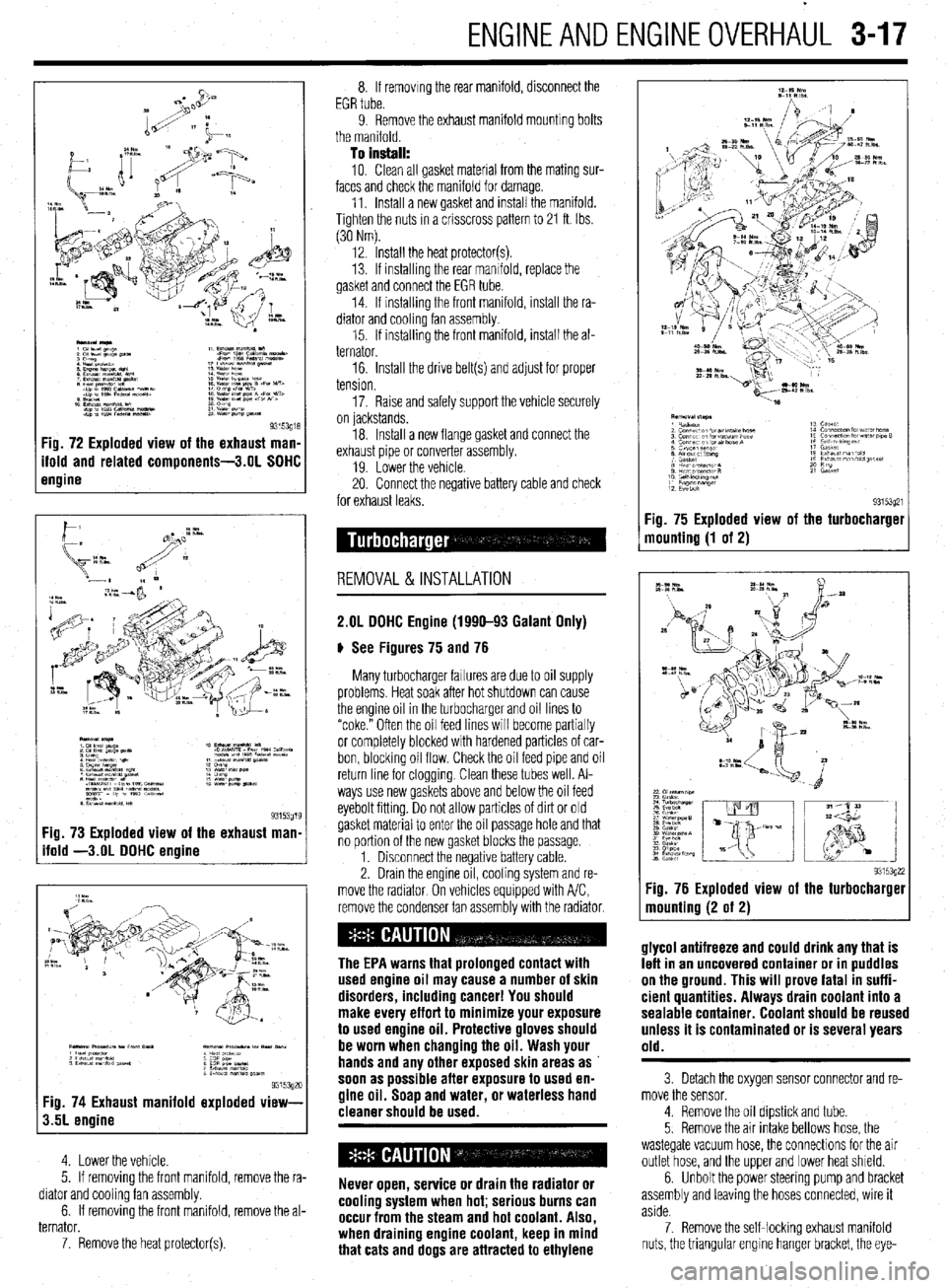
ENGlNEANDENGlNEOVERHAiJL 3-17
Fig. 73 Exploded view of the exhaust man
ifold -3.OL DOHC engine
9315392c Fig. 74 Exhaust manifold exploded view-
3.5L engine
4. Lower the vehicle.
5. If removing the front manifold, remove the ra-
diator and cooling fan assembly.
6. If removing the front manifold, remove the al-
ternator.
7. Remove the heat protector(s). 8. If removing the rear manifold, disconnect the
EGR tube.
9. Remove the exhaust manifold mounting bolts
the manifold.
To install:
10. Clean all gasket material from the mating sur-
faces and check the manifold for damage.
11. Install a new gasket and install the manifold.
Tighten the nuts in a crisscross pattern to 21 ft. Ibs.
(30 Nm).
12. Install the heat protector(s).
13. If installrng the rear manifold, replace the
gasket and connect the EGR tube.
14. If installing the front manifold, install the ra-
diator and cooling fan assembly.
15. If installing the front manifold, install the al-
ternator.
16. Install the drive belt(s) and adjust for proper
tension.
17. Raise and safely support the vehicle securely
on lackstands.
18. Install a new flange gasket and connect the
exhaust pipe or converter assembly.
19 Lower the vehicle
20. Connect the negative battery cable and check
for exhaust leaks.
REMOVAL&INSTALLATION
2.OL DOHC Engine (1990-93 Galant Only)
# See Figures 75 and 76
Many turbocharger failures are due to oil supply
problems. Heat soak after hot shutdown can cause
the engine oil in the turbocharger and oil lines to
“coke.” Often the oil feed lines will become partially
or completely blocked with hardened particles of car-
bon, blocking oil flow. Check the oil feed pipe and oil
return line for cloggrng. Clean these tubes well. Al-
ways use new gaskets above and below the oil feed
eyebolt fitting. Do not allow particles of dirt or old
gasket material to enter the oil passage hole and that
no portion of the new gasket blocks the passage.
1. Disconnect the negative battery cable.
2. Drain the engine oil, cooling system and re-
move the radiator On vehicles equipped with A/C,
remove the condenser fan assembly with the radiator.
The EPA warns that prolonged contact with
used engine oil may cause a number of skin
disorders, including cancer! You should
make every effort to minimize your exposure
to used engine oil. Protective gloves should
be worn when changing the oil. Wash your
hands and any other exposed skin areas as
soon as possible after exposure to used en-
gine oil. Soap and water, or waterless hand
cleaner should be used.
Never open, service or drain the radiator or
cooling system when hot; serious burns can
occur from the steam and hot coolant. Also,
when draining engine coolant, keep in mind
that cats and dogs are attracted to ethylene Fig. 75 Exploded view
mounting (1 of 2)
93153q21 the turbocharget
9315392: :ig. 76 Exploded view of the turbocharger
nounting (2 of 2)
glycol antifreeze and could drink any that is
left in an uncovered container or in puddles
on the ground. This will prove fatal in suffi-
cient quantities. Always drain coolant into a
sealable container. Coolant should be reused
unless it is contaminated or is several years
old.
3 Detach the oxygen sensor connector and re-
move the sensor.
4. Remove the oil dipstick and tube.
5. Remove the air intake bellows hose, the
wastegate vacuum hose, the connections for the air
outlet hose, and the upper and lower heat shield.
6. Unbolt the power steering pump and bracket
assembly and leaving the hoses connected, wire it
aside.
7. Remove the self-locking exhaust manifold
nuts, the triangular engrne hanger bracket, the eye-
Page 79 of 408
l
3-18 ENGINEANDENGINEOVERHAUL
bolt and gaskets that connect the oil feed line to the
turbo center section and the water cooling lines. The
water line under the turbo has a threaded connection.
8. Remove the exhaust pipe nuts and gasket and
lift off the exhaust manifold. Discard the gasket,
9. Remove the 2 through bolts and 2 nuts that 16. If removed, install the power steering pump
and bracket.
17. Install the heat shields, air outlet hose, waste-
gate hose and air intake bellows.
18. Install the oil dipstick tube and dipstick. In-
stall the oxyqen sensor. cient quantities. Always drain coolant into a
sealable container. Coolant should be reused
unless it is contaminated or is several years
old.
3. Disconnect the overflow tube. Some vehicles
hold the exhaust manifold to the turbocharger,
10. Remove the 2 capscrews from the oil return
line (under the turbo). Discard the gasket. Separate
the turbo from the exhaust manifold. The 2 water
pipes and oil feed line can still be attached. 19. In&h the radiator assembly.
20. Fill the engine with oil, fill the cooling system
and reconnect the negative battery cable.
11. Visually check the turbine wheel (hot side)
and compressor wheel (cold side) for cracking or
other damage. Check whether the turbine wheel and
the compressor wheel can be easily turned by hand.
Check for oil leakaae. Check whether or not the Operating the engine without the proper
amount and type of engine oil will result in
severe engine damage.
wastegate valve remains open. If any problem is .
found, replace the part. Inspect oil passages for re- #I , I
striction or deposits and clean as required,
12. The wasteaate can be checked with a ores-
REMOVAL & INSTALLATION sure tester. Apply approximately 9 psi to the&h&or
and make sure the rod moves. Do not apply more
than 10.3 psi or the diaphragm in the wastegate may
be damaged. Vacuum applied to the wastegate actua-
tor should be maintained, replace if leaks vacuum,
Do not attempt to adjust the wastegate valve. $ See Figures 77 thru 91
I. Disconnect the negative battery cable.
2. Drain the cooling system when safe.
To
install: 13. Prime the oil return line with clean engine oil.
Replace all locking nuts. Before installing the
threaded connection for the water inlet pipe, apply
light oil to the inner surface of the pipe flange. As-
semble the turbocharger and exhaust manifold.
14. Install the exhaust manifold using a new gas-
ket.
15. Connect the water cooling lines, oil feed line
and engine hanger. Never open, service or drain the radiator or
cooling system when hot: serious burns can
occur from the steam and hot coolant. Also,
when draining engine coolant, keep in mind
that cats and dogs are attracted to ethylene
glyeol antifreeze and could drink any that is
left in an uncovered container or in puddles
on the ground. This will prove fatal in suffi-
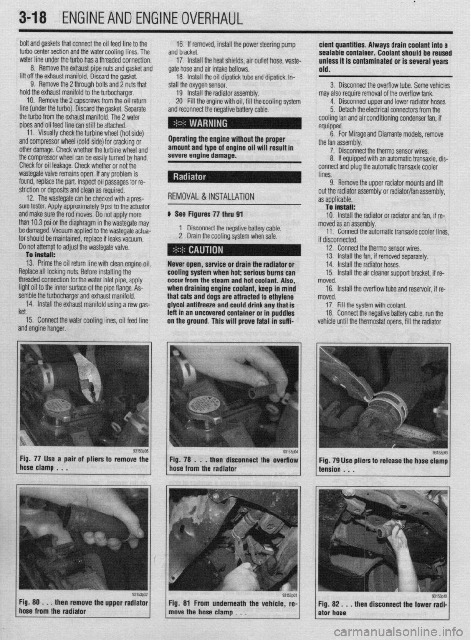
Fig. 77 Use a pair of pliers to remove the
Fig. 78 . . .
then disconnect the overflow
hose clamp . . .
hose from the radiator may also require removal of the overflow tank.
4. Disconnect upper and lower radiator hoses.
5. Detach the electrical connectors from the
cooling fan and air conditioning condenser fan, if
equipped.
6. For Mirage and Diamante models, remove
the fan assembly.
7. Disconnect the therm0 sensor wires,
8. If equipped with an automatic transaxle, dis-
connect and plug the automatic transaxle cooler
lines.
9. Remove the upper radiator mounts and lift
out the radiator assembly or radiator/fan assembly,
as applicable.
To install:
10. Install the radiator or radiator and fan, if re-
moved as an assembly.
11. Connect the automatic transaxle cooler lines
if disconnected.
12. Connect the therm0 sensor wires,
13. Install the fan, if removed separately.
14. Install the radiator hoses.
15. Install the air cleaner support bracket, if re-
noved.
16. Install the overflow tube and reservoir, if re-
noved.
17. Fill the system with coolant.
18. Connect the negative battery cable, run the
vehicle until the thermostat opens, fill the radiator
93153003 Fig. 79 Use pliers to release the hose clamp
tension . . .
Fig. 80 . . .
then remove the upper radiator
hose from the radiator Fig. 81 From underneath the vehicle, re-
move the hose clamp , . . ”
then disconnect the lower radi- Fig. 82 . . .
ator hose
Page 81 of 408
.
3-20 ENGINEANDENGINEOVERHAUL
Never open, service or drain the radiator or
cooling system when hot; serious burns can
occur from the steam and hot coolant. Also,
when draining engine coolant, keep in mind
that cats and dogs are attracted to ethylene
glycol antifreeze and could drink any that is
left in an uncovered container or in puddles
on the ground. This will prove fatal in suffi-
cient quantities. Always drain coolant into a
sealable container. Coolant should be reused
unless it is contaminated or is several years
old.
3. Remove the overflow hose and disconnect
the upper radiator hose.
*It is recommended that each clamp be
matchmarked to the hose. Observe the marks
and reinstall the clamps exactly when rein-
stalling the radiator.
4. If equipped with an automatic transaxle, re-
move and plug the fluid cooler hoses.
5. Unplug the electrical connector(s) from the
coolant fan motor.
6. Remove the mounting bolts, then remove the
fan and shroud assembly from the vehicle.
7. Remove the fan blade retainer nut from the
shaft on the fan motor and separate the fan from the
motor.
8. Remove the motor to shroud attaching
screws and the motor from the shroud.
To tnstall: 9. Install the motor to the shroud and secure
with the mounting bolts.
10. Install the remaining components in the re-
verse order of removal.
11. Fill the coohng system. Connect the negative
battery cable and check the cooling fan for proper op-
eration.
Diamante
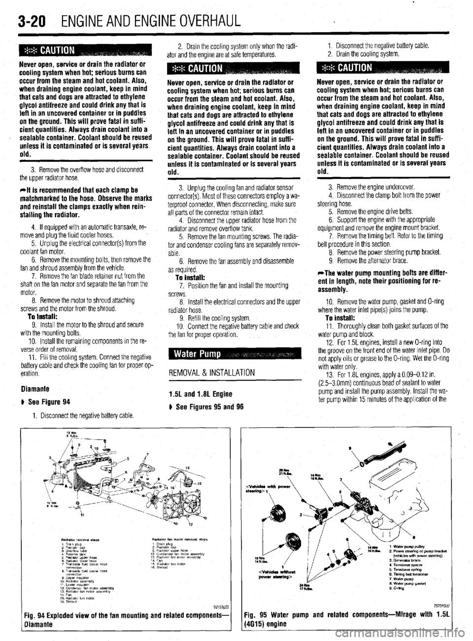
# See Figure 94
1. Disconnect the negative battery cable 2. Drain the cooling system only when the radi-
ator and the engine are at safe temperatures. 1. Disconnect the negative battery cable
2. Drain the cooling system.
Never open, service or drain the radiator or
cooling system when hot; serious burns can
occur from the steam and hot coolant. Also,
when draining engine coolant, keep in mind
that cats and dogs are attracted to ethylene
glycol antifreeze and could drink any that is
left in an uncovered container or in puddles
on the ground. This will prove fatal in suffi-
cient quantities. Always drain coolant into a
sealable container. Coolant should be reused
unless it is contaminated or is several years
old.
3. Unplug the cooling fan and radiator sensor
connector(s). Most of these connectors employ a wa-
terproof connector. When disconnecting, make sure
all parts of the connector remain intact.
4. Disconnect the upper radiator hose from the
radiator and remove overflow tank.
5. Remove the fan mounting screws. The radia-
tor and condenser cooling fans are separately remov-
able.
6. Remove the fan assembly and disassemble
Never open, service or drain the radiator or
cooling system when hot; serious burns can
occur from the steam and hot coolant. Also,
when draining engine coolant, keep in mind
that cats and dogs are attracted to ethylene
glycol antifreeze and could drink any that is
left in an uncovered container or in puddles
on the ground. This will prove fatal in suffi-
cient quantities. Always drain coolant into a
sealable container. Coolant should be reused
unless it is contaminated or is several years
old.
3. Remove the engine undercover.
4 Disconnect the clamp bolt from the power
steering hose.
5. Remove the engine drive belts.
6. Support the engine with the appropriate
equipment and remove the engine mount bracket.
7. Remove the timing belt Reier to the timing
belt procedure in this section
8 Remove the power steering pump bracket.
9. Remove the alternator brace.
as required.
To install: 7. Posrtion the fan and install the mounting
screws
*The water pump mounting bolts are differ-
ent in length, note their positioning for re-
assembly.
8 Install the electrical connectors and the upper
radiator hose.
9. Refill the cooling system.
IO. Connect the negative battery cable and check
the fan for orooer ooeration. 10. Remove the water pump, gasket and O-ring
where the water inlet pipe(s) joins the pump.
To install: 11, Thoroughly clean both gasket surfaces of the
water oumo and block.
12. For 1.5L engines, install a new O-ring into
the groove on the front end of the water inlet pipe. Do
not apply oils or grease to the O-ring. Wet the O-ring
with water only
13. For 1.8L engines, apply a 0.09-0.12 in.
(2.5-3 Omm) continuous bead of sealant to water
pump and rnstall the pump assembly. Install the wa-
ter pump within 15 minutes of the applrcation of the
REMOVAL & INSTALLATION
1.5L and 1.8L Engine
) See Figures 95 and 98
7923PGO :ig. 94 Exploded view of the fan mounting and related components- Fig. 95 Water pump and related components-Mirage with 1.51
liamante (4615) engine
Page 82 of 408
ENGINEANDENGINEOVERHAUL 3-21
7923PG08
ealant. Wait 1 hour after installation of the water
pump to refill the cooling system or start the engine.
14. Install the gasket and pump assembly and
tighten the bolts to 17 ft. Ibs. (24 Nm). Use care when
aligning the water pump with the water inlet pipe.
15. Install the remaining components in the re-
verse order of removal.
16. Fill the system with coolant. 17. Connect the negative battery cable, run the
vehicle until the thermostat opens and fill the radiator
completely.
18. Once the vehicle has cooled, recheck the
coolant level.
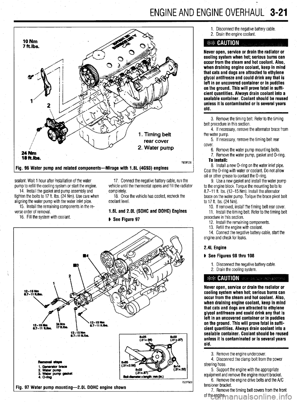
1.6L and 2.OL (SOHC and OOHC) Engines
+ See Figure 97
Fig
1. Disconnect the negative battery cable.
2. Drain the engine coolant.
Never open, service or drain the radiator or
cooling system when hot; serious burns can
occur from the steam and hot coolant. Also,
when draining engine coolant, keep in mind
that cats and dogs are attracted to ethylene
glycol antifreeze and could drink any that is
left in an uncovered container or in puddles
on the ground. This will prove fatal in suffi-
cient quantities. Always drain coolant into a
sealable container. Coolant should be reused
unless it is contaminated or is several years
old.
3. Remove the timing belt. Refer to the timing
belt procedure in this section.
4. If necessary, remove the alternator brace from
the water pump.
5. If necessary, remove the timing belt rear
cover.
6. Remove the water pump mounting bolts.
7. Remove the water pump, gasket and O-ring.
To Install: 8. Install a new O-ring on the water inlet pipe.
Coat the O-ring with water or coolant. Do not allow
oil or other grease to contact the O-ring.
9. Use a new gasket and install the water pump
to the engine block Torque the mounting bolts to
8.7-11 ft. Ibs. (12-15 Nm). Install the alternator
brace on the water pump. Torque the brace pivot bolt
to 17 ft. Ibs. (24 Nm).
10. If removed, install the timing belt rear cover.
11. Install the timing belt. Refer to the timing belt
procedure in this section.
12. Install the remaining components.
13. Refill the engine with coolant.
14. Connect the negative battery cable, start the
engine and check for leaks.
2.4L Engine
) See Figures 98 thru 108
1. Disconnect the negative battery cable
2. Drain the cooling system.
Never open, service or drain the radiator or
cooling system when hot; serious burns can
occur from the steam and hot coolant. Also,
when draining engine coolant, keep in mind
that cats and dogs are attracted to ethylene
glycol antifreeze and could drink any that is
left in an uncovered container or in puddles
on the ground. This will prove fatal in suffi-
cient quantities. Always drain coolant into a
sealable container. Coolant should be reused
unless it is contaminated or is several years
old.
3. Remove the engine undercover.
4. Disconnect the clamp bolt from the power
steering hose.
5 Support the engine with the appropriate
equipment and remove the engine mount bracket.
6. Remove the engine drive belts and the A/C
tensioner bracket.
7. Remove the timing belt covers from the front
of the engine.