2024 FORD F650/750 tires
[x] Cancel search: tiresPage 9 of 386

Cleaning the Interior..................................265
Cleaning the Instrument Panel andInstrument Cluster Lens......................266
Repairing Minor Paint Damage.............266
Cleaning the Wheels.................................266
Vehicle Storage............................................267
Wheels and Tires
Tire Care.........................................................269
Using Snow Chains....................................287
Changing a Road Wheel..........................287
Technical Specifications.........................289
Capacities and Specifications
Engine Specifications - 6.7L Diesel.......291
Engine Specifications - 7.3L....................292
Motorcraft Parts - 6.7L Diesel................293
Motorcraft Parts - 7.3L..............................295
Bulb Specification Chart.........................296
Engine Oil Capacity and Specification -6.7L Diesel.................................................296
Engine Oil Capacity and Specification -7.3L...............................................................299
Cooling System Capacity andSpecification - 6.7L Diesel...................301
Cooling System Capacity andSpecification - 7.3L................................302
Fuel Tank Capacity - Diesel....................303
Fuel Tank Capacity - Gasoline..............304
Air Conditioning System Capacity andSpecification - 6.7L Diesel..................305
Air Conditioning System Capacity andSpecification - 7.3L................................306
Washer Fluid Specification....................306
Diesel Exhaust Fluid Capacity andSpecification............................................307
Automatic Transmission Fluid Capacityand Specification - Diesel...................307
Automatic Transmission Fluid Capacityand Specification - Gasoline.............308
Brake Fluid Specification........................309
Rear Axle Fluid Capacity andSpecification - Diesel...........................309
Rear Axle Fluid Capacity andSpecification - Gasoline.........................311
Hydraulic Power Steering Fluid Capacityand Specification.....................................312
Vehicle Identification
Vehicle Identification Number................313
Connected Vehicle
Connected Vehicle Requirements.........314
Connected Vehicle Limitations..............314
Connecting the Vehicle to a MobileNetwork.......................................................314
Connected Vehicle – Troubleshooting.........................................................................314
Audio System
General Information...................................315
Audio Unit.......................................................315
Connecting a Bluetooth® Device..........318
Streaming Bluetooth Audio.....................318
Playing Media From a USB Device........318
Audio Input Jack...........................................319
USB Port........................................................320
Using Voice Recognition..........................320
Accessories
Auxiliary Switches.......................................321
Ford Protect
Ford Protect..................................................323
Scheduled Maintenance
General Maintenance Information.......325
Normal Scheduled Maintenance.........330
Special Operating Conditions ScheduledMaintenance............................................335
5
2024 F-650/750 (TBC) , enUSA, Edition date: 202210, First-PrintingTable of Contents
Page 62 of 386

Note:Using much larger tires or equippingvehicle accessories such as snowplows canmodify your vehicle's ride height anddegrade automatic high beam controlperformance.
A camera sensor, centrally mountedbehind the windshield of your vehicle,continuously monitors conditions to turnthe high beams on and off.
Once the system is active, the high beamsturn on if:
•The ambient light level is low enough.
•There is no traffic in front of yourvehicle.
•The vehicle speed is greater thanapproximately 32 mph (51 km/h).
The system turns the high beams off if:
•The ambient light level is high enoughthat high beams are not required.
•The system detects an approachingvehicle's headlamps or tail lamps.
•The vehicle speed falls belowapproximately 27 mph (44 km/h).
•The system detects severe rain, snowor fog.
•The camera is blocked.
Switching the System On and Off
Switch the system on using the informationdisplay. See Information Displays (page71).
Switch the lighting control to theautolamps position. See Autolamps(page 56).
Overriding the System
Push the lever away from you to switchbetween high beam and low beam.
Automatic High Beam Indicator
The indicator illuminates toconfirm when the system isready to assist.
DIRECTION INDICATORS
Push the lever up or down to usethe direction indicators.
Note:Tap the lever up or down to make thedirection indicators flash three times.
INTERIOR LAMPS
The lamps turn on under the followingconditions:
•You open any door.
•You press a remote control button.
58
2024 F-650/750 (TBC) , enUSA, Edition date: 202210, First-PrintingLightingE142451 E146105 E311431 E67018
Page 139 of 386
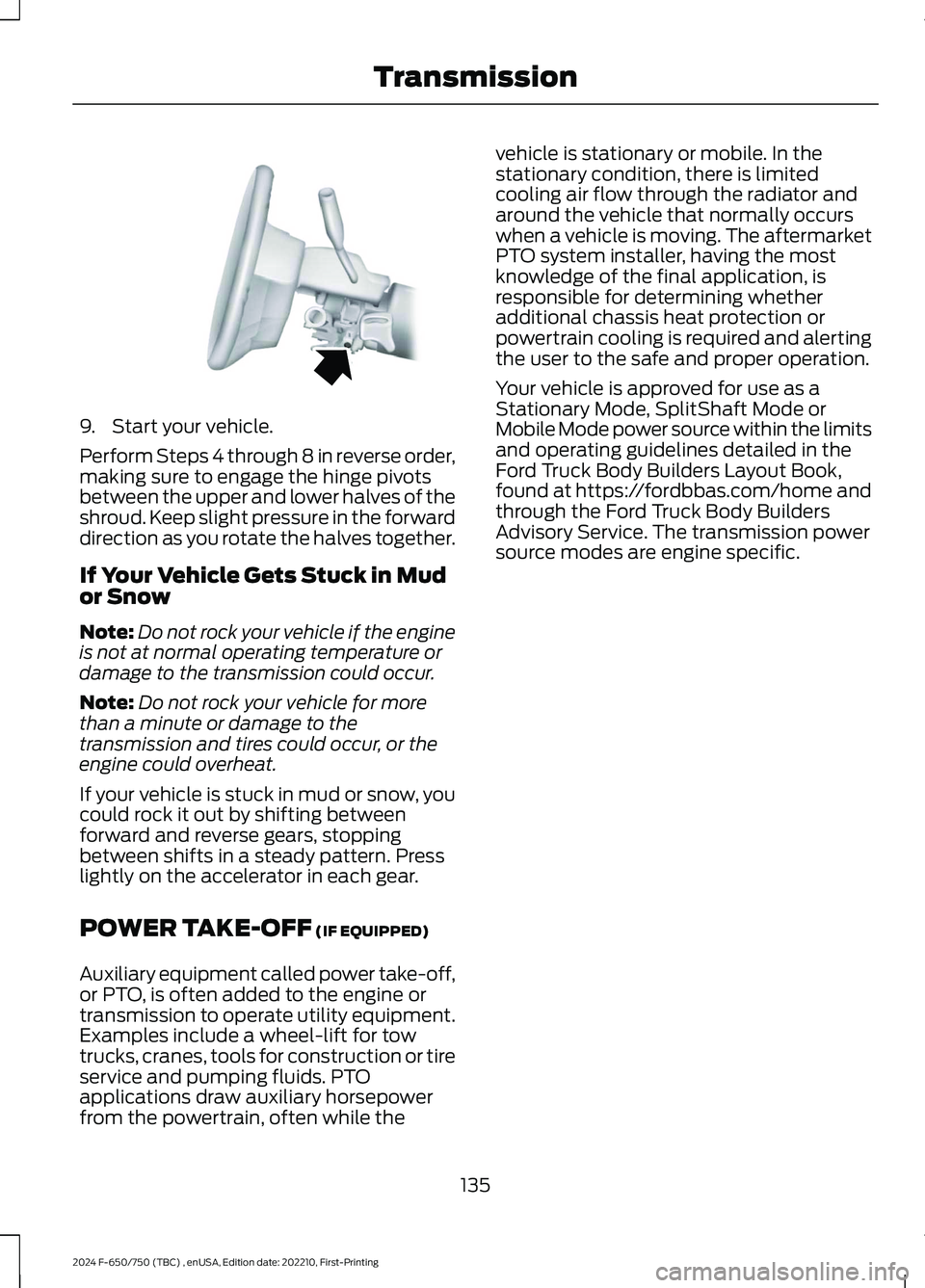
9.Start your vehicle.
Perform Steps 4 through 8 in reverse order,making sure to engage the hinge pivotsbetween the upper and lower halves of theshroud. Keep slight pressure in the forwarddirection as you rotate the halves together.
If Your Vehicle Gets Stuck in Mudor Snow
Note:Do not rock your vehicle if the engineis not at normal operating temperature ordamage to the transmission could occur.
Note:Do not rock your vehicle for morethan a minute or damage to thetransmission and tires could occur, or theengine could overheat.
If your vehicle is stuck in mud or snow, youcould rock it out by shifting betweenforward and reverse gears, stoppingbetween shifts in a steady pattern. Presslightly on the accelerator in each gear.
POWER TAKE-OFF (IF EQUIPPED)
Auxiliary equipment called power take-off,or PTO, is often added to the engine ortransmission to operate utility equipment.Examples include a wheel-lift for towtrucks, cranes, tools for construction or tireservice and pumping fluids. PTOapplications draw auxiliary horsepowerfrom the powertrain, often while the
vehicle is stationary or mobile. In thestationary condition, there is limitedcooling air flow through the radiator andaround the vehicle that normally occurswhen a vehicle is moving. The aftermarketPTO system installer, having the mostknowledge of the final application, isresponsible for determining whetheradditional chassis heat protection orpowertrain cooling is required and alertingthe user to the safe and proper operation.
Your vehicle is approved for use as aStationary Mode, SplitShaft Mode orMobile Mode power source within the limitsand operating guidelines detailed in theFord Truck Body Builders Layout Book,found at https://fordbbas.com/home andthrough the Ford Truck Body BuildersAdvisory Service. The transmission powersource modes are engine specific.
135
2024 F-650/750 (TBC) , enUSA, Edition date: 202210, First-PrintingTransmissionE163186
Page 140 of 386
GENERAL INFORMATION
WARNING: Exceeding these ratingsby overloading can cause componentfailure resulting in property damage,personal injury or death.
Fluid Temperature
If the operating temperature exceeds250°F (121°C), the rate of axle lubricationoxidation increases and shortens the lifeof the lubricant and seals, requiring axlelubrication changes to become morefrequent to preserve the axle. Do notconsistently run extreme pressure (EP)lubricants above 250°F (121°C).
Axle Conversions
WARNING: When operating aloaded vehicle, the driver must keep alladjustable axles on the ground at alltimes, supporting their share of thevehicle’s load. Failure to do so canoverload other axles, tires, wheels,springs, steering components, brakesand frames, resulting in early componentfailure, loss of vehicle control, possibleproperty damage and personal injury.
We do not recommend, or approve,performing axle conversions. However, weunderstand that, on occasion, others installaftermarket add-on axles on the truckchassis that allow operator control forweight transfer from other axles (such asair lift axles).
2-SPEED REAR AXLE (IF EQUIPPED)
WARNING: Never shift atwo-speed axle when descending asteep grade as this may cause loss ofvehicle control and result in personalinjury.
Note:Do not shift between ranges whenthe speed control is on.
A two-speed rear axle allows the driver toselect a low range for greater pulling powerand a high range for greater road speedand fuel economy. You can also use theseranges to provide extra steps betweentransmission shifts when driving on steepgrades or fuel economy may be factors.
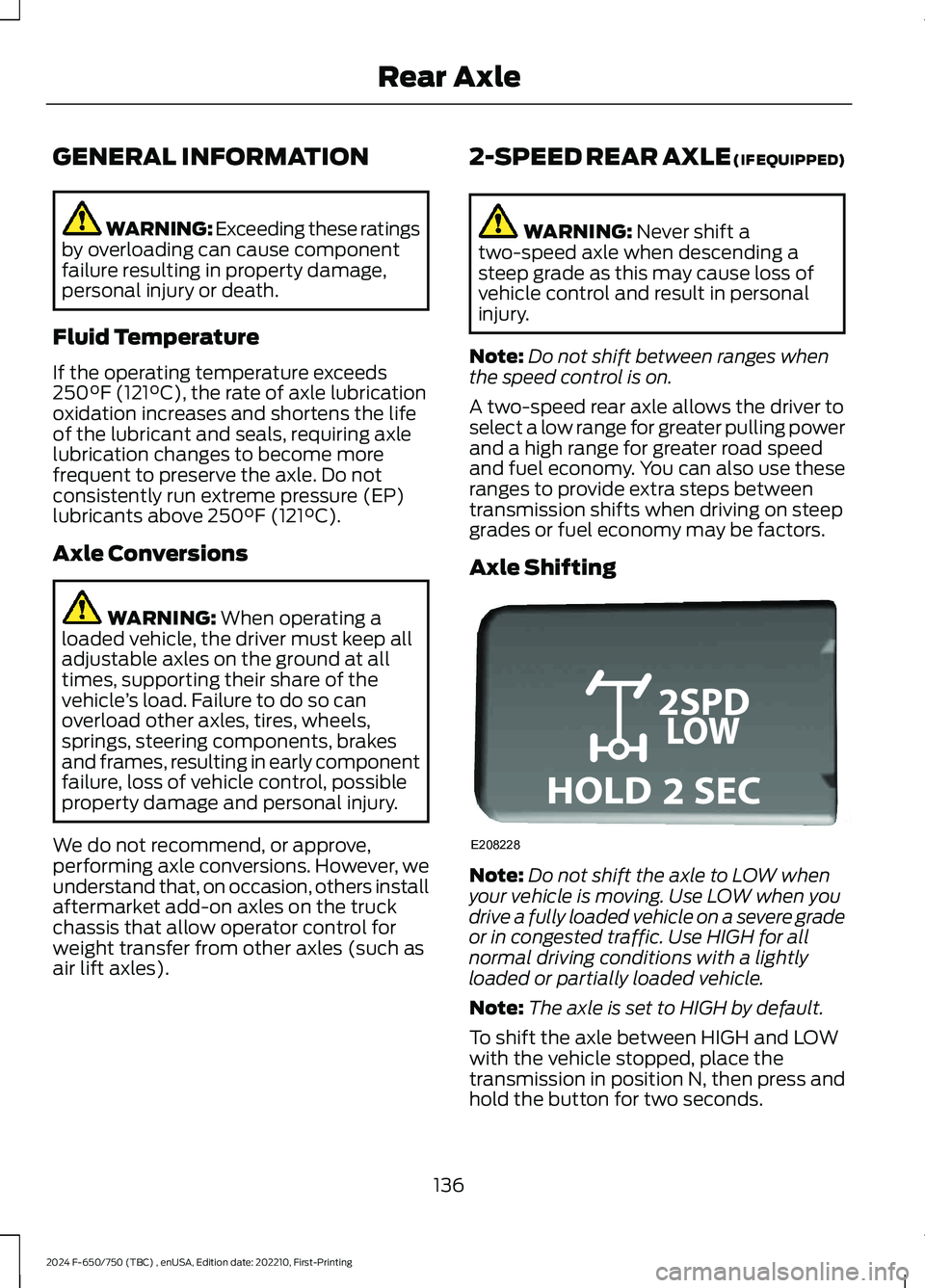
Axle Shifting
Note:Do not shift the axle to LOW whenyour vehicle is moving. Use LOW when youdrive a fully loaded vehicle on a severe gradeor in congested traffic. Use HIGH for allnormal driving conditions with a lightlyloaded or partially loaded vehicle.
Note:The axle is set to HIGH by default.
To shift the axle between HIGH and LOWwith the vehicle stopped, place thetransmission in position N, then press andhold the button for two seconds.
136
2024 F-650/750 (TBC) , enUSA, Edition date: 202210, First-PrintingRear AxleE208228
Page 157 of 386
PRINCIPLE OF OPERATION -
VEHICLES WITH: HYDRAULIC
BRAKES
WARNING: Vehicle modificationsinvolving braking system, aftermarketroof racks, suspension, steering system,tire construction and wheel and tire sizemay change the handling characteristicsof your vehicle and may adversely affectthe performance of the electronicstability control system. In addition,installing any stereo loudspeakers mayinterfere with and adversely affect theelectronic stability control system. Installany aftermarket stereo loudspeaker asfar as possible from the front centerconsole, the tunnel, and the front seatsin order to minimize the risk of interferingwith the electronic stability controlsensors. Reducing the effectiveness ofthe electronic stability control systemcould lead to an increased risk of loss ofvehicle control, vehicle rollover, personalinjury and death.
WARNING: Remember that evenadvanced technology cannot defy thelaws of physics. It's always possible tolose control of a vehicle due toinappropriate driver input for theconditions. Aggressive driving on anyroad condition can cause you to losecontrol of your vehicle increasing the riskof personal injury or property damage.Activation of the electronic stabilitycontrol system is an indication that atleast some of the tires have exceededtheir ability to grip the road; this could
reduce the operator's ability to controlthe vehicle potentially resulting in a lossof vehicle control, vehicle rollover,personal injury and death. If yourelectronic stability control systemactivates, SLOW DOWN.
The system turns on each time you switchthe ignition on.
If a fault occurs in either the stabilitycontrol or the traction control system, thefollowing conditions are possible:
•The stability and traction control lightilluminate.
•The stability control and tractioncontrol systems are not maintainingtraction of the wheels.
If a driving condition activates either thestability control or the traction controlsystem, the following conditions arepossible:
•The stability and traction control lightflash.
•Your vehicle slows down.
•The system reduces engine power.
•A vibration in the brake pedal.
•The brake pedal is stiffer than usual.
•If the driving condition is severe andyour foot is not on the brake, the brakepedal could move as the systemapplies higher brake force.
The stability control system has severalfeatures built into it to help you maintaincontrol of your vehicle:
Electronic Stability Control
The system assists in preventing skids orlateral slides by applying the brakes to oneor more of the wheels individually and, ifnecessary, decreases engine power.
153
2024 F-650/750 (TBC) , enUSA, Edition date: 202210, First-PrintingStability Control
Page 158 of 386
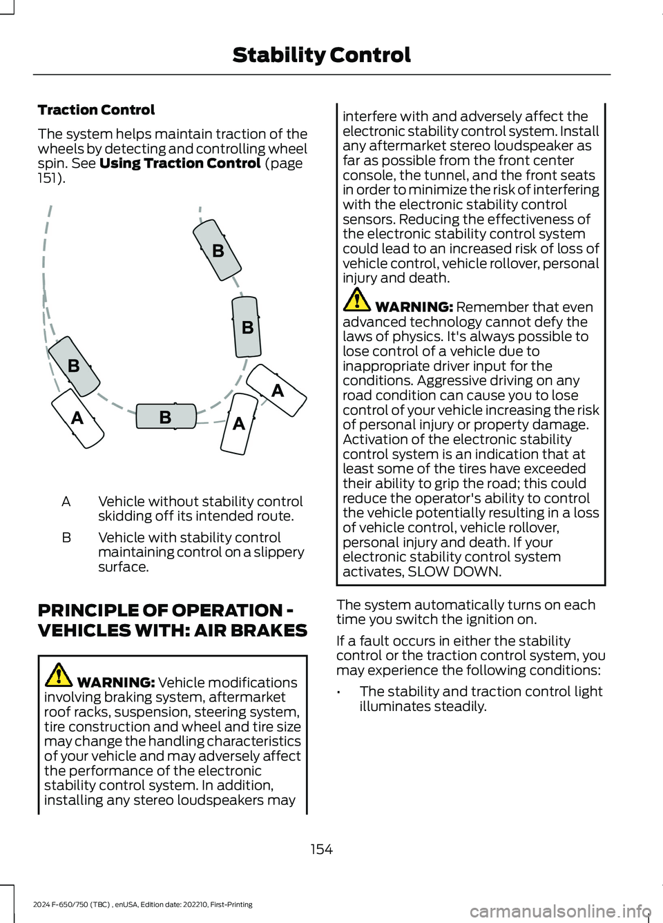
Traction Control
The system helps maintain traction of thewheels by detecting and controlling wheelspin. See Using Traction Control (page151).
Vehicle without stability controlskidding off its intended route.A
Vehicle with stability controlmaintaining control on a slipperysurface.
B
PRINCIPLE OF OPERATION -
VEHICLES WITH: AIR BRAKES
WARNING: Vehicle modificationsinvolving braking system, aftermarketroof racks, suspension, steering system,tire construction and wheel and tire sizemay change the handling characteristicsof your vehicle and may adversely affectthe performance of the electronicstability control system. In addition,installing any stereo loudspeakers may
interfere with and adversely affect theelectronic stability control system. Installany aftermarket stereo loudspeaker asfar as possible from the front centerconsole, the tunnel, and the front seatsin order to minimize the risk of interferingwith the electronic stability controlsensors. Reducing the effectiveness ofthe electronic stability control systemcould lead to an increased risk of loss ofvehicle control, vehicle rollover, personalinjury and death.
WARNING: Remember that evenadvanced technology cannot defy thelaws of physics. It's always possible tolose control of a vehicle due toinappropriate driver input for theconditions. Aggressive driving on anyroad condition can cause you to losecontrol of your vehicle increasing the riskof personal injury or property damage.Activation of the electronic stabilitycontrol system is an indication that atleast some of the tires have exceededtheir ability to grip the road; this couldreduce the operator's ability to controlthe vehicle potentially resulting in a lossof vehicle control, vehicle rollover,personal injury and death. If yourelectronic stability control systemactivates, SLOW DOWN.
The system automatically turns on eachtime you switch the ignition on.
If a fault occurs in either the stabilitycontrol or the traction control system, youmay experience the following conditions:
•The stability and traction control lightilluminates steadily.
154
2024 F-650/750 (TBC) , enUSA, Edition date: 202210, First-PrintingStability ControlE72903
Page 166 of 386
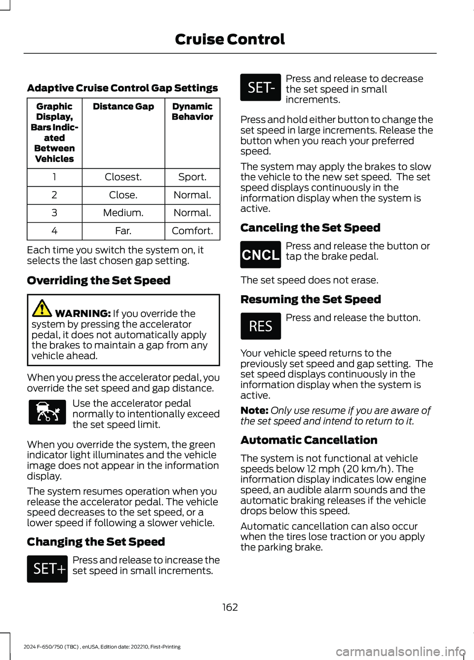
Adaptive Cruise Control Gap Settings
DynamicBehaviorDistance GapGraphicDisplay,Bars Indic-atedBetweenVehicles
Sport.Closest.1
Normal.Close.2
Normal.Medium.3
Comfort.Far.4
Each time you switch the system on, itselects the last chosen gap setting.
Overriding the Set Speed
WARNING: If you override thesystem by pressing the acceleratorpedal, it does not automatically applythe brakes to maintain a gap from anyvehicle ahead.
When you press the accelerator pedal, youoverride the set speed and gap distance.
Use the accelerator pedalnormally to intentionally exceedthe set speed limit.
When you override the system, the greenindicator light illuminates and the vehicleimage does not appear in the informationdisplay.
The system resumes operation when yourelease the accelerator pedal. The vehiclespeed decreases to the set speed, or alower speed if following a slower vehicle.
Changing the Set Speed
Press and release to increase theset speed in small increments.
Press and release to decreasethe set speed in smallincrements.
Press and hold either button to change theset speed in large increments. Release thebutton when you reach your preferredspeed.
The system may apply the brakes to slowthe vehicle to the new set speed. The setspeed displays continuously in theinformation display when the system isactive.
Canceling the Set Speed
Press and release the button ortap the brake pedal.
The set speed does not erase.
Resuming the Set Speed
Press and release the button.
Your vehicle speed returns to thepreviously set speed and gap setting. Theset speed displays continuously in theinformation display when the system isactive.
Note:Only use resume if you are aware ofthe set speed and intend to return to it.
Automatic Cancellation
The system is not functional at vehiclespeeds below 12 mph (20 km/h). Theinformation display indicates low enginespeed, an audible alarm sounds and theautomatic braking releases if the vehicledrops below this speed.
Automatic cancellation can also occurwhen the tires lose traction or you applythe parking brake.
162
2024 F-650/750 (TBC) , enUSA, Edition date: 202210, First-PrintingCruise ControlE144529 E246884 E246885 E265298
Page 182 of 386
LOAD LIMIT
WARNING: Do not exceedthe GVWR or the GAWRspecified on the SafetyCompliance Certification Label.
WARNING: Do not usereplacement tires with lowerload carrying capacities than theoriginal tires because they maylower the vehicle's GVWR andGAWR limitations. Replacementtires with a higher limit than theoriginals do not increase theGVWR and GAWR limitations.
WARNING: Exceeding anyvehicle weight rating limitationcould result in serious damageto the vehicle and/or personalinjury.
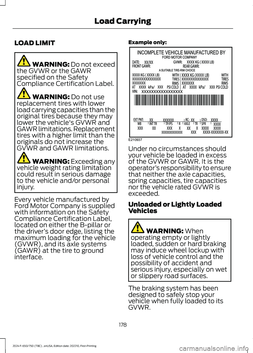
Every vehicle manufactured byFord Motor Company is suppliedwith information on the SafetyCompliance Certification Label,located on either the B-pillar orthe driver’s door edge, listing themaximum loading for the vehicle(GVWR), and its axle systems(GAWR) at the tire to groundinterface.
Example only:
Under no circumstances shouldyour vehicle be loaded in excessof the GVWR or GAWR. It is theoperator’s responsibility to ensurethat neither the axle capacities,spring capacities, tire capacitiesnor the vehicle rated GVWR isexceeded.
Unloaded or Lightly LoadedVehicles
WARNING: Whenoperating empty or lightlyloaded, sudden or hard brakingmay induce wheel lockup withloss of vehicle control and thepossibility of accident andserious injury, especially on wetor slippery road surfaces.
The braking system has beendesigned to safely stop yourvehicle when fully loaded to itsGVWR.
178
2024 F-650/750 (TBC) , enUSA, Edition date: 202210, First-PrintingLoad CarryingE210937