2024 FORD F650/750 battery
[x] Cancel search: batteryPage 109 of 386

ENGINE IDLE SHUTDOWN (IF
EQUIPPED)
WARNING: In the event of engineshutdown, make sure your vehicle issafely off the road and the problem isresolved before returning to the road.Failure to do so may result in a crash,serious injury or death.
This feature automatically shuts down theengine when it has been idling in park (P)or neutral (N) for an extended period,depending on the setting.
When the engine idle shutdown processhas started:
•A chime sounds and a messageappears in the information displayshowing a timer counting down from30 seconds.
•You can reset the timer by pressing thebrake pedal, accelerator pedal, or byshifting into another gear.
•If you do not intervene within 30seconds, the engine shuts down and amessage appears in the informationdisplay alerting you that the engine hasshut down.
•Shortly after the engine has shut down,the electrical system simulates a keyoff and even though the ignition is stillon, the electrical system simulates anormal accessory delay period beforeshutting down.
•You must switch the ignition off toreset the system before restarting yourvehicle.
The engine idle shutdown timer does notstart if:
•The engine is operating in batterycharge protect or power take-off mode.
•The exhaust emission control device isregenerating.
ENGINE BLOCK HEATER (IF
EQUIPPED)
WARNING: Failure to follow engineblock heater instructions could result inproperty damage or serious personalinjury.
WARNING: Do not use your heaterwith ungrounded electrical systems ortwo-pronged adapters. There is a risk ofelectrical shock.
WARNING: Do not fully close thehood, or allow it to drop under its ownweight when using the engine blockheater. This could damage the powercable and may cause an electrical shortresulting in fire, injury and propertydamage.
Note:The heater is most effective whenoutdoor temperatures are below 0°F(-18°C).
The heater acts as a starting aid bywarming the engine coolant. This allowsthe climate control system to respondquickly. The equipment includes a heaterelement (installed in the engine block) anda wire harness. You can connect thesystem to a grounded 120-volt ACelectrical source.
105
2024 F-650/750 (TBC) , enUSA, Edition date: 202210, First-PrintingStarting and Stopping the Engine
Page 124 of 386

Your vehicle may not pass the I/M test ifthe service engine soon indicator is on ornot working properly (bulb is burned out),or if the OBD-II system has determinedthat some of the emission control systemshave not been properly checked. In thiscase, the vehicle is not ready for I/Mtesting.
If the vehicle’s engine or transmission hasjust been serviced, or the battery hasrecently run down or been replaced, theOBD-II system may indicate that thevehicle is not ready for I/M testing. Todetermine if the vehicle is ready for I/Mtesting, turn the ignition key to the onposition for 15 seconds without crankingthe engine. If the service engine soonindicator blinks eight times, it means thatthe vehicle is not ready for I/M testing; ifthe service engine soon indicator stays onsolid, it means that your vehicle is readyfor I/M testing.
The OBD-II system checks the emissioncontrol system during normal driving. Acomplete check may take several days.
If the vehicle is not ready for I/M testing,you can perform the following driving cycleconsisting of mixed city and highwaydriving:
1.15 minutes of steady driving on anexpressway or highway followed by 20minutes of stop-and-go driving with atleast four 30-second idle periods.
2.Allow your vehicle to sit for at leasteight hours with the ignition off. Then,start the vehicle and complete theabove driving cycle. The vehicle mustwarm up to its normal operatingtemperature. Once started, do not turnoff the vehicle until the above drivingcycle is complete.
If the vehicle is still not ready for I/Mtesting, you need to repeat the abovedriving cycle.
SELECTIVE CATALYTIC
REDUCTANT SYSTEM - DIESEL
Your vehicle may have a selective catalyticreduction system. This system helpsreduce emission levels of oxides ofnitrogen from the exhaust system. Thesystem automatically injects dieselexhaust fluid into the exhaust system toenable correct selective catalytic reductionsystem function.
Note:Selective catalytic reduction systemsare not fitted to vehicles in markets whereonly high-sulfur diesel fuel is available.
Diesel Exhaust Fluid Level
In order for the system to operate correctlyyou must maintain the diesel exhaust fluidlevel.
The system has a sensor to monitor fluidlevel and quality/concentration. A warningmessage appears in the informationdisplay when the diesel exhaust fluid levelis low. If a warning message appears, refillthe diesel exhaust fluid tank as soon aspossible. See Information Messages(page 75).
Filling the Diesel Exhaust FluidTank
WARNING: Keep diesel exhaustfluid out of reach of children. Avoidcontact with skin, eyes or clothing. Incase of contact with your eyes, flushimmediately with water and get promptmedical attention. In case of contactwith your skin, clean immediately withsoap and water. If you swallow anydiesel exhaust fluid, drink plenty ofwater, call a physician immediately.
120
2024 F-650/750 (TBC) , enUSA, Edition date: 202210, First-PrintingEngine Emission Control
Page 194 of 386

HAZARD FLASHERS
Note:If used when the vehicle is notrunning, the battery loses charge. As a result,there may be insufficient power to restartyour vehicle.
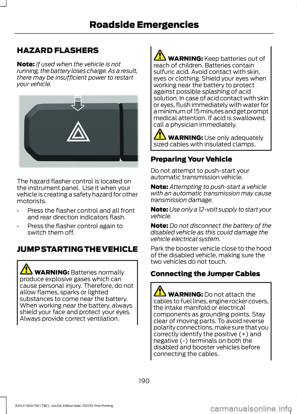
The hazard flasher control is located onthe instrument panel. Use it when yourvehicle is creating a safety hazard for othermotorists.
•Press the flasher control and all frontand rear direction indicators flash.
•Press the flasher control again toswitch them off.
JUMP STARTING THE VEHICLE
WARNING: Batteries normallyproduce explosive gases which cancause personal injury. Therefore, do notallow flames, sparks or lightedsubstances to come near the battery.When working near the battery, alwaysshield your face and protect your eyes.Always provide correct ventilation.
WARNING: Keep batteries out ofreach of children. Batteries containsulfuric acid. Avoid contact with skin,eyes or clothing. Shield your eyes whenworking near the battery to protectagainst possible splashing of acidsolution. In case of acid contact with skinor eyes, flush immediately with water fora minimum of 15 minutes and get promptmedical attention. If acid is swallowed,call a physician immediately.
WARNING: Use only adequatelysized cables with insulated clamps.
Preparing Your Vehicle
Do not attempt to push-start yourautomatic transmission vehicle.
Note:Attempting to push-start a vehiclewith an automatic transmission may causetransmission damage.
Note:Use only a 12-volt supply to start yourvehicle.
Note:Do not disconnect the battery of thedisabled vehicle as this could damage thevehicle electrical system.
Park the booster vehicle close to the hoodof the disabled vehicle, making sure thetwo vehicles do not touch.
Connecting the Jumper Cables
WARNING: Do not attach thecables to fuel lines, engine rocker covers,the intake manifold or electricalcomponents as grounding points. Stayclear of moving parts. To avoid reversepolarity connections, make sure that youcorrectly identify the positive (+) andnegative (-) terminals on both thedisabled and booster vehicles beforeconnecting the cables.
190
2024 F-650/750 (TBC) , enUSA, Edition date: 202210, First-PrintingRoadside EmergenciesE304635
Page 195 of 386

WARNING: Do not attach the endof the positive cable to the studs orL-shaped eyelet located above thepositive (+) terminal of your vehicle’sbattery. High current may flow throughand cause damage to the fuses.
WARNING: Do not connect the endof the second cable to the negative (-)terminal of the battery to be jumped. Aspark may cause an explosion of thegases that surround the battery.
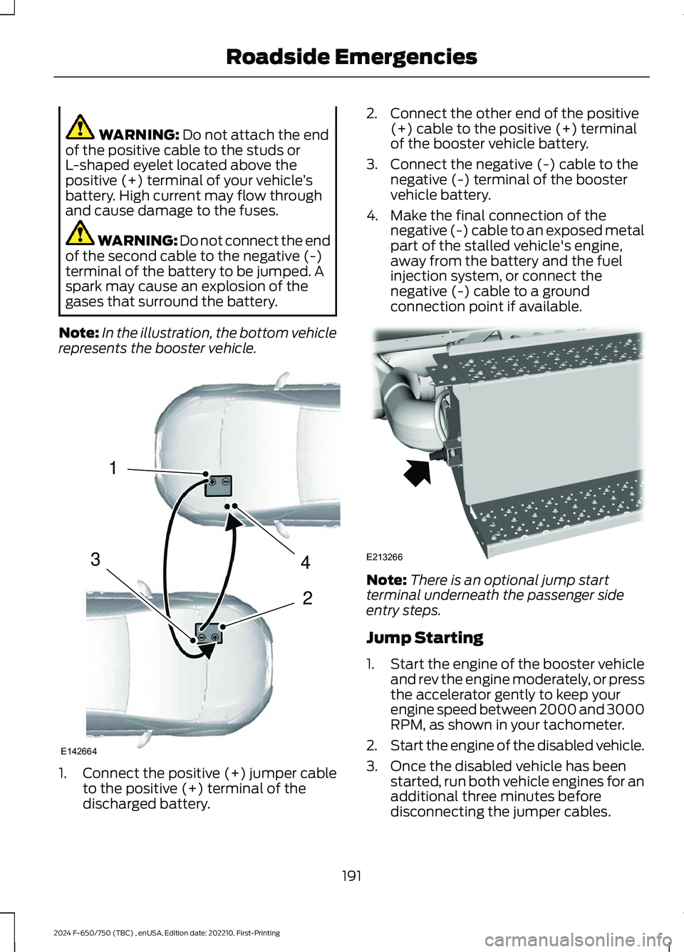
Note:In the illustration, the bottom vehiclerepresents the booster vehicle.
1.Connect the positive (+) jumper cableto the positive (+) terminal of thedischarged battery.
2.Connect the other end of the positive(+) cable to the positive (+) terminalof the booster vehicle battery.
3.Connect the negative (-) cable to thenegative (-) terminal of the boostervehicle battery.
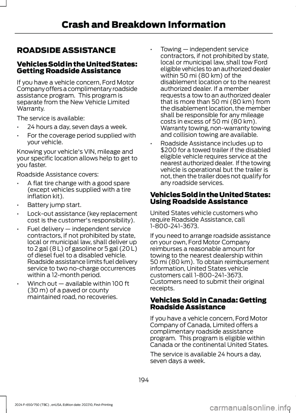
4.Make the final connection of thenegative (-) cable to an exposed metalpart of the stalled vehicle's engine,away from the battery and the fuelinjection system, or connect thenegative (-) cable to a groundconnection point if available.
Note:There is an optional jump startterminal underneath the passenger sideentry steps.
Jump Starting
1.Start the engine of the booster vehicleand rev the engine moderately, or pressthe accelerator gently to keep yourengine speed between 2000 and 3000RPM, as shown in your tachometer.
2.Start the engine of the disabled vehicle.
3.Once the disabled vehicle has beenstarted, run both vehicle engines for anadditional three minutes beforedisconnecting the jumper cables.
191
2024 F-650/750 (TBC) , enUSA, Edition date: 202210, First-PrintingRoadside Emergencies4213E142664 E213266
Page 196 of 386

Removing the Jumper Cables
Remove the jumper cables in the reverseorder that they were connected.
1.Remove the negative (-) jumper cablefrom the disabled vehicle.
2.Remove the jumper cable on thenegative (-) terminal of the boostervehicle battery.
3.Remove the jumper cable from thepositive (+) terminal of the boostervehicle battery.
4.Remove the jumper cable from thepositive (+) terminal of the disabledvehicle battery.
5.Allow the engine to idle for at least oneminute.
TRANSPORTING THE VEHICLE
WARNING: Block the wheels tohelp prevent the vehicle from moving.
WARNING: Unexpected andpossibly sudden vehicle movement mayoccur if you do not take theseprecautions.
If you need to have your vehicle towed,contact a professional towing service or,if you are a member of a roadsideassistance program, your roadsideassistance service provider.
192
2024 F-650/750 (TBC) , enUSA, Edition date: 202210, First-PrintingRoadside Emergencies4132E142665 E143886
Page 198 of 386

ROADSIDE ASSISTANCE
Vehicles Sold in the United States:Getting Roadside Assistance
If you have a vehicle concern, Ford MotorCompany offers a complimentary roadsideassistance program. This program isseparate from the New Vehicle LimitedWarranty.
The service is available:
•24 hours a day, seven days a week.
•For the coverage period supplied withyour vehicle.
Knowing your vehicle's VIN, mileage andyour specific location allows help to get toyou faster.
Roadside Assistance covers:
•A flat tire change with a good spare(except vehicles supplied with a tireinflation kit).
•Battery jump start.
•Lock-out assistance (key replacementcost is the customer's responsibility).
•Fuel delivery — independent servicecontractors, if not prohibited by state,local or municipal law, shall deliver upto 2 gal (8 L) of gasoline or 5 gal (20 L)of diesel fuel to a disabled vehicle.Roadside assistance limits fuel deliveryservice to two no-charge occurrenceswithin a 12-month period.
•Winch out — available within 100 ft(30 m) of a paved or countymaintained road, no recoveries.
•Towing — independent servicecontractors, if not prohibited by state,local or municipal law, shall tow Fordeligible vehicles to an authorized dealerwithin 50 mi (80 km) of thedisablement location or to the nearestauthorized dealer. If a memberrequests a tow to an authorized dealerthat is more than 50 mi (80 km) fromthe disablement location, the membershall be responsible for any mileagecosts in excess of 50 mi (80 km).Warranty towing, non-warranty towingand collision towing are available.
•Roadside Assistance includes up to$200 for a towed trailer if the disabledeligible vehicle requires service at thenearest authorized dealer. If the towingvehicle is operational but the trailer isnot, then the trailer does not qualify forany roadside services.
Vehicles Sold in the United States:Using Roadside Assistance
United States vehicle customers whorequire Roadside Assistance, call1-800-241-3673.
If you need to arrange roadside assistanceon your own, Ford Motor Companyreimburses a reasonable amount fortowing to the nearest dealership within50 mi (80 km). To obtain reimbursementinformation, United States vehiclecustomers call 1-800-241-3673.Customers need to submit their originalreceipts.
Vehicles Sold in Canada: GettingRoadside Assistance
If you have a vehicle concern, Ford MotorCompany of Canada, Limited offers acomplimentary roadside assistanceprogram. This program is eligible withinCanada or the continental United States.
The service is available 24 hours a day,seven days a week.
194
2024 F-650/750 (TBC) , enUSA, Edition date: 202210, First-PrintingCrash and Breakdown Information
Page 206 of 386

FUSE SPECIFICATION CHART
Engine Compartment Fuse Box
WARNING: Always disconnect thebattery before servicing high currentfuses.
WARNING: To reduce risk ofelectrical shock, always replace thecover to the power distribution boxbefore reconnecting the battery orrefilling fluid reservoirs.
The engine compartment fuse box is in theengine compartment. It has high-currentfuses that protect your vehicle's mainelectrical systems from overloads.
If you disconnect and reconnect thebattery, you need to reset some features.See Changing the 12V Battery (page 246).
Replace fuses with the same type andrating. See Changing a Fuse (page 211).
Protected ComponentRatingItem
Horn.20 A1
Blower motor.40 A2
202
2024 F-650/750 (TBC) , enUSA, Edition date: 202210, First-PrintingFusesE251921
Page 208 of 386

Protected ComponentRatingItem
Not used.—26
Upfitter battery feed.20 A27
Not used.—28
Glow plug relay coil.10 A29
Not used.—30
Hydromax pump.60 A31
Powertrain control module.20 A32
Heater exhaust gas oxygensensor 11 (gas).20 A33
Heater exhaust gas oxygensensor 12 (gas).Heater exhaust gas oxygensensor 21 (gas).Canister vent solenoid (gas).Canister purge solenoid(gas).Variable camshaft timingactuator 11 (gas).Exhaust gas recirculationcooling bypass valve(diesel).
A/C clutch relay (diesel).10 A34Variable oil pump (diesel).Cooling fan (diesel).Fan clutch (gas).Exhaust brake switch(diesel).Variable oil pressure control(gas).Customer access vehiclepower 3 feed.
Coil on plug (gas).20 A35Nitrogen oxide sensorcontrol module feedgas(diesel).Nitrogen oxide sensorcontrol module midbed(diesel).
204
2024 F-650/750 (TBC) , enUSA, Edition date: 202210, First-PrintingFuses