2024 FORD F650/750 ABS
[x] Cancel search: ABSPage 197 of 386
We recommend the use of a wheel lift anddollies or flatbed equipment to tow yourvehicle. Do not tow with a slingbelt. FordMotor Company has not approved aslingbelt towing procedure. Vehicledamage may occur if towed incorrectly, orby any other means.
Ford Motor Company produces a towingmanual for all authorized tow truckoperators. Have your tow truck operatorrefer to this manual for proper hook-upand towing procedures for your vehicle.
It is acceptable to have your two-wheeldrive vehicle towed with the front wheelson the ground (without dollies) and therear wheels off the ground.
TOWING POINTS (IF EQUIPPED)
WARNING: Using recovery hooksis dangerous and should only be done bya person familiar with proper vehiclerecovery safety practices. Improper useof recovery hooks may cause hook failureor separation from the vehicle and couldresult in serious injury or death.
WARNING: Always slowly removethe slack from the recovery strap priorto pulling. Failure to do so can introducesignificantly higher loads which cancause the recovery hooks to break off, orthe recovery strap to fail which can causeserious injury or death.
WARNING: Never link two strapstogether with a clevis pin. These heavymetal objects could become projectilesif the strap breaks and can cause seriousinjury or death.
Your vehicle comes equipped withframe-mounted front recovery hooks.These hooks should never have a loadapplied to them greater than the grossvehicle weight rating of your vehicle.
Before using recovery hooks:
•Make sure all attaching points aresecure and capable of withstandingthe applied load.
•Never use chains, cables or tow strapswith metal hook ends.
•Only use recovery straps that have aminimum breaking strength two tothree times the gross vehicle weight ofthe stuck vehicle.
•Make sure the recovery strap is in goodcondition and free of visible cuts, tearsor damage.
•Use a damper device such as a tarp,heavy blanket or piece of carpetdraped over the recovery strap to helpabsorb the energy in the event thestrap breaks.
•Make sure the stuck vehicle is notloaded heavier than its gross vehicleweight rating specified on thecertification label.
•Always align the tow vehicle and stuckvehicle in a straight line (within 10degrees).
•Keep bystanders to the sides of thevehicle, at a distance of at least twicethe length of the recovery strap. Thishelps avoid injury from the hazard of arecovery hook or strap breaking, or avehicle lurching into their path.
193
2024 F-650/750 (TBC) , enUSA, Edition date: 202210, First-PrintingRoadside Emergencies
Page 220 of 386
Front of vehicle
Verify running lights are clean and unbroken.
Inspect for any missing or loose fasteners, power steeringfluid leaks and damage to power steering hoses.Steering gear
Verify connecting links, arms and rods are not worn or cracked.Steering linkage
Verify joints, sockets and boot seals are not worn or loose.
Verify cotter keys, nuts and bolts are not loose or missing.
Inspect front and rear tow hooks for damage or loosemounting. This is particularly important on vehicles that usethem frequently.
Tow hooks
Front suspension
Inspect for missing, broken or shifted leaves, or leaves thatmay be in contact with (or nearly contacting) a tire, rim, brakedrum, frame or body component.
Springs
Note: Never apply grease to spring pads.
Make sure there the following items are properly tightenedand that there are no cracks, breaks, wear, damage to springhangers, bolts, bushings, axle mounting bolts, and nuts.
Spring mounts
Inspect for any cracks, leaks, or missing or broken bolts orbushings.Shock absorbers
216
2024 F-650/750 (TBC) , enUSA, Edition date: 202210, First-PrintingVehicle Inspection Guide
Page 223 of 386
Tractor-coupling system
Inspect for loose or missing mounting brackets, clamps, boltsor nuts. Verify solid attachment of both fifth wheel and theslide mounting.
Mounting bolts
Inspect for cracks or breaks in the platform structure.Platform
Verify engagement of the safety latch.Safety latch
Verify the safety latch is in the engaged position, and thatany safety latch is in place.Release arm
Verify the kingpin is not bent or worn, the apron lies flat onthe fifth-wheel skid plate and that the visible part of the apronis not bent, worn, cracked or broken.
Kingpin and apron
Rear suspension
Inspect for missing, broken or shifted leaves, or leaves thatmay be in contact with (or nearly contacting) a tire, rim, brakedrum, frame or body component.
Springs (if equipped)
Inspect for any cracked or broken spring hangers; brokenmissing or loose bolts; missing or damaged bushings; broken,loose or missing axle mounting parts.
Spring mounts (ifequipped)
Verify torsion arm is not cracked, broken or missing.Torsion arm and shockabsorbersInspect the shock absorber for cracks or leaks. There shouldbe no missing or broken mounting bolts or worn bushings.
Inspect for missing, broken or leaking components.Air suspension (ifequipped)Inspect for any cracked, broken or loose bolts; missing ordamaged bushings; broken, loose or missing axle mountingparts.
219
2024 F-650/750 (TBC) , enUSA, Edition date: 202210, First-PrintingVehicle Inspection Guide
Page 232 of 386

Do not use supplemental engine oiladditives because they are unnecessaryand could lead to engine damage that thevehicle warranty may not cover.
1.Clean the area surrounding the engineoil filler cap before you remove it.
2.Remove the engine oil filler cap.
3.Add engine oil that meets ourspecifications. See Capacities andSpecifications (page 291).
4.Reinstall the engine oil filler cap. Turnit clockwise until you feel a strongresistance.
Note: Do not add oil further than themaximum mark. Oil levels above themaximum mark may cause engine damage.
Note:Immediately soak up any oil spillagewith an absorbent cloth.
Engine Oil Pressure Warning Lamp
WARNING: If it illuminates whenyou are driving do not continue yourjourney, even if the oil level is correct.Have your vehicle checked.
It illuminates when you switchthe ignition on.
If it illuminates when the engineis running this indicates a malfunction.Stop your vehicle as soon as it is safe todo so and switch the engine off. Check theengine oil level. If the oil level is sufficient,this indicates a system malfunction. Haveyour vehicle checked as soon as possible.
CHANGING THE ENGINE OIL
AND OIL FILTER
WARNING: Do not add engine oilwhen the engine is hot. Failure to followthis instruction could result in personalinjury.
Your vehicle has an Intelligent Oil LifeMonitor™ that calculates the proper oilchange service interval. When theinformation display indicates: OIL CHANGEREQUIRED, change the engine oil and oilfilter. See Information Displays (page71).
The engine oil filter protects your engineby filtering harmful, abrasive or sludgeparticles and particles significantly smallerthan most available will-fit filters. SeeMotorcraft Parts (page 293).
1.Unscrew the oil filter and oil pan drainplug and wait for the oil to drain.
2.Replace the filter.
3.Reinstall the oil pan drain plug.
4.Refill the engine with new oil. SeeEngine Oil Capacity andSpecification (page 299).
5.Reset the Intelligent Oil Life Monitor™.See Information Displays (page 71).
Engine Lubrication for SevereService Operation
The following conditions define severeoperation:
•Frequent or extended idling such asover 10 minutes per hour of normaldriving.
•Low-speed operation or stationary use.
•If the vehicle is operated in sustained,ambient temperatures below -9°F(-23°C) or above 100°F (38°C).
228
2024 F-650/750 (TBC) , enUSA, Edition date: 202210, First-PrintingMaintenanceE67022
Page 236 of 386
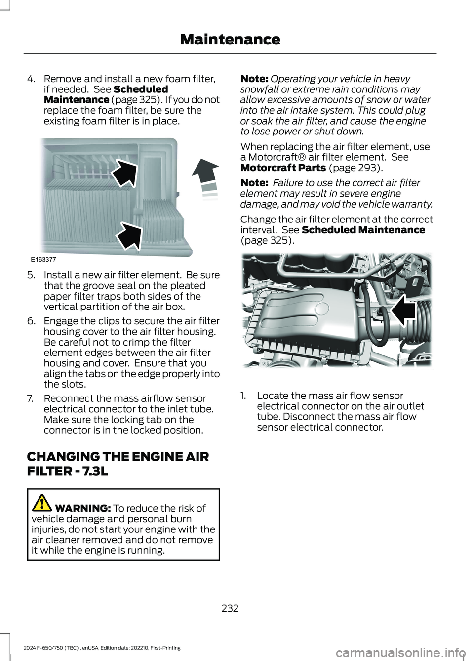
4.Remove and install a new foam filter,if needed. See ScheduledMaintenance (page 325). If you do notreplace the foam filter, be sure theexisting foam filter is in place.
5.Install a new air filter element. Be surethat the groove seal on the pleatedpaper filter traps both sides of thevertical partition of the air box.
6.Engage the clips to secure the air filterhousing cover to the air filter housing.Be careful not to crimp the filterelement edges between the air filterhousing and cover. Ensure that youalign the tabs on the edge properly intothe slots.
7.Reconnect the mass airflow sensorelectrical connector to the inlet tube.Make sure the locking tab on theconnector is in the locked position.
CHANGING THE ENGINE AIR
FILTER - 7.3L
WARNING: To reduce the risk ofvehicle damage and personal burninjuries, do not start your engine with theair cleaner removed and do not removeit while the engine is running.
Note:Operating your vehicle in heavysnowfall or extreme rain conditions mayallow excessive amounts of snow or waterinto the air intake system. This could plugor soak the air filter, and cause the engineto lose power or shut down.
When replacing the air filter element, usea Motorcraft® air filter element. SeeMotorcraft Parts (page 293).
Note: Failure to use the correct air filterelement may result in severe enginedamage, and may void the vehicle warranty.
Change the air filter element at the correctinterval. See Scheduled Maintenance(page 325).
1.Locate the mass air flow sensorelectrical connector on the air outlettube. Disconnect the mass air flowsensor electrical connector.
232
2024 F-650/750 (TBC) , enUSA, Edition date: 202210, First-PrintingMaintenanceE163377 E317615
Page 237 of 386
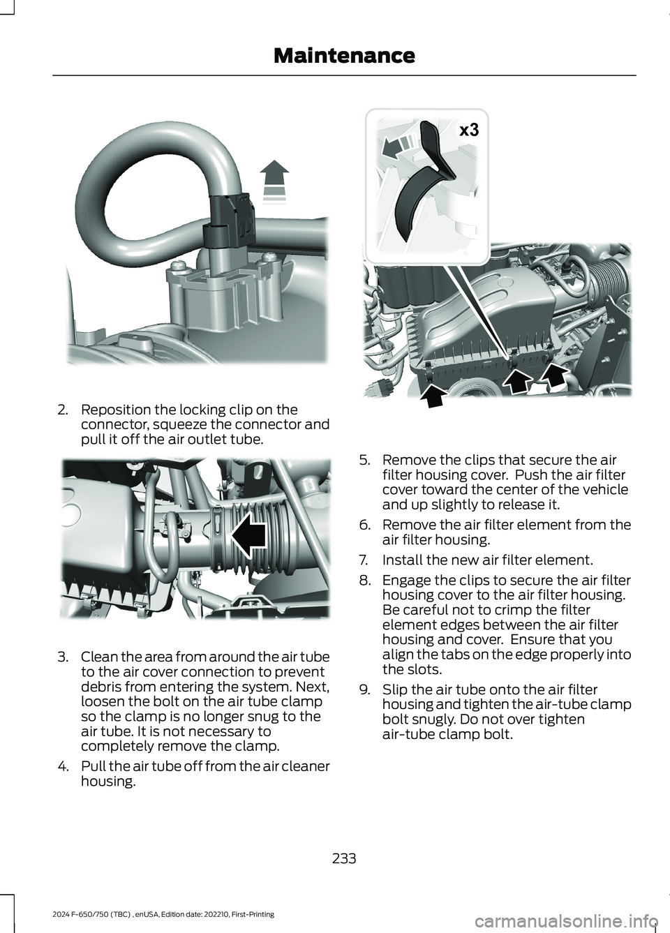
2.Reposition the locking clip on theconnector, squeeze the connector andpull it off the air outlet tube.
3.Clean the area from around the air tubeto the air cover connection to preventdebris from entering the system. Next,loosen the bolt on the air tube clampso the clamp is no longer snug to theair tube. It is not necessary tocompletely remove the clamp.
4.Pull the air tube off from the air cleanerhousing.
5.Remove the clips that secure the airfilter housing cover. Push the air filtercover toward the center of the vehicleand up slightly to release it.
6.Remove the air filter element from theair filter housing.
7.Install the new air filter element.
8.Engage the clips to secure the air filterhousing cover to the air filter housing.Be careful not to crimp the filterelement edges between the air filterhousing and cover. Ensure that youalign the tabs on the edge properly intothe slots.
9.Slip the air tube onto the air filterhousing and tighten the air-tube clampbolt snugly. Do not over tightenair-tube clamp bolt.
233
2024 F-650/750 (TBC) , enUSA, Edition date: 202210, First-PrintingMaintenanceE317616 E317617 x3E317618
Page 249 of 386
BRAKE FLUID CHECK
WARNING: Do not use any fluidother than the recommended brake fluidas this will reduce brake efficiency. Useof incorrect fluid could result in the lossof vehicle control, serious personal injuryor death.
WARNING: Only use brake fluidfrom a sealed container. Contaminationwith dirt, water, petroleum products orother materials may result in brakesystem damage or failure. Failure toadhere to this warning could result in theloss of vehicle control, serious personalinjury or death.
WARNING: Do not allow the fluidto touch your skin or eyes. If thishappens, rinse the affected areasimmediately with plenty of water andcontact your physician.
WARNING: The brake systemcould be affected if the brake fluid levelis below the MIN mark or above the MAXmark on the brake fluid reservoir.
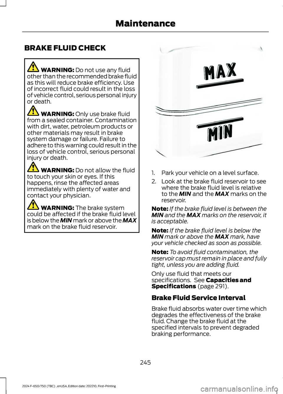
1.Park your vehicle on a level surface.
2.Look at the brake fluid reservoir to seewhere the brake fluid level is relativeto the MIN and the MAX marks on thereservoir.
Note:If the brake fluid level is between theMIN and the MAX marks on the reservoir, itis acceptable.
Note:If the brake fluid level is below theMIN mark or above the MAX mark, haveyour vehicle checked as soon as possible.
Note:To avoid fluid contamination, thereservoir cap must remain in place and fullytight, unless you are adding fluid.
Only use fluid that meets ourspecifications. See Capacities andSpecifications (page 291).
Brake Fluid Service Interval
Brake fluid absorbs water over time whichdegrades the effectiveness of the brakefluid. Change the brake fluid at thespecified intervals to prevent degradedbraking performance.
245
2024 F-650/750 (TBC) , enUSA, Edition date: 202210, First-PrintingMaintenanceE170684
Page 257 of 386
4.Disconnect the electrical connector.
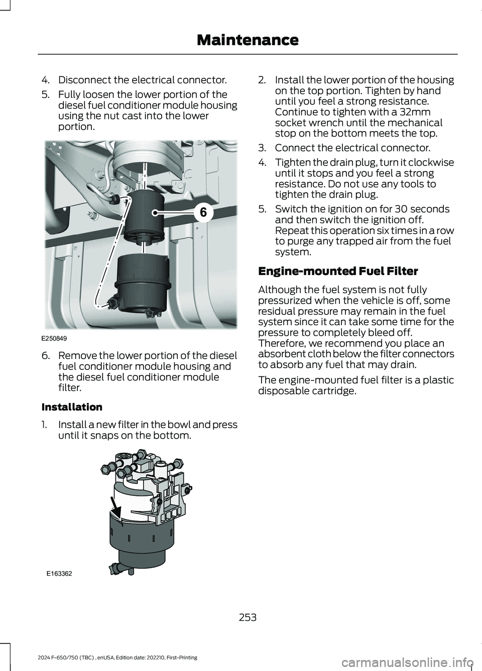
5.Fully loosen the lower portion of thediesel fuel conditioner module housingusing the nut cast into the lowerportion.
6.Remove the lower portion of the dieselfuel conditioner module housing andthe diesel fuel conditioner modulefilter.
Installation
1.Install a new filter in the bowl and pressuntil it snaps on the bottom.
2.Install the lower portion of the housingon the top portion. Tighten by handuntil you feel a strong resistance.Continue to tighten with a 32mmsocket wrench until the mechanicalstop on the bottom meets the top.
3.Connect the electrical connector.
4.Tighten the drain plug, turn it clockwiseuntil it stops and you feel a strongresistance. Do not use any tools totighten the drain plug.
5.Switch the ignition on for 30 secondsand then switch the ignition off.Repeat this operation six times in a rowto purge any trapped air from the fuelsystem.
Engine-mounted Fuel Filter
Although the fuel system is not fullypressurized when the vehicle is off, someresidual pressure may remain in the fuelsystem since it can take some time for thepressure to completely bleed off.Therefore, we recommend you place anabsorbent cloth below the filter connectorsto absorb any fuel that may drain.
The engine-mounted fuel filter is a plasticdisposable cartridge.
253
2024 F-650/750 (TBC) , enUSA, Edition date: 202210, First-PrintingMaintenanceE250849 E163362