2023 TOYOTA TUNDRA HYBRID ECU
[x] Cancel search: ECUPage 486 of 618

4886-3. Do-it-yourself maintenance
Owners Manual_USA_M0C052_en
removed using the pullout
tool.
4 Check if the fuse is blown.
Type A and B:
Replace the blown fuse with a new
fuse of an appropriate amperage
rating. The amperage rating can be
found on the fuse box lid.
Type C and D:
Contact your Toyota dealer.
Ty p e A
Normal fuse
Blown fuse
Ty p e B Normal fuse
Blown fuse
Type C
Normal fuse
Blown fuse
Type D
Normal fuse
Blown fuse
■After a fuse is replaced
●When installing the lid, make sure
that the tab is ins talled securely.
●If the lights do not turn on even
after the fuse has been replaced,
a bulb may need replacement.
●If the replaced fuse blows again,
have the vehicle inspected by
your Toyota dealer.
■If there is an ove rload in a cir-
cuit
The fuses are designed to blow, pro-
Page 489 of 618
4916-3. Do-it-yourself maintenance
Owners Manual_USA_M0C052_en
6
Maintenance and care
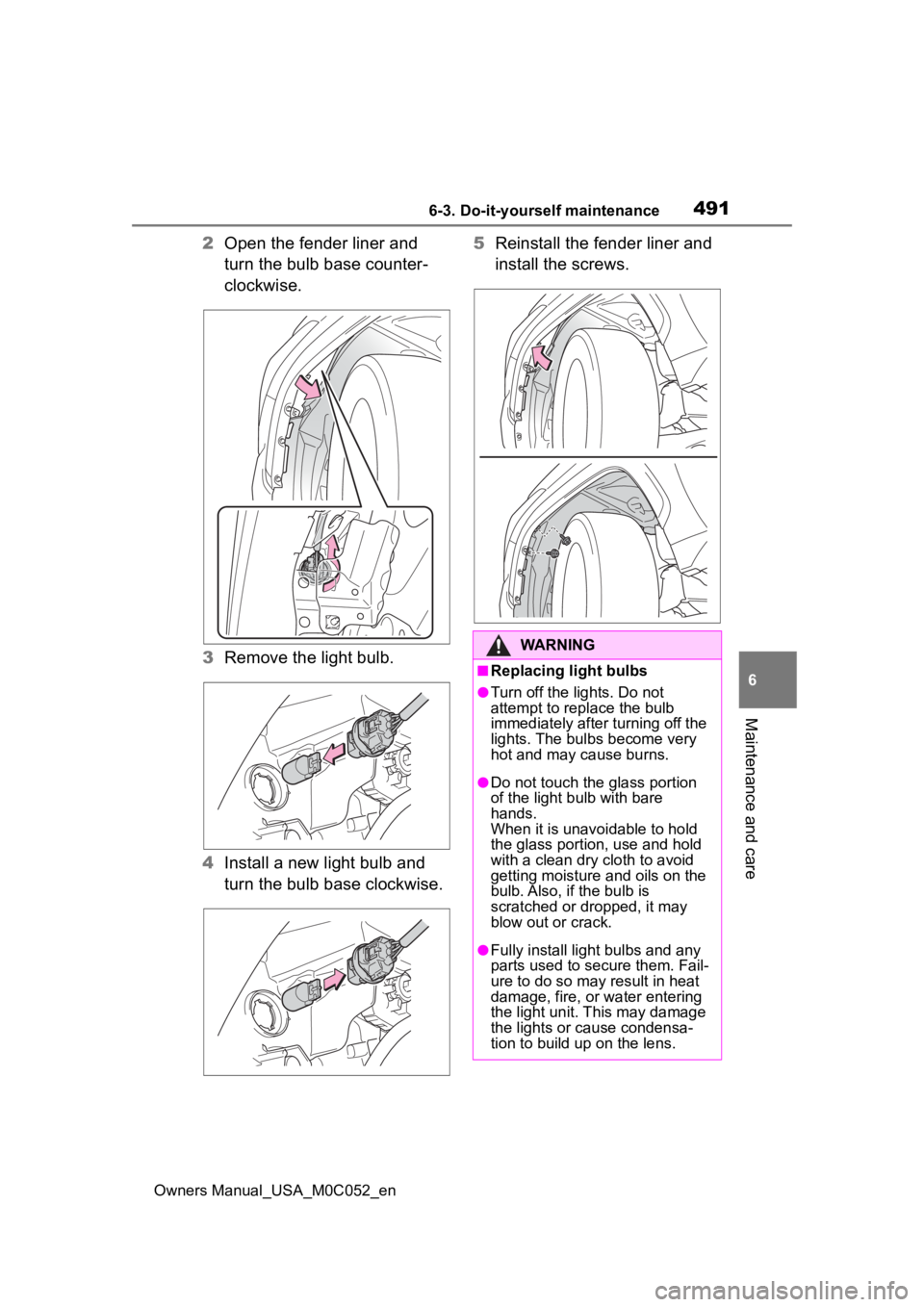
2 Open the fender liner and
turn the bulb base counter-
clockwise.
3 Remove the light bulb.
4 Install a new light bulb and
turn the bulb base clockwise. 5
Reinstall the fender liner and
install the screws.
WARNING
■Replacing light bulbs
●Turn off the lights. Do not
attempt to replace the bulb
immediately after turning off the
lights. The bulbs become very
hot and may cause burns.
●Do not touch the glass portion
of the light bulb with bare
hands.
When it is unavoidable to hold
the glass portion, use and hold
with a clean dry cloth to avoid
getting moisture and oils on the
bulb. Also, if the bulb is
scratched or dropped, it may
blow out or crack.
●Fully install light bulbs and any
parts used to secure them. Fail-
ure to do so may result in heat
damage, fire, or water entering
the light unit. This may damage
the lights or cause condensa-
tion to build up on the lens.
Page 492 of 618
4947-1. Essential information
Owners Manual_USA_M0C052_en
7-1.Essential information
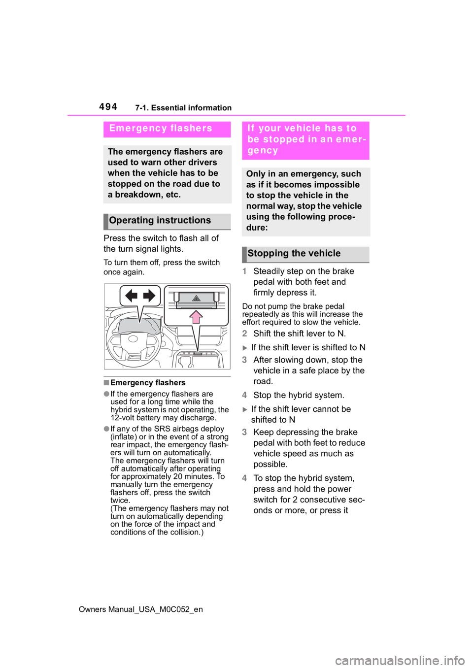
Press the switch to flash all of
the turn signal lights.
To turn them off, press the switch
once again.
■Emergency flashers
●If the emergency flashers are
used for a long time while the
hybrid system is not operating, the
12-volt battery may discharge.
●If any of the SRS airbags deploy
(inflate) or in the event of a strong
rear impact, the emergency flash-
ers will turn on automatically.
The emergency flashers will turn
off automatically after operating
for approximately 20 minutes. To
manually turn t he emergency
flashers off, press the switch
twice.
(The emergency flashers may not
turn on automatically depending
on the force of the impact and
conditions of the collision.)
1 Steadily step on the brake
pedal with both feet and
firmly depress it.
Do not pump the brake pedal
repeatedly as this will increase the
effort required to slow the vehicle.
2Shift the shift lever to N.
If the shift lever is shifted to N
3 After slowing down, stop the
vehicle in a safe place by the
road.
4 Stop the hybrid system.
If the shift lever cannot be
shifted to N
3 Keep depressing the brake
pedal with both feet to reduce
vehicle speed as much as
possible.
4 To stop the hybrid system,
press and hold the power
switch for 2 consecutive sec-
onds or more, or press it
Emergency flashers
The emergency flashers are
used to warn other drivers
when the vehicle has to be
stopped on the road due to
a breakdown, etc.
Operating instructions
If your vehicle has to
be stopped in an emer-
gency
Only in an emergency, such
as if it becomes impossible
to stop the vehicle in the
normal way, stop the vehicle
using the following proce-
dure:
Stopping the vehicle
Page 506 of 618
5087-2. Steps to take in an emergency
Owners Manual_USA_M0C052_en
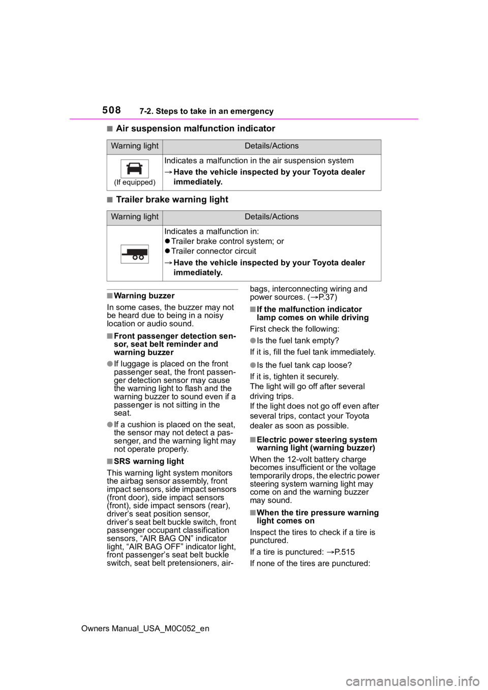
■Air suspension malfunction indicator
■Trailer brake warning light
■Warning buzzer
In some cases, the buzzer may not
be heard due to being in a noisy
location or audio sound.
■Front passenger detection sen-
sor, seat belt reminder and
warning buzzer
●If luggage is placed on the front
passenger seat, the front passen-
ger detection sensor may cause
the warning light to flash and the
warning buzzer to sound even if a
passenger is not sitting in the
seat.
●If a cushion is placed on the seat,
the sensor may n ot detect a pas-
senger, and the warning light may
not operate properly.
■SRS warning light
This warning light system monitors
the airbag sensor assembly, front
impact sensors, side impact sensors
(front door), side impact sensors
(front), side impact sensors (rear),
driver’s seat position sensor,
driver’s seat belt buckle switch, front
passenger occupant classification
sensors, “AIR BAG ON” indicator
light, “AIR BAG OFF” indicator light,
front passenger’s seat belt buckle
switch, seat belt pretensioners, air- bags, interconnecting wiring and
power sources. (
P. 3 7 )
■If the malfunction indicator
lamp comes on while driving
First check the following:
●Is the fuel tank empty?
If it is, fill the fuel tank immediately.
●Is the fuel ta nk cap loose?
If it is, tighten it securely.
The light will go off after several
driving trips.
If the light does not go off even after
several trips, con tact your Toyota
dealer as soon as possible.
■Electric power steering system
warning light (warning buzzer)
When the 12-volt battery charge
becomes insufficient or the voltage
temporarily drops, the electric power
steering system warning light may
come on and the warning buzzer
may sound.
■When the tire pressure warning
light comes on
Inspect the tires to check if a tire is
punctured.
If a tire is punctured: P. 5 1 5
If none of the tires are punctured:
Warning lightDetails/Actions
(If equipped)
Indicates a malfunction in the air suspension system
Have the vehicle inspecte d by your Toyota dealer
immediately.
Warning lightDetails/Actions
Indicates a malfunction in:
Trailer brake control system; or
Trailer connector circuit
Have the vehicle inspecte d by your Toyota dealer
immediately.
Page 514 of 618
5167-2. Steps to take in an emergency
Owners Manual_USA_M0C052_en
When replacing tires on a vehi-
cle with wheel lock nuts, use the
following procedures to remove
and install the wheel lock nuts.
The wheel lock key is stored in
the glove box. Always return the
wheel lock key to its original
position after use, so that it does not get lost. (
P.515)
■Removal
For ease of removal, the wheel
lock nut should always be the
first one loosened.
1 Place the wheel lock key on
top of the wheel lock nut,
turning until the wheel lock
key and wheel lock nut pat-
terns engage.
2 Place the wheel nut wrench
on the wheel lock key, and
while applying pressure on
the wheel lock key, loosen
the wheel lock nut.
■Installation
For ease of installation, the
wheel lock nut should always be
the last one tightened.
1 By hand, install a wheel lock
nut on each wheel.
2 Place the wheel lock key on
top of the wheel lock nut,
turning until the wheel lock
key and wheel lock nut pat-
terns engage.
3 Place the wheel nut wrench
on the wheel lock key, and
while applying pressure on
the wheel lock key, tighten
the wheel lock nut to the rec-
ommended torque.
WARNING
●Put the jack prope rly in its jack
point.
●Do not put any part of your body
under the vehicle while it is sup-
ported by the jack.
●Do not start the hybrid system
or drive the vehicle while the
vehicle is suppor ted by the jack.
●Do not raise the vehicle while
someone is inside.
●When raising the vehicle, do not
put an object on or under the
jack.
●Do not raise the vehicle to a
height greater than that required
to replace the tire.
●Use a jack stand if it is neces-
sary to get under the vehicle.
●When lowering the vehicle,
make sure that there is no-one
near the vehicle. If there are
people nearby, warn them
vocally before lowering.
■Using the jack handle
Insert the square head securely
until you hear a click to prevent
the extension parts from coming
apart unexpectedly.
Wheel lock nut (if
equipped)
Page 520 of 618
5227-2. Steps to take in an emergency
Owners Manual_USA_M0C052_en
4While raising, secure the tire,
taking care that the tire goes
straight up without catching
on any surrounding part, to
prevent it from flying forward
during a collision or sudden
braking.
Tightening torque:
34.7 ft•lbf (46.6 N•m, 4.8 kgf•m)
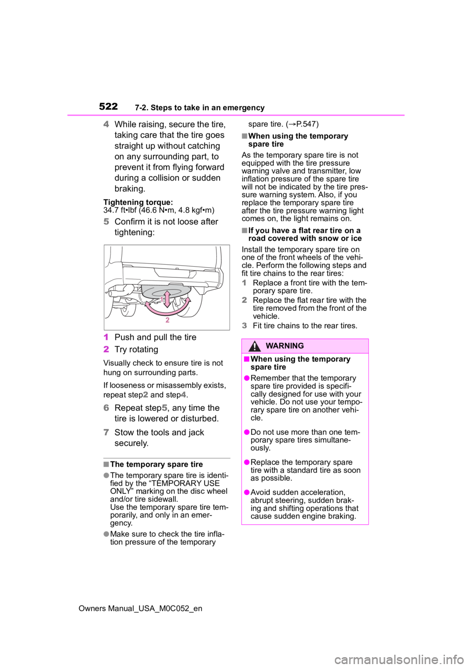
5Confirm it is not loose after
tightening:
1 Push and pull the tire
2 Try rotating
Visually check to ensure tire is not
hung on surrounding parts.
If looseness or misassembly exists,
repeat step 2 and step 4.
6 Repeat step5, any time the
tire is lowered or disturbed.
7 Stow the tools and jack
securely.
■The temporary spare tire
●The temporary spare tire is identi-
fied by the “TEMPORARY USE
ONLY” marking on the disc wheel
and/or tire sidewall.
Use the temporary spare tire tem-
porarily, and only in an emer-
gency.
●Make sure to check the tire infla-
tion pressure of the temporary spare tire. (
P.547)
■When using the temporary
spare tire
As the temporary spare tire is not
equipped with the tire pressure
warning valve and transmitter, low
inflation pressure of the spare tire
will not be indicated by the tire pres-
sure warning system. Also, if you
replace the temporary spare tire
after the tire pressure warning light
comes on, the light remains on.
■If you have a flat rear tire on a
road covered with snow or ice
Install the temporary spare tire on
one of the front w heels of the vehi-
cle. Perform the following steps and
fit tire chains to the rear tires:
1 Replace a front tire with the tem-
porary spare tire.
2 Replace the flat rear tire with the
tire removed from the front of the
vehicle.
3 Fit tire chains to the rear tires.
WARNING
■When using the temporary
spare tire
●Remember that t he temporary
spare tire provided is specifi-
cally designed for use with your
vehicle. Do not use your tempo-
rary spare tire on another vehi-
cle.
●Do not use more than one tem-
porary spare tires simultane-
ously.
●Replace the temporary spare
tire with a standa rd tire as soon
as possible.
●Avoid sudden acceleration,
abrupt steering, sudden brak-
ing and shifting operations that
cause sudden engine braking.
Page 529 of 618
5317-2. Steps to take in an emergency
Owners Manual_USA_M0C052_en
7
When trouble arises
Exclusive jump starting terminal (your vehicle)
Positive (+) battery terminal (second vehicle)
Negative (-) battery term inal (second vehicle)
Solid, stationary, unpainted metallic point away from the batte ry
and any moving parts as shown in the illustration
6 Start the engine of the sec-
ond vehicle. Increase the
engine speed slightly and
maintain at that level for
approximately 5 minutes to
recharge the 12-volt battery
of your vehicle.
7 Open and close any of the
doors of your vehicle with the
power switch OFF.
8 Maintain the engine speed of
the second vehicle and start
the hybrid system of your
vehicle by turning the power
switch to ON.
9 Once the vehicle’s hybrid
system has started, remove
the jumper cables in the
exact reverse order from
which they were connected.
10 When the engine cover
installing, reverse the step
removed.
11 Close the exclusive jump
starting terminal cover, and
reinstall the fuse box cover to
its original position.
Once the engine starts, have the
vehicle inspected at your Toyota
dealer as soon as possible.
■Starting the hybrid system
when the battery is discharged
The hybrid system cannot be started
by push-starting.
■To prevent 12-volt battery dis-
charge
●Turn off the headlights and the
audio system while the hybrid sys-
tem is off.
●Turn off any unnecessary electri-
cal components when the vehicle
is running at a low speed for an
extended period, such as in heavy
traffic.
■When the 12-volt battery is
removed or discharged
●Information stored in the ECU is
cleared. When the 12-volt battery
is depleted, have the vehicle
inspected at your Toyota dealer.
●Some systems may require initial-
ization. ( P.571)
■When removing the 12-volt bat-
tery terminals
When the 12-volt battery terminals
are removed, the information stored
in the ECU is cleared. Before
removing the 12-vo lt battery termi-
nals, contact you r Toyota dealer.
■Charging the 12-volt battery
The electricity stored in the 12-volt
battery will discha rge gradually even
when the vehicle i s not in use, due
to natural dischar ge and the drain-
ing effects of certain electrical appli-
ances. If the vehicle is left for a long
time, the 12-volt battery may dis-
charge, and the hybrid system may
be unable to start. (The 12-volt bat-
Page 530 of 618
5327-2. Steps to take in an emergency
Owners Manual_USA_M0C052_entery recharges aut
omatically while
the hybrid system is operating.)
■When recharging or replacing
the 12-volt battery
●In some cases, i t may not be pos-
sible to unlock the doors using the
smart key system when the 12-
volt battery is discharged. Use the
wireless remote control or the
mechanical key to lock or unlock
the doors.
●The hybrid system may not start
on the first attem pt after reinstall-
ing the 12-volt battery. In that
case, start the hy brid system in
the same manner as when the
electronic key does not operate
properly ( P.528). This is not a
malfunction, as the hybrid system
will start normally on the second
attempt.
●The power switch mode is memo-
rized by the vehicle. When the 12-
volt battery is reconnected, the
system will return to the mode it
was in before the 12-volt battery
was discharged. Before discon-
necting the 12-volt battery, turn
the power switch off.
If you are unsure what mode the
power switch was in before the
12-volt battery discharged, be
especially careful when recon-
necting the 12-volt battery.
●Some systems may require initial-
ization. ( P.571)
■When replacing the 12-volt bat-
tery
●Use a 12-volt battery that con-
forms to European regulations.
●Use a battery that the case size is
same as the previous one (LN2),
20 hours rate capacity (20HR) is
equivalent (55Ah) or greater, and
performance rating (CCA) is
equivalent (345A) or greater.
• If the sizes differ, the 12-volt bat- tery cannot be pr operly secured.
• If the 20 hour rate capacity is low,
even if the time period where the
vehicle is not used is a short time, the 12-volt battery may discharge
and hybrid system may not be
able to start.
●Use a ventilation type calcium bat-
tery
●Use a 12-volt battery with a han-
dle. If a 12-volt battery without a
handle is used, removal is more
difficult.
●When removing the 12-volt bat-
tery:
P.463
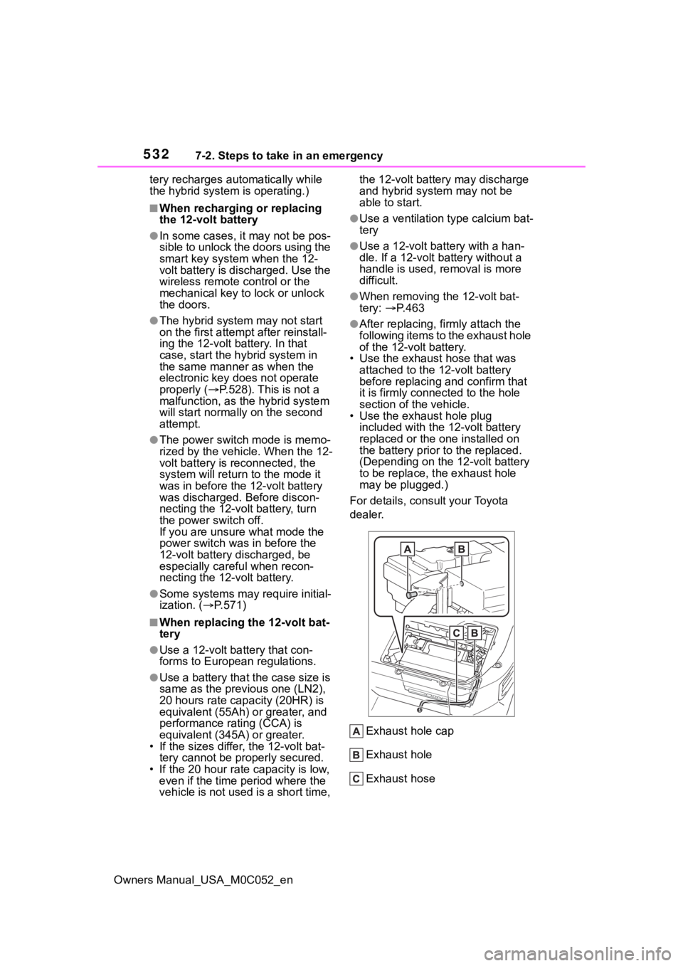
●After replacing, firmly attach the
following items to the exhaust hole
of the 12-volt battery.
• Use the exhaust hose that was
attached to the 1 2-volt battery
before replacing and confirm that
it is firmly connected to the hole
section of the vehicle.
• Use the exhaust hole plug
included with the 12-volt battery
replaced or the one installed on
the battery prior to the replaced.
(Depending on the 12-volt battery
to be replace, t he exhaust hole
may be plugged.)
For details, consult your Toyota
dealer.
Exhaust hole cap
Exhaust hole
Exhaust hose