Page 267 of 372
267
5
5
MOBILITY
MOBILITY
.5-1. MOBILITYRefueling ..................... 268
Wheels and tires ......... 270
Engine compartment ... 297
Operating materials..... 300
Maintenance ............... 308
Replacing components .................................. 311
Breakdown assistance .................................. 320
Care ............................ 330
Page 268 of 372

2685-1. MOBILITY
5-1.MOBILITY
This chapter describes all stan-
dard, country-specific and
optional features offered with
the series. It also describes fea-
tures and functions that are not
necessarily available in your
vehicle, e.g., due to the selected
options or country versions. This
also applies to safety-related
functions and systems. When
using these functions and sys-
tems, the applicable laws and
regulations must be observed.
Follow the fuel recommenda-
tion, refer to page 300, prior to
refueling.
When refueling, insert the filler
nozzle completely into the filler
pipe. Lifting up the fuel pump
nozzle during refueling causes:
Premature switching off.
Reduced return of the fuel
vapors.
The fuel tank is full when the
filler nozzle clicks off the first
time.
Make sure that the fuel cap is closed properly after refueling,
otherwise the emissions warn-
ing light may light up.
Follow safety regulations posted
at the gas station.
1
Briefly press the rear edge of
the fuel filler flap.
Refueling
Vehicle features and
options
Follow the following when
refueling
General information
Safety information
NOTICE
With a driving range of less than
30 miles/50 km the engine may
no longer have sufficient fuel.
Engine functions are not ensured
anymore. There is a risk of dam-
age to property. Refuel promptly.
NOTICE
Fuels are toxic and aggressive.
Overfilling of the fuel tank can
damage the fuel system. Painted
surfaces may be damaged by
contact with fuel. Escaping fuel
can harm the environment. There
is a risk of damage to property.
Avoid overfilling.
Fuel cap
Opening
Page 285 of 372

2855-1. MOBILITY
5
MOBILITY
into the power socket inside
the vehicle.
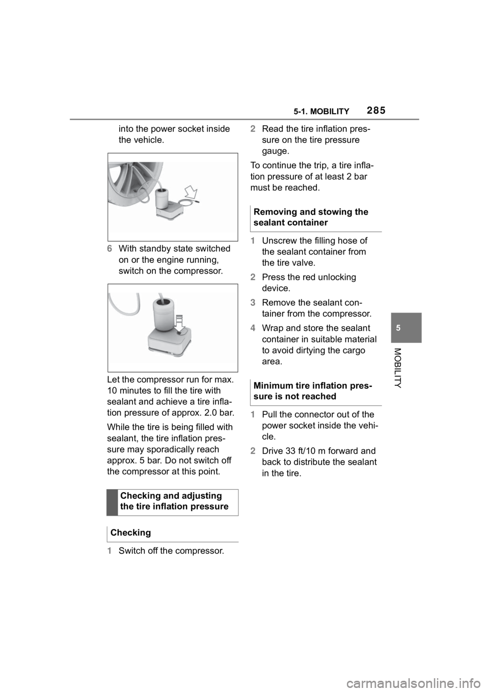
6 With standby state switched
on or the engine running,
switch on the compressor.
Let the compressor run for max.
10 minutes to fill the tire with
sealant and achieve a tire infla-
tion pressure of approx. 2.0 bar.
While the tire is being filled with
sealant, the tire inflation pres-
sure may sporadically reach
approx. 5 bar. Do not switch off
the compressor at this point.
1 Switch off the compressor. 2
Read the tire inflation pres-
sure on the tire pressure
gauge.
To continue the trip, a tire infla-
tion pressure of at least 2 bar
must be reached.
1 Unscrew the filling hose of
the sealant container from
the tire valve.
2 Press the red unlocking
device.
3 Remove the sealant con-
tainer from the compressor.
4 Wrap and store the sealant
container in suitable material
to avoid dirtying the cargo
area.
1 Pull the connector out of the
power socket inside the vehi-
cle.
2 Drive 33 ft/10 m forward and
back to distribute the sealant
in the tire.
Checking and adjusting
the tire inflation pressure
Checking
Removing and stowing the
sealant container
Minimum tire inflation pres-
sure is not reached
Page 286 of 372

2865-1. MOBILITY
3Screw the connection hose of
the compressor directly onto
the tire valve stem.
4 Insert the connector into the
power socket inside the vehi-
cle.
5 With standby state switched
on or the engine running,
switch on the compressor.
If a tire inflation pressure of at least
2 bar cannot be reached, contact
your Toyota dealer.
If a tire inflation pressure of at least
2 bar is reached, see Minimum tire
inflation pressure is reached.
6Unscrew the connection
hose of the compressor from
the tire valve.
7 Pull the connector out of the
power socket inside the vehi-
cle. 8
Stow the Mobility System in
the vehicle.
1 Unscrew the connection
hose of the compressor from
the tire valve.
2 Pull the connector out of the
power socket inside the vehi-
cle.
3 Stow the Mobility System in
the vehicle.
4 Immediately drive approx. 5
miles/10 km to ensure that
the sealant is evenly distrib-
uted in the tire.
Do not exceed a speed of 50
mph/80 km/h.
If possible, do no t drive at speeds
less than 12 mph/20 km/h.
1 Stop at a suitable location.
2 Screw the connection hose of
the compressor directly onto
the tire valve stem.
Minimum tire inflation pres-
sure is reached
Adjustment
Page 287 of 372

2875-1. MOBILITY
5
MOBILITY
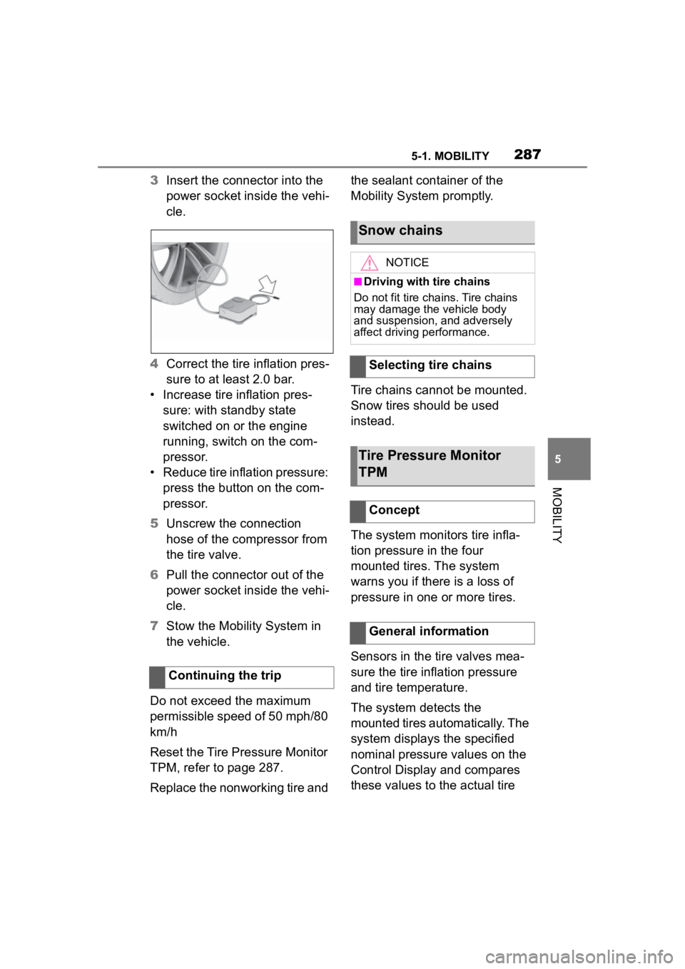
3Insert the connector into the
power socket inside the vehi-
cle.
4 Correct the tire inflation pres-
sure to at least 2.0 bar.
• Increase tire inflation pres- sure: with standby state
switched on or the engine
running, switch on the com-
pressor.
• Reduce tire inflation pressure: press the button on the com-
pressor.
5 Unscrew the connection
hose of the compressor from
the tire valve.
6 Pull the connector out of the
power socket inside the vehi-
cle.
7 Stow the Mobility System in
the vehicle.
Do not exceed the maximum
permissible speed of 50 mph/80
km/h
Reset the Tire Pressure Monitor
TPM, refer to page 287.
Replace the nonworking tire and the sealant container of the
Mobility System promptly.
Tire chains cannot be mounted.
Snow tires should be used
instead.
The system monitors tire infla-
tion pressure in the four
mounted tires. The system
warns you if there is a loss of
pressure in one or more tires.
Sensors in the tire valves mea-
sure the tire inflation pressure
and tire temperature.
The system detects the
mounted tires automatically. The
system displays the specified
nominal pressure values on the
Control Display and compares
these values to the actual tire
Continuing the trip
Snow chains
NOTICE
■Driving with tire chains
Do not fit tire chains. Tire chains
may damage the vehicle body
and suspension, and adversely
affect driving performance.
Selecting tire chains
Tire Pressure Monitor
TPM
Concept
General information
Page 297 of 372
2975-1. MOBILITY
5
MOBILITY
3Remove the adapter and
stow it after screwing on the
lug bolt.
This chapter describes all stan-
dard, country-specific and
optional features offered with
the series. It also describes fea-
tures and functions that are not
necessarily available in your
vehicle, e.g., due to the selected
options or country versions. This
also applies to safety-related
functions and systems. When
using these functions and sys-
tems, the applicable laws and
regulations must be observed.Engine compar tment
Vehicle features and
options
Page 298 of 372
2985-1. MOBILITY
1Filler neck for washer fluid
2 Jump-starting, negative battery terminal
3 Jump-starting, positive battery terminal
4 Oil filler neck
5 Coolant reservoir, auxiliary cooling
6 Coolant reservoir, engine
7 Vehicle identification number
Overview
Hood
Safety information
WARNING
Improperly executed work in the
engine compartment can damage
vehicle components and impair
vehicle functions. There is a risk
of an accident and damage to
property. Have work in the engine
compartment performed by your
Toyota dealer.
WARNING
The engine compartment accom-
modates moving components.
Certain components in the engine
compartment can also move with
the vehicle switched off, for
instance the radiator fan. There is
a risk of injury. Do not reach into
the area of moving parts. Keep
articles of clothing and hair away
from moving parts.
Page 300 of 372

3005-1. MOBILITY
This chapter describes all stan-
dard, country-specific and
optional features offered with
the series. It also describes fea-
tures that are not necessarily
available in your vehicle, for
instance, due to the selected
options or country versions. This
also applies to safety-related
functions and systems. When
using these functions and sys-
tems, the applicable laws and
regulations must be observed.
Depending on the region, many
gas stations sell fuel that has
been customized to winter or
summer conditions. Fuel that is
available in winter,for instance
helps make a cold start easier.
For the best fuel consumption,
the gasoline should be sul-
fur-free or very low in sulfur con-
tent.
Fuels that are marked on the gas pump as containing metal
must not be used.
Fuels with a maximum ethanol
content of 25 %, i. e. E10 or
E25, may be used for refueling.
To achieve nominal values for
mileage and consumption, fol-
low the specified fuel quality in
the sales literature.
Ethanol should meet the follow-
ing quality standards:
US: ASTM 4806–xx
CAN: CGSB-3.511–xx
xx: comply with the current valid
standard in each case.
The use of fuels of minimum
quality has no influence on the
service life of the engine.
Operating materials
Vehicle features and
options
Fuel recommendation
General information
Gasoline
General information
Safety information
WARNING
The use of poor-quality fuels may
result in harmful engine deposits
or damage. Additionally, problems
relating to drivability, starting and
stalling, especially under certain
environmental conditions such as
high ambient temperature and
high altitude, may occur.