2023 TOYOTA SUPRA engine
[x] Cancel search: enginePage 199 of 372

1993-1. CONTROLS
3
CONTROLS
This chapter describes all stan-
dard, country-specific and
optional features offered with
the series. It also describes fea-
tures and functions that are not
necessarily available in your
vehicle, e.g., due to the selected
options or country versions. This
also applies to safety-related
functions and systems. When
using these functions and sys-
tems, the applicable laws and
regulations must be observed.
ABS prevents locking of the
wheels during braking.
The vehicle maintains its steer-
ing power even during full brake
applications, which increases
the active safety.
ABS is operational every time
you start the engine.
Situations which the ABS can-
not operate sufficiently:
When entering a curve at an
excessively high rate of speed
In this case, even if the ABS oper-
ates, it cannot ope rate sufficiently
to avoid a possible dangerous situ-
ation. The driver is solely responsi-
ble for understanding their
surroundings and d riving at a safe
speed.
When you apply the brakes rap-
idly, the system automatically
produces the greatest possible
braking force boost. It reduces
the braking distance to a mini-
mum during emergency stop.
This system utilizes all of the
capabilities provided by the Anti-
lock Brake System ABS.
Do not reduce the pressure on
the brake pedal for the duration
of the emergency stop.
In combination with Dynamic
radar cruise control, this system
ensures that the brakes respond
even more rapidly when braking
in critical situations.
Driving stability con-
trol systems
Vehicle features and
options
Anti-lock Braking System
ABS
Brake assist
Adaptive brake assist
Page 200 of 372

2003-1. CONTROLS
This system supports driving off
on uphill grades.
1Hold the vehicle in place with
the foot brake.
2 Release the foot brake and
drive off without delay.
After the foot brake is released,
the vehicle is held in place for
approx. 2 seconds.
Depending on the vehicle load-
ing, the vehicle may roll back
slightly.
Within the physical limits, the
system helps to keep the vehicle
on a steady course by reducing
engine speed and by braking
the individual wheels.
VSC detects the following unsta-
ble driving conditions, for
instance:
Fishtailing, which can lead to
oversteering.
Loss of traction of the front
wheels, which can lead to
understeering.
Hill-start assist control
Concept
Driving off
VSC Vehicle Stability Con-
trol System
Concept
General information
Safety information
WARNING
The system cannot serve as a
substitute for the driver’s personal
judgment in assessing the traffic
situation. Based on the limits of
the system, it cannot inde-
pendently react to all traffic situa-
tions. There is a risk of accident.
Adjust driving style to traffic condi-
tions. Watch the surrounding traf-
fic situation closely, be ready to
take over steering and braking at
any time, and actively intervene
where appropriate.
WARNING
When driving with a roof load, for
instance with roof-mounted lug-
gage rack, the vehicle's center of
gravity is higher, which increases
the risk of the vehicle tipping in
critical driving sit uations. There is
a risk of accidents or risk of dam-
age to property. Do not deactivate
VSC Vehicle Stability Control Sys-
tem when driving with roof load.
Page 209 of 372

2093-1. CONTROLS
3
CONTROLSWith the proper equipment, the
value of the selected speed is
briefly displayed digitally.
Some system information can
also be displayed in the
Head-up Display.
The desired speed is also main-
tained downhill.
The speed may not be main-
tained on uphill grades if the
engine power is insufficient.
*: if equipped
Using this system, a desired
speed and a distance to a vehi-
cle ahead can be adjusted using
the buttons on the steering
wheel.
The system maintains the
desired speed on clear roads.
For this purpose, the vehicle
accelerates or brakes automati-
cally.
If a vehicle is driving ahead of
you, the system adjusts the
speed of your vehicle so that the
set distance to the vehicle
ahead is maintained. The speed
is adjusted as far as the given
situation allows.
Depending on the vehicle set-
tings, the characteristics of the
Cruise Control may change.
The distance can be adjusted in
several steps. For safety rea-
sons, it depends on the respec-
tive speed.
If the vehicle ahead of you
brakes to a halt, and then pro-
ceeds to drive again within a
brief period, the system is able
Displays in the instrument
cluster
Indicator light
Indicator light green:
system is active.
Gray indicator light: the
system has been inter-
rupted.
No indicator light: sys-
tem is switched off.
Status display
Displays in the Head-up
Display
The symbol is displayed
when the set desired
speed is reached.
System limits
Dynamic radar cruise
control with full-speed
range*
Concept
General information
Page 218 of 372

2183-1. CONTROLS
Drive attentively, and react to
the current traffic situation. If
necessary, intervene actively,
for instance by braking, steering
or evading.
The desired speed is also main-
tained downhill. The speed may
not be maintained on uphill
grades if the engine power is
insufficient.
When the systems in the vehicle
e.g., Speed Limit Info, detect a
change of the speed limit along
the route, this new speed value
ca be applied for the following
systems:
Manual Speed Limiter.
Cruise Control.
Dynamic radar cruise control
with full-speed range.
The speed value is suggested
as the new desired speed to be
applied. To apply the speed
value, the corresponding system
must be activated.
Via Toyota Supra Command:
1"My vehicle"
2 "Vehicle settings"
3 "Speed Assistant"
Engine power
Speed Limit Assist
Concept
Safety information
WARNING
The system cannot serve as a
substitute for the driver’s personal
judgment in assessing the traffic
situation. Based on the limits of
the system, it cannot inde-
pendently react to all traffic situa-
tions. There is a risk of accident.
Adjust driving style to traffic condi-
tions. Watch the surrounding traf-
fic situation closely, be ready to
take over steering and braking at
any time, and actively intervene
where appropriate.
WARNING
The desired speed can be incor-
rectly adjusted or called up by
mistake. There is a risk of an acci-
dent. Adjust the desired speed to
the traffic conditions. Watch traf-
fic closely and actively intervene
where appropriate.
Overview
Buttons on the steering
wheel
ButtonFunction
Apply suggested speed
manually.
Switching on/off and
adjusting
Page 221 of 372

2213-1. CONTROLS
3
CONTROLS
The system is controlled using
the following sensors:
• Ultrasonic sensors in the bumpers.
Additional information:
Sensors of the vehicle, refer to
page 42.
The system switches on auto-
matically in the following situa-
tions:
If selector lever position R is
engaged when the engine is
running.
Depending on the equipment
version: while approaching
detected obstacles if the
speed is slower than approx.
2.5 mph/4 km/h. The activa-
tion distance depends on the
situation in question.
You may switch automatic acti-
vation when obstacles are
detected on and off.
Via Toyota Supra Command:
1 "My vehicle"
2 "Vehicle settings"
3 "Parking"
4 Where applicable: "Automatic
Parking Sens. activation" 5
"Automatic Parking Sensors
activ."
Depending on equipment, an
additional camera view is also
switched on.
The system switches off when a
certain driving distance or speed
is exceeded.
Switch the system back on, if
needed.
On: the LED lights up.
Off: the LED goes out.
The rearview camera image is
displayed if the reverse gear is
engaged when pressing the
park assistance button.
Depending on the equipment
version, the system cannot be
switched off manually if the
reverse gear is engaged.
■General information
An intermittent tone indicates
when the vehicle is approaching
an object. For instance, if an
Sensors
Switching on/off
Switching on automatically
Automatic deactivation
during forward travel
Switching on/off manually
Press the park assistance
button.
WARNING
Signal tones
Page 226 of 372

2263-1. CONTROLS
The system is controlled by the
following sensors:
• Rearview camera.
Additional information:
Sensors of the vehicle, refer to
page 42.
The system is switched on auto-
matically if selector lever posi-
tion R is engaged when the
engine is running.
The system switches off when a
certain driving distance or speed is exceeded.
Switch the system back on, if
needed.
On: the LED lights up.
Off: the LED goes out.
The parking assistance func-
tions are shown on the Control
Display.
If the rearview camera view is
not displayed, change the view
via Toyota Supra Command:
1 If necessary, tilt the controller
to the side.
2 "Rear view camera"
The rearview camera image is
displayed.
The rearview camera is
switched on.
Keep the recording range of
the camera clear. Protruding
cargo or roof rack systems
can limit the detection range
of the camera.
Overview
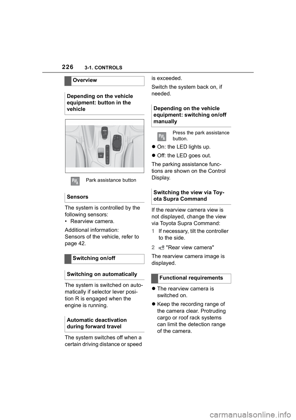
Depending on the vehicle
equipment: button in the
vehicle
Park assistance button
Sensors
Switching on/off
Switching on automatically
Automatic deactivation
during forward travel
Depending on the vehicle
equipment: switching on/off
manually
Press the park assistance
button.
Switching the view via Toy-
ota Supra Command
Functional requirements
Page 235 of 372

2353-1. CONTROLS
3
CONTROLS
Via Toyota Supra Command:
1"My Vehicle"
2 "Vehicle settings"
3 "Climate functions"
4 "Temperature adjustment,
upper body"
5 Set the desired temperature.
Do not rapidly switch between
different temperature settings.
Otherwise, the automatic air
conditioning will not have suffi-
cient time to adjust the set tem-
perature.
The air in the car's interior will
be cooled and dehumidified
and, depending on the tempera-
ture setting, warmed again.
The car's interior can only be
cooled with the drive-ready state
switched on. Air conditioning is switched on
with the engine running.
Depending on the weather, the
windshield and side windows
may fog up briefly when
drive-ready state is switched on.
The air conditioning is switched
on automatically with the AUTO
program.
When using the automatic air
conditioning, condensation
water develops and collects
underneath the vehicle.
The system is set to the lowest
temperature, optimum air flow
and recirculated-air mode with
the drive-ready state switched
on.
The function is available with
external temperatures above
approx. 32 °F/0 °C and with the
drive-ready state switched on.
Adjusting
Turn the dial clockwise
to increase the tempera-
ture and counterclock-
wise to decrease the
temperature.
Air conditioning
Concept
Switching on/off
Press the button.
Maximum cooling
Concept
General information
Page 238 of 372

2383-1. CONTROLS
quickly removed from the wind-
shield and the front side win-
dows.
The LED is illuminated with the
system switched on.
The air flow can be adjusted
manually with the system
switched on.
The function is available with the
engine running.
The rear window defroster
switches off automatically after a
certain period of time.
The microfilter removes dust
and pollen from the incoming air.
Have this filter changed during
vehicle maintenance, refer to
page 308.The air flow directions can be
individually adjusted.
The air flow directions can be
adjusted for direct or indirect
ventilation.
Open the vents and position
them to ensure effective climate
control.
The air flow is directed towards
the passengers. The air flow
heats or cools noticeably,
depending on the adjusted tem-
perature.
The air flow is not directed
towards the passengers. The
car's interior is warmed or
cooled indirectly, depending on
the set temperature.
Switching on/off
Press the button.
If there is any window
condensation, press the
button on the driver's
side or switch on the air
conditioning. Make sure
that air can flow to the
windshield.
Rear window defroster
Press the button. The
LED lights up.
Microfilter
Ventilation
Concept
Adjusting the ventilation
General information
Direct ventilation
Indirect ventilation