2023 NISSAN TITAN tow
[x] Cancel search: towPage 240 of 644
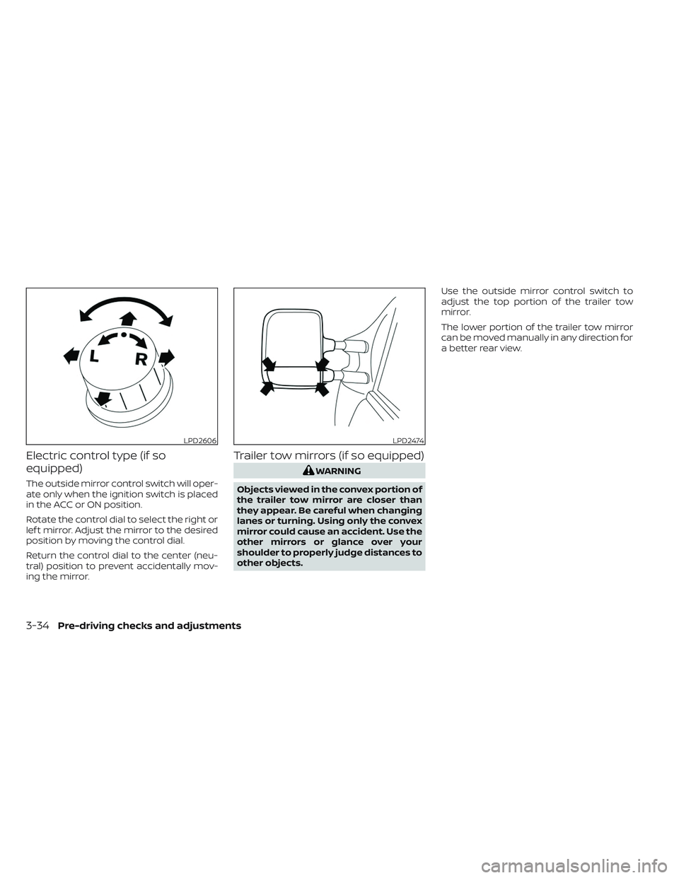
Electric control type (if so
equipped)
The outside mirror control switch will oper-
ate only when the ignition switch is placed
in the ACC or ON position.
Rotate the control dial to select the right or
lef t mirror. Adjust the mirror to the desired
position by moving the control dial.
Return the control dial to the center (neu-
tral) position to prevent accidentally mov-
ing the mirror.
Trailer tow mirrors (if so equipped)
WARNING
Objects viewed in the convex portion of
the trailer tow mirror are closer than
they appear. Be careful when changing
lanes or turning. Using only the convex
mirror could cause an accident. Use the
other mirrors or glance over your
shoulder to properly judge distances to
other objects. Use the outside mirror control switch to
adjust the top portion of the trailer tow
mirror.
The lower portion of the trailer tow mirror
can be moved manually in any direction for
a better rear view.
LPD2606LPD2474
3-34Pre-driving checks and adjustments
Page 241 of 644
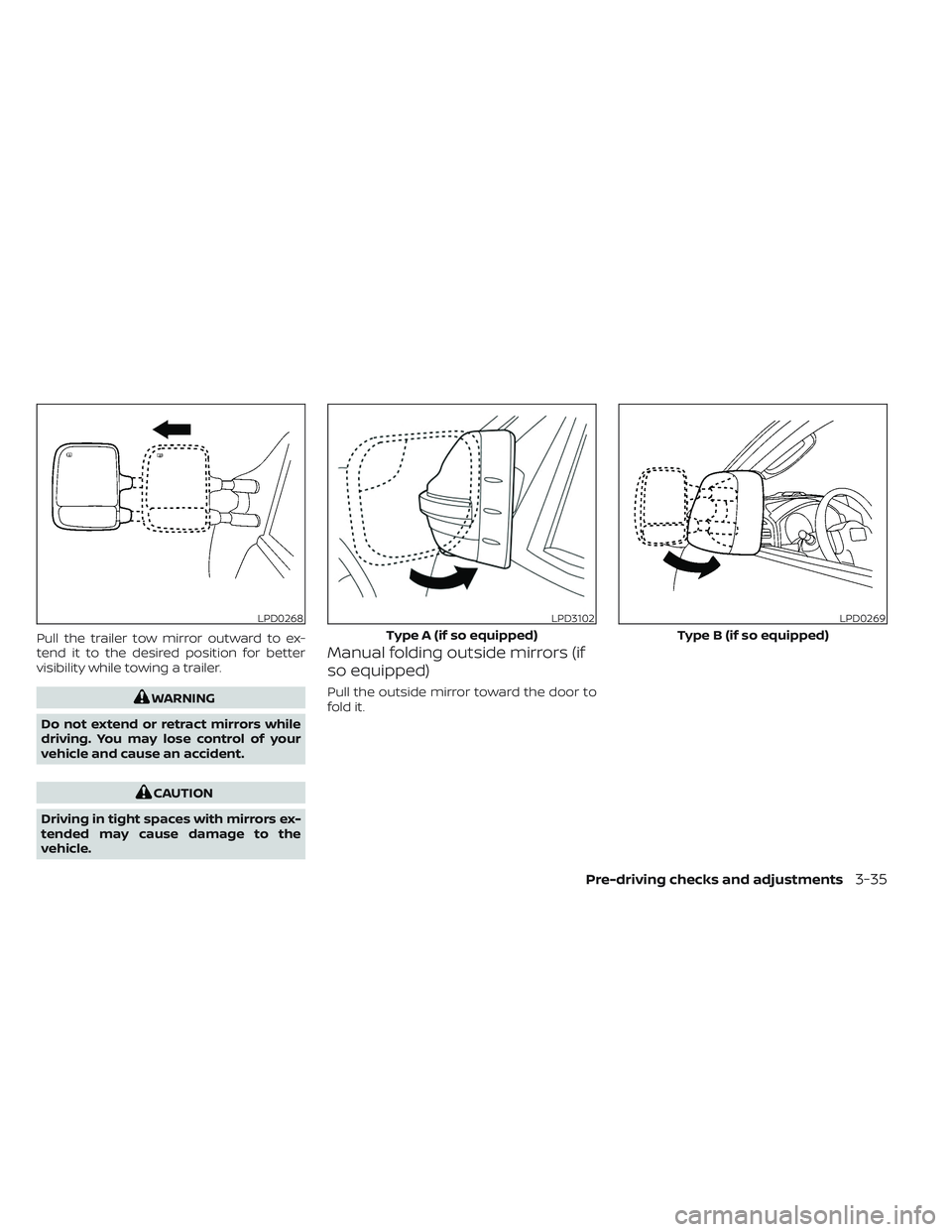
Pull the trailer tow mirror outward to ex-
tend it to the desired position for better
visibility while towing a trailer.
WARNING
Do not extend or retract mirrors while
driving. You may lose control of your
vehicle and cause an accident.
CAUTION
Driving in tight spaces with mirrors ex-
tended may cause damage to the
vehicle.
Manual folding outside mirrors (if
so equipped)
Pull the outside mirror toward the door to
fold it.
LPD0268LPD3102
Type A (if so equipped)
LPD0269
Type B (if so equipped)
Pre-driving checks and adjustments3-35
Page 246 of 644
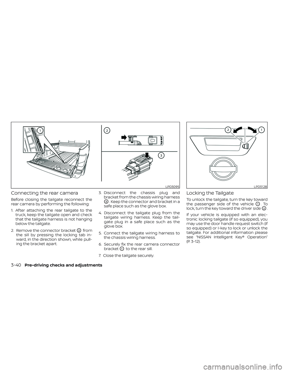
Connecting the rear camera
Before closing the tailgate reconnect the
rear camera by performing the following:
1. Af ter attaching the rear tailgate to thetruck, keep the tailgate open and check
that the tailgate harness is not hanging
below the tailgate.
2. Remove the connector bracket
O2from
the sill by pressing the locking tab in-
ward, in the direction shown, while pull-
ing the bracket apart. 3. Disconnect the chassis plug and
bracket from the chassis wiring harness
O3. Keep the connector and bracket in a
safe place such as the glove box.
4. Disconnect the tailgate plug from the tailgate wiring harness. Keep the tail-
gate plug in a safe place such as the
glove box.
5. Connect the tailgate wiring harness to the chassis wiring harness.
6. Securely fix the rear camera connector bracket
O1to the rear sill.
7. Close the tailgate securely.
Locking the Tailgate
To unlock the tailgate, turn the key toward
the passenger side of the vehicle
O1.To
lock, turn the key toward the driver side
O2.
If your vehicle is equipped with an elec-
tronic locking tailgate (if so equipped), you
may use the door handle request switch (if
so equipped) or I-key to lock or unlock the
tailgate. For additional information please
see “NISSAN Intelligent Key® Operation”
(P. 3-12).
LPD3095LPD3128
3-40Pre-driving checks and adjustments
Page 268 of 644
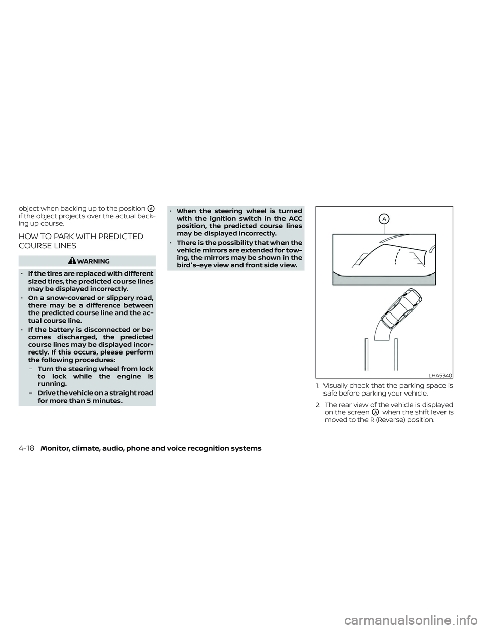
object when backing up to the positionOA
if the object projects over the actual back-
ing up course.
HOW TO PARK WITH PREDICTED
COURSE LINES
WARNING
• If the tires are replaced with different
sized tires, the predicted course lines
may be displayed incorrectly.
• On a snow-covered or slippery road,
there may be a difference between
the predicted course line and the ac-
tual course line.
• If the battery is disconnected or be-
comes discharged, the predicted
course lines may be displayed incor-
rectly. If this occurs, please perform
the following procedures:
– Turn the steering wheel from lock
to lock while the engine is
running.
– Drive the vehicle on a straight road
for more than 5 minutes. •
When the steering wheel is turned
with the ignition switch in the ACC
position, the predicted course lines
may be displayed incorrectly.
• There is the possibility that when the
vehicle mirrors are extended for tow-
ing, the mirrors may be shown in the
bird's-eye view and front side view.
1. Visually check that the parking space issafe before parking your vehicle.
2. The rear view of the vehicle is displayed on the screen
OAwhen the shif t lever is
moved to the R (Reverse) position.
LHA5340
4-18Monitor, climate, audio, phone and voice recognition systems
Page 274 of 644
WARNING
• Failure to follow the warnings and in-
structions for proper use of the Mov-
ing Object Detection system could
result in serious injury or death.
• The MOD system is not a substitute
for proper vehicle operation and is
not designed to prevent contact with
objects surrounding the vehicle.
When maneuvering, always use the
outside mirrors and rearview mirror
and turn and check the surroundings
to ensure it is safe to maneuver.
• The system is deactivated at speeds
above 6 mph (10 km/h). It is reacti-
vated at lower speeds.
• The MOD system is not designed to
detect surrounding stationary
objects.
The MOD system can inform the driver of
moving objects near the vehicle when
backing out of garages, maneuvering in
parking lots and in other such instances.
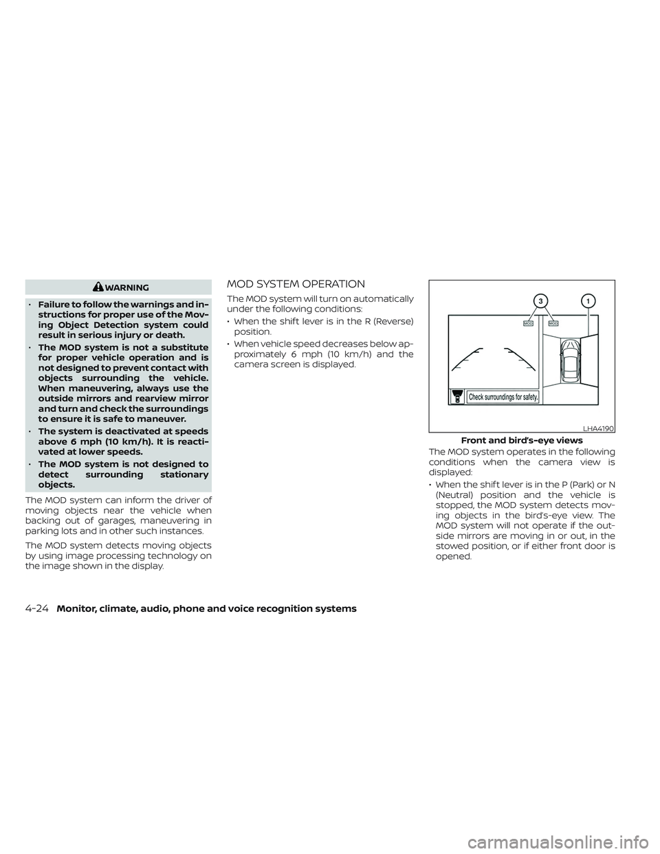
The MOD system detects moving objects
by using image processing technology on
the image shown in the display.MOD SYSTEM OPERATION
The MOD system will turn on automatically
under the following conditions:
• When the shif t lever is in the R (Reverse) position.
• When vehicle speed decreases below ap- proximately 6 mph (10 km/h) and the
camera screen is displayed.
The MOD system operates in the following
conditions when the camera view is
displayed:
• When the shif t lever is in the P (Park) or N(Neutral) position and the vehicle is
stopped, the MOD system detects mov-
ing objects in the bird’s-eye view. The
MOD system will not operate if the out-
side mirrors are moving in or out, in the
stowed position, or if either front door is
opened.
LHA4190
Front and bird’s-eye views
4-24Monitor, climate, audio, phone and voice recognition systems
Page 276 of 644
If the MOD system is turned off, the MOD
icon
O3is not displayed.
TURNING MOD ON AND OFF (if so
equipped)
Some vehicles include the option to allow
the MOD system to be turned on or off.
To turn the MOD system on or off:
1. Press the
orbutton on the
steering wheel to navigate to the “Set-
tings” screen.
2. Using the
buttons, select “Driver
Assistance” and press the ENTER button.
3. Select “Parking Aids” and press the EN- TER button.
4. Toggle ON or OFF “Moving Object” using the ENTER button.
You can also turn the MOD on or off by
pressing the Parking Aids system switch (if
so equipped).
MOD SYSTEM LIMITATIONS
WARNING
Listed below are the system limitations
for MOD. Failure to operate the vehicle
in accordance with these system limi-
tations could result in serious injury or
death.
• Do not use the MOD system when
towing a trailer. The system may not
function properly.
• Excessive noise (for example, audio
system volume or open vehicle win-
dow) will interfere with the chime
sound, and it may not be heard.
• The MOD system performance will be
limited according to environmental
conditions and surrounding objects
such as:
– When there is low contrast be-
tween background and the mov-
ing objects.
– When there is a blinking source of
light.
– When strong light such as another
vehicle’s headlight or sunlight is
present. –
When camera orientation is not in
its usual position, such as when a
mirror is folded.
– When there is dirt, water drops or
snow on the camera lens.
– When the position of the moving
objects in the display is not
changed.
• The MOD system might detect flow-
ing water droplets on the camera
lens, white smoke from the muffler,
moving shadows, etc.
• The MOD system may not function
properly depending on the speed, di-
rection, distance or shape of the
moving objects.
• If your vehicle sustains damage to
the parts where the camera is in-
stalled, leaving it misaligned or bent,
the sensing zone may be altered and
the MOD system may not detect ob-
jects properly.
• When the temperature is extremely
high or low, the screen may not dis-
play objects clearly. This is not a
malfunction.
4-26Monitor, climate, audio, phone and voice recognition systems
Page 339 of 644
WARNING
• The exhaust gas and the exhaust
system are very hot. Keep people,
animals or flammable materials
away from the exhaust system
components.
• Do not stop or park the vehicle over
flammable materials such as dry
grass, waste paper or rags. They may
ignite and cause a fire.
CAUTION
• Do not use leaded gasoline. Deposits
from leaded gasoline will seriously
reduce the three-way catalyst's abil-
ity to help reduce exhaust pollutants.
• Keep your engine tuned up. Malfunc-
tions in the ignition, fuel injection, or
electrical systems can cause overrich
fuel flow into the three-way catalyst,
causing it to overheat. Do not keep
driving if the engine misfires, or if no-
ticeable loss of performance or other
unusual operating conditions are de-
tected. Have the vehicle inspected
promptly. It is recommended that
you visit a NISSAN dealer for this
service. •
Avoid driving with an extremely low
fuel level. Running out of fuel could
cause the engine to misfire, damag-
ing the three-way catalyst.
• Do not race the engine while warm-
ing it up.
• Do not push or tow your vehicle to
start the engine.
TIRE PRESSURE MONITORING
SYSTEM (TPMS)
Each tire, including the spare (if provided),
should be checked monthly when cold and
inflated to the inflation pressure recom-
mended by the vehicle manufacturer on
the vehicle placard or tire inflation pressure
label. (If your vehicle has tires of a different
size than the size indicated on the vehicle
placard or tire inflation pressure label, you
should determine the proper tire inflation
pressure for those tires.)
As an added safety feature, your vehicle
has been equipped with a Tire Pressure
Monitoring System (TPMS) that illuminates
a low tire pressure telltale when one or
more of your tires is significantly under-
inflated. Accordingly, when the low tire
pressure telltale illuminates, you should
stop and check all your tires as soon as
possible, and inflate them to the proper pressure. Driving on a significantly under-
inflated tire causes the tire to overheat and
can lead to tire failure. Under-inflation also
reduces fuel efficiency and tire tread life,
and may affect the vehicle’s handling and
stopping ability.
Please note that the TPMS is not a substi-
tute for proper tire maintenance, and it is
the driver’s responsibility to maintain cor-
rect tire pressure, even if under-inflation
has not reached the level to trigger illumi-
nation of the TPMS low tire pressure telltale.
Your vehicle has also been equipped with a
TPMS malfunction indicator to indicate
when the system is not operating properly.
The TPMS malfunction indicator is com-
bined with the low tire pressure telltale.
When the system detects a malfunction,
the telltale will flash for approximately one
minute and then remain continuously illu-
minated. This sequence will continue upon
subsequent vehicle start-ups as long as
the malfunction exists. When the malfunc-
tion indicator is illuminated, the system
may not be able to detect or signal low tire
pressure as intended. TPMS malfunctions
may occur for a variety of reasons, includ-
ing the installation of replacement or alter-
nate tires or wheels on the vehicle that
Starting and driving5-5
Page 347 of 644
When the ignition switch is pushed without
depressing the brake pedal, the ignition
switch position will illuminate as follows:
Push center:
• Once to change to ACC.
• Two times to change to ON.
• Three times to return to OFF.
The ignition switch will automatically re-
turn to the LOCK position when any door is
either opened or closed with the switch in
the OFF position.
The ignition lock is designed so that the
ignition switch position cannot be placed
in the OFF position until the shif t lever is
moved to the P (Park) position.
When the ignition switch cannot be pushed
toward the OFF position, proceed as fol-
lows:
1. Move the shif t lever into the P (Park)position.
2. Push the ignition switch. The ignition switch position will change to the ON
position.
3. Push the ignition switch again to the OFF position. The shif t lever can be moved from the P
(Park) position if the ignition switch is in
the ON position and the brake pedal is
depressed.
If the battery of the vehicle is discharged,
the push-button ignition switch cannot
be moved from the LOCK position.
Some indicators and warnings for opera-
tion are displayed in the meter. For addi-
tional information, see “Vehicle information
display warnings and indicators” (P. 2-33).
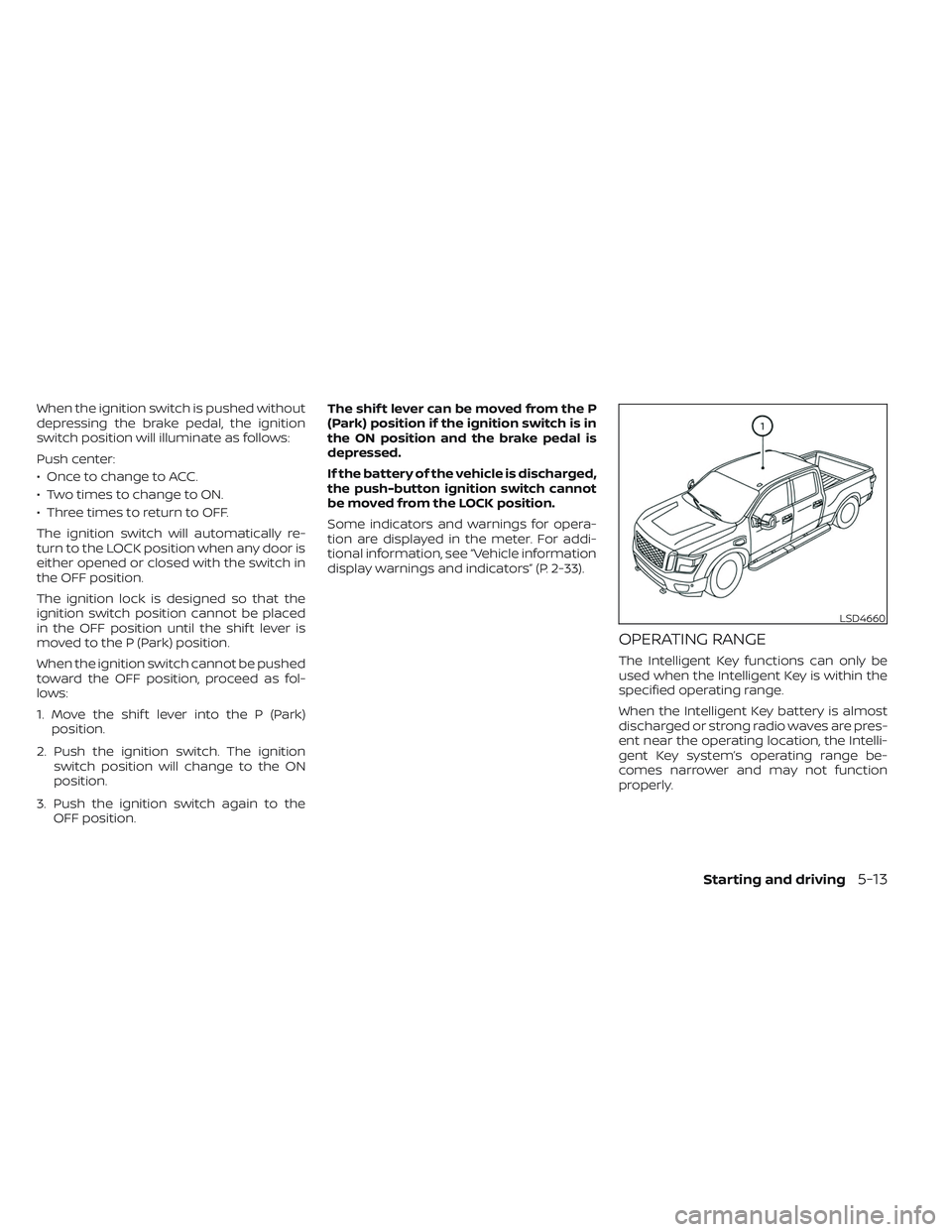
OPERATING RANGE
The Intelligent Key functions can only be
used when the Intelligent Key is within the
specified operating range.
When the Intelligent Key battery is almost
discharged or strong radio waves are pres-
ent near the operating location, the Intelli-
gent Key system’s operating range be-
comes narrower and may not function
properly.
LSD4660
Starting and driving5-13