2023 NISSAN KICKS instrument panel
[x] Cancel search: instrument panelPage 189 of 558
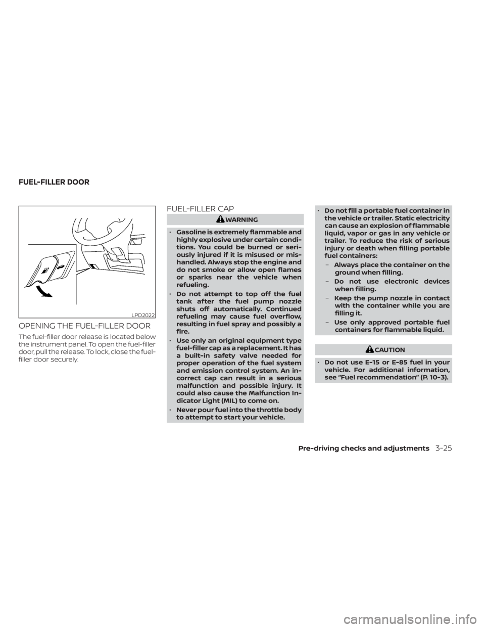
OPENING THE FUEL-FILLER DOOR
The fuel-filler door release is located below
the instrument panel. To open the fuel-filler
door, pull the release. To lock, close the fuel-
filler door securely.
FUEL-FILLER CAP
WARNING
• Gasoline is extremely flammable and
highly explosive under certain condi-
tions. You could be burned or seri-
ously injured if it is misused or mis-
handled. Always stop the engine and
do not smoke or allow open flames
or sparks near the vehicle when
refueling.
• Do not attempt to top off the fuel
tank af ter the fuel pump nozzle
shuts off automatically. Continued
refueling may cause fuel overflow,
resulting in fuel spray and possibly a
fire.
• Use only an original equipment type
fuel-filler cap as a replacement. It has
a built-in safety valve needed for
proper operation of the fuel system
and emission control system. An in-
correct cap can result in a serious
malfunction and possible injury. It
could also cause the Malfunction In-
dicator Light (MIL) to come on.
• Never pour fuel into the throttle body
to attempt to start your vehicle. •
Do not fill a portable fuel container in
the vehicle or trailer. Static electricity
can cause an explosion of flammable
liquid, vapor or gas in any vehicle or
trailer. To reduce the risk of serious
injury or death when filling portable
fuel containers:
– Always place the container on the
ground when filling.
– Do not use electronic devices
when filling.
– Keep the pump nozzle in contact
with the container while you are
filling it.
– Use only approved portable fuel
containers for flammable liquid.
CAUTION
• Do not use E-15 or E-85 fuel in your
vehicle. For additional information,
see “Fuel recommendation” (P. 10-3).
LPD2022
FUEL-FILLER DOOR
Pre-driving checks and adjustments3-25
Page 238 of 558
Temperature control dial
The temperature control dial allows you to
adjust the temperature of the outlet air. To
lower the temperature, turn the dial to the
lef t. To increase the temperature, turn the
dial to the right.
Air recirculation
Press theair recirculation button to
recirculate interior air inside the vehicle.
A/C (air conditioner) button
Start the engine, turn thefan speed
control dial to the desired position and
press the
button to turn on the air
conditioner. To turn off the air conditioner,
press the
button again.
The air conditioner cooling function op-
erates only when the engine is running.
Air flow control
Press thebutton to manually control
air flow and select the air outlet.
— Air flows from center and side
vents.
— Air flows from center and sidevents and foot outlets.
— Air flows mainly from footoutlets.
— Air flows from defroster andfoot outlets.
To turn system off
To turn off the heater and air conditioner,
press the ON-OFF button. Press the ON-
OFF button again, the system will turn on in
the mode which was used immediately
before the system was turned off.
Rear window and outside mirror
(if so equipped) defroster switch
For additional information, see “Rear win-
dow and outside mirror (if so equipped)
defroster switch” (P. 2-43).
Heated seat switches (if so
equipped)
For additional information, see “Heated
seat switches” (P. 2-52).
Heated steering wheel switch
(if so equipped)
For additional information, see “Heated
steering wheel switch” (P. 2-53).
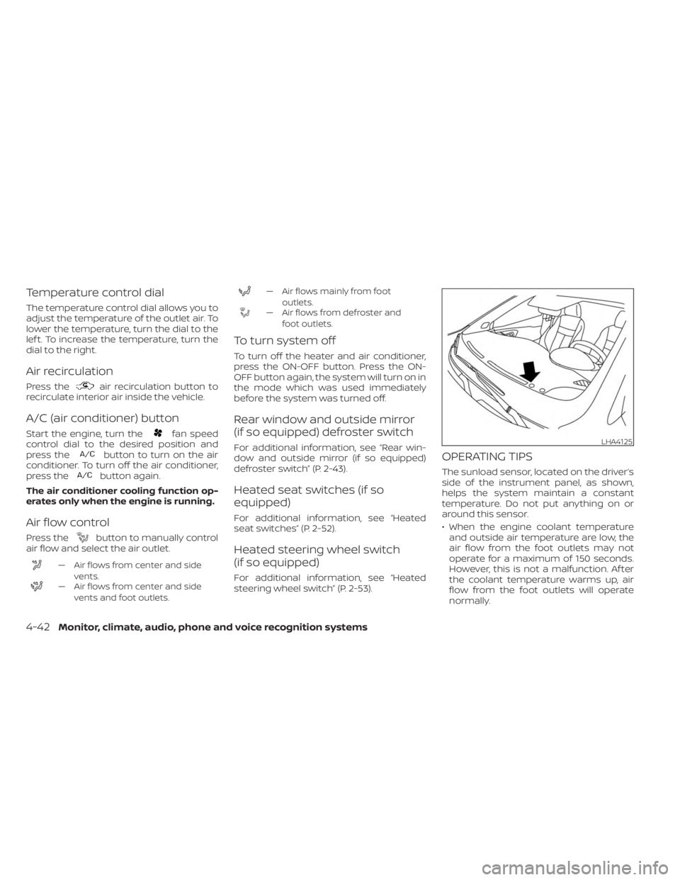
OPERATING TIPS
The sunload sensor, located on the driver’s
side of the instrument panel, as shown,
helps the system maintain a constant
temperature. Do not put anything on or
around this sensor.
• When the engine coolant temperatureand outside air temperature are low, the
air flow from the foot outlets may not
operate for a maximum of 150 seconds.
However, this is not a malfunction. Af ter
the coolant temperature warms up, air
flow from the foot outlets will operate
normally.
LHA4125
4-42Monitor, climate, audio, phone and voice recognition systems
Page 312 of 558
Af ter the above conditions have finished
and the necessary operating conditions
are satisfied, the LDW functions will resume.
SYSTEM MALFUNCTION
If the LDW system malfunctions, it will can-
cel automatically. The LDW indicator (or-
ange) or LDW indicator light will illuminate
in the instrument panel. If the LDW indicator
(orange) or LDW indicator light illuminates
in the instrument panel, pull off the road to
a safe location and stop the vehicle. Turn
the engine/motor off and restart the
engine/motor. If the LDW indicator (orange)
or LDW indicator light continues to illumi-
nate, have the LDW system checked. It is
recommended that you visit a NISSAN
dealer for this service.
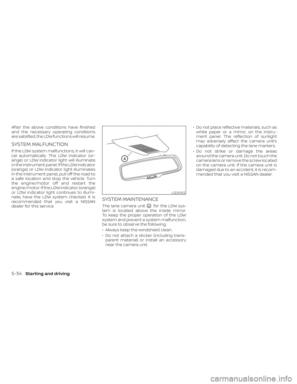
SYSTEM MAINTENANCE
The lane camera unitOAfor the LDW sys-
tem is located above the inside mirror.
To keep the proper operation of the LDW
system and prevent a system malfunction,
be sure to observe the following:
• Always keep the windshield clean.
• Do not attach a sticker (including trans- parent material) or install an accessory
near the camera unit. • Do not place reflective materials, such as
white paper or a mirror, on the instru-
ment panel. The reflection of sunlight
may adversely affect the camera unit’s
capability of detecting the lane markers.
• Do not strike or damage the areas around the camera unit. Do not touch the
camera lens or remove the screw located
on the camera unit. If the camera unit is
damaged due to an accident, it is recom-
mended that you visit a NISSAN dealer.
LSD5552
5-34Starting and driving
Page 335 of 558
WARNING
Do not use the cruise control when driv-
ing under the following conditions:
• When it is not possible to keep the
vehicle at a set speed.
• In heavy traffic or in traffic that varies
in speed.
• On winding or hilly roads.
•
On slippery roads (rain, snow, ice, etc.).
• In very windy areas.
Doing so could cause a loss of vehicle
control and result in an accident.
CRUISE CONTROL OPERATIONS
The cruise control allows driving at a speed
between 25 - 89 mph (40 - 144 km/h) without
keeping your foot on the accelerator pedal.
To turn on the cruise control, push the
CRUISE ON/OFF switch. The CRUISE indica-
tor light or
indicator in the instrument
panel comes on.
To set cruising speed, accelerate the ve-
hicle to the desired speed, push the SET–
switch and release it. The SET indicator
light or
indicator in the instrument
panel comes on. Take your foot off the ac-
celerator pedal. Your vehicle maintains the
set speed. •
To pass another vehicle, depress the ac-
celerator pedal. When you release the
pedal, the vehicle returns to the previ-
ously set speed.
• The vehicle may not maintain the set speed when going up or down steep hills.
If this happens, drive without the cruise
control.
To cancel the preset speed, use one of the
following three methods:
• Push the CANCEL switch; the CRUISE indi- cator light or
indicator in the instru-
ment panel goes out.
• Tap the brake pedal; the CRUISE indicator light or
indicator goes out.
• Push the CRUISE ON/OFF switch. The CRUISE indicator light or
indicator in
the instrument panel goes out.
The cruise control is automatically can-
celed and the CRUISE indicator light or
indicator in the instrument panel goes out
if:
• You depress the brake pedal while push- ing the RES+ or SET– switch. The preset
speed is deleted from memory.
• The vehicle slows down more than 8 mph (13 km/h) below the set speed.
• You move the shif t lever to N (Neutral). To reset at a faster cruising speed,
use
one of the following three methods:
• Depress the accelerator pedal. When the vehicle attains the desired speed, push
and release the SET– switch.
• Push and hold the RES+ switch. When the vehicle attains the speed you desire, re-
lease the switch.
• Push and release the RES+ switch. Each time you do this, the set speed increases
by about 1 mph (1.6 km/h).
To reset at a slower cruising speed, use
one of the following three methods:
• Lightly tap the brake pedal. When the ve- hicle attains the desired speed, push the
SET– switch and release it.
• Push and hold the SET– switch. Release the switch when the vehicle slows to the
desired speed.
• Push and release the SET– switch. Each time you do this, the set speed decreases
by about 1 mph (1.6 km/h).
To resume the preset speed, push and
release the RES+ switch. The vehicle re-
turns to the last set cruising speed when
the vehicle speed is over 25 mph (40 km/h).
Starting and driving5-57
Page 412 of 558
BRAKE ASSIST
When the force applied to the brake pedal
exceeds a certain level, the Brake Assist is
activated generating greater braking force
than a conventional brake booster even
with light pedal force.
WARNING
The Brake Assist is only an aid to assist
braking operation and is not a collision
warning or avoidance device. It is the
driver’s responsibility to stay alert,
drive safely and be in control of the ve-
hicle at all times. The VDC system uses various sensors to
monitor driver inputs and vehicle motion.
Under certain driving conditions, the VDC
system helps to perform the following
functions:
• Controls brake pressure to reduce wheel
slip on one slipping drive wheel so power
is transferred to a non-slipping drive
wheel on the same axle.
• Controls brake pressure and engine out- put to reduce drive wheel slip based on
vehicle speed (traction control function).
• Controls brake pressure at individual wheels and engine output to help the
driver maintain control of the vehicle in
the following conditions:– Understeer (vehicle tends to not follow the steered path despite increased
steering input)
– Oversteer (vehicle tends to spin due to certain road or driving conditions)
The VDC system can help the driver to
maintain control of the vehicle, but it can-
not prevent loss of vehicle control in all driv-
ing situations. When the VDC system operates, the
indicator light in the instrument panel
flashes so note the following:
• The road may be slippery or the system
may determine some action is required
to help keep the vehicle on the steered
path.
• You may feel a pulsation in the brake pedal and hear a noise or vibration from
under the hood. This is normal and indi-
cates that the VDC system is working
properly.
• Adjust your speed and driving to the road conditions.
For additional information, see “Slip indica-
tor light” (P. 2-21) and ”Vehicle Dynamic Con-
trol (VDC) OFF indicator light” (P. 2-21).
If a malfunction occurs in the system, the
indicator light comes on in the instru-
ment panel. The VDC system automatically
turns off when these indicator lights are on.
The VDC OFF switch, or the vehicle infor-
mation display, is used to turn off the VDC
system. The
indicator light and the
Automatic Emergency Braking (AEB) sys-
tem warning light or the AEB with Pedes-
trian Detection system warning light illumi-
nate to indicate the VDC system is off.
VEHICLE DYNAMIC CONTROL (VDC)
SYSTEM
5-134Starting and driving
Page 471 of 558
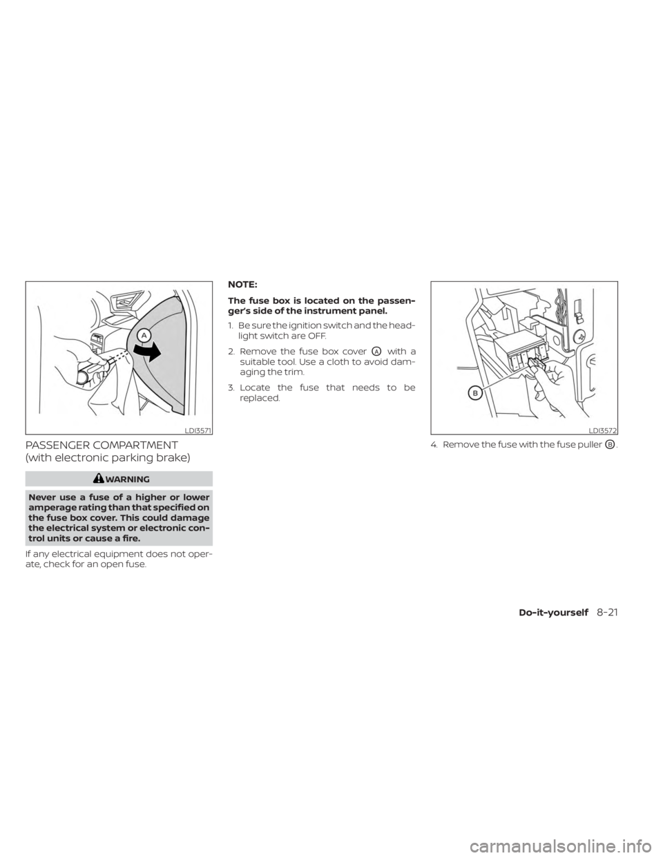
PASSENGER COMPARTMENT
(with electronic parking brake)
WARNING
Never use a fuse of a higher or lower
amperage rating than that specified on
the fuse box cover. This could damage
the electrical system or electronic con-
trol units or cause a fire.
If any electrical equipment does not oper-
ate, check for an open fuse.
NOTE:
The fuse box is located on the passen-
ger’s side of the instrument panel.
1. Be sure the ignition switch and the head- light switch are OFF.
2. Remove the fuse box cover
OAwith a
suitable tool. Use a cloth to avoid dam-
aging the trim.
3. Locate the fuse that needs to be replaced.
4. Remove the fuse with the fuse puller
OB.
LDI3571LDI3572
Do-it-yourself8-21
Page 547 of 558
11 Index
A
Active Ride Control (ARC).........5-138Air bag (See supplemental restraint
system).....................1-41Air bag system
Front (See supplemental front impact air
bag system)
................1-49Air bag warning labels............1-62Air bag warning light.........1-63, 2-15Air bag warning light,
supplemental..............1-63, 2-15Air cleaner housing filter..........8-15Air conditionerAir conditioner operation.....4-35, 4-41Air conditioner specification label. .10-12Air conditioner system refrigerant
recommendations............10-7Air conditioner system refrigerant and oil
recommendations............10-7Heater and air conditioner.......4-40Heater and air conditioner controls. .4-41Servicing air conditioner........4-43Air flow charts................4-36Alarm system (See vehicle security
system)................... .2-38Anchor point locations...........1-24Antenna....................4-62Anti-lock Braking System (ABS).....5-132Antifreeze...................5-145Audio system.................4-43
AM radio operation............4-50AM radio reception............4-44AM/FM radio............4-48, 4-50Auxiliary (AUX) devices operation. . .4-52Bluetooth® audio.............4-59FM radio operation............4-51FM radio reception............4-44iPod® Player................4-56iPod® player operation.........4-56Radio................... .4-43Steering wheel audio control
switch....................4-62USB Connections.............4-54USB interface...............4-53Autolight switch...............2-45Automatic
Automatic power window switch. . .2-73Automatic anti-glare inside mirror. . . .3-29Automatic brake hold............5-25Automatic door locks.............3-5Automatic Emergency Braking (AEB). .5-88Automatic Emergency Braking (AEB) with
Pedestrian Detection............5-98
B
Battery.................5- 145, 8-11Charge warning light...........2-14Battery replacement............8-22Key fob...................8-22
NISSAN Intelligent Key®.........8-23Before starting the engine.........5-15Belt (See drive belt)..............8-13Blind Spot Warning (BSW)..........5-35Blind Spot Warning (BSW) switch.....2-53Bluetooth® audio..............4-59Bluetooth® hands-free phone
system.................... .4-66Bluetooth® connections.........4-79Connecting procedure..........4-71Phone indicators.............4-70Text messaging..............4-76Voice commands.............4-72Booster seats.................1-37Brake
Anti-lock Braking System (ABS). . . .5-132Brake fluid................. .8-9Brake light (See stop light).......8-26Brake system...............5-132Brake warning light............2-13Brake wear indicators.......2-23,8-18Parking brake operation.........5-22Self-adjusting brakes...........8-17Brake Assist.................5-134Brake fluid................... .8-9Brake system................5-132Brakes.....................8-17Break-in schedule.............5-128Brightness control
Instrument panel.............2-50Brightness/contrast button.........4-7
Page 548 of 558
Bulb check/instrument panel........2-13Bulb replacement...............8-26
C
Capacities and recommended
fuel/lubricants.................10-2Car phone or CB radio............4-66Cargo
(See vehicle loading information).....10-14Cargo cover................. .2-66Chassis control................5-137Check tire pressure..............2-36Child restraint with top tether strap. . . .1-24Child restraints........1-17,1-18,1-19,1-21LATCH (Lower Anchors and Tethers for
CHildren) System..............1-21Precautions on child
restraints.........1-19,1-26,1-33, 1-38Top tether strap anchor point
locations...................1-24Child safety rear door lock..........3-6Cleaning exterior and interior......7-2,7-4Clock set.................... .4-5Cold weather driving............5-145Console box..................2-64Continuously Variable Transmission
(CVT).......................5-17Continuously Variable Transmission (CVT)
fluid..................... .8-9Driving with Continuously Variable
Transmission (CVT).............5-17
Transmission shif t selector lock
release....................5-20Control panel buttons.............4-3Brightness/contrast button........4-7Controls
Audio controls (steering wheel).....4-62Heater and air conditioner controls. .4-41Heater and air conditioner controls
(automatic)................ .4-40Heater and air conditioner controls
(manual).................. .4-32Coolant
Capacities and recommended
fuel/lubricants
...............10-2Changing engine coolant.........8-5Checking engine coolant level......8-5Corrosion protection..............7-7Cruise control................ .5-56Cup holders................. .2-64
D
Daytime Running Light System......2-49Defroster switch
Rear window and outside mirror defroster
switch
.............2-43, 4-34, 4-42Rear window defroster switch.....2-43Dimensions and weights..........10-9Dimmer switch for instrument panel. . .2-50DisplayInformation display............2-24Display controls (see control panel
buttons).................... .4-3
Door locks....................3-4Door open warning light...........2-14Drive belt....................8-13Drive Systems OFF switch..........2-54Driving
Cold weather driving...........5-145Driving with Continuously Variable
Transmission (CVT).............5-17Precautions when starting and
driving.................... .5-4Driving the vehicle...............5-17
E
Eco Drive Report................2-10Economy - fuel................5-129Emergency call (SOS) button........2-57Emergency engine shutoff.......5-13,6-2Emission control information label. . . .10-11Emission control system warranty. . . .10-21Engine
Before starting the engine........5-15Capacities and recommended
fuel/lubricants...............10-2Changing engine coolant.........8-5Changing engine oil............8-6Changing engine oil filter.........8-6Checking engine coolant level......8-5Checking engine oil level.........8-5Engine compartment check
locations.................. .8-3Engine cooling system...........8-4Engine oil...................8-5
11-2