Page 25 of 396

GETTING TO KNOW YOUR VEHICLE23
NOTE:DO NOT grab the door handle when pushing the door
handle lock button. This could unlock the door(s).
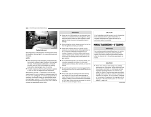
DO NOT Grab The Door Handle When Locking
The vehicle doors can also be locked by using the lock
button located on the vehicle’s interior door panel.
To Unlock/Enter The Swing Gate
The swing gate Passive Entry unlock feature is built into
the swing gate handle. With a valid Passive Entry key fob
within 5 ft (1.5 m) of the swing gate handle, grab the swing
gate handle to unlock the swing gate automatically, and
pull the swing gate to open.
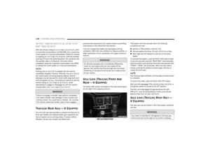
Swing Gate Passive Entry Lock Button
To Lock The Swing Gate
With a valid Passive Entry key fob within 5 ft (1.5 m) of the
swing gate handle, pushing the Passive Entry lock button
will lock the vehicle doors and the swing gate.
NOTE:
After pushing the door handle button, you must wait
two seconds before you can lock or unlock the doors,
using any Passive Entry door handle. This is done to
allow you to check if the vehicle is locked by pulling the
door handle without the vehicle unlocking.
If Passive Entry is disabled using the Uconnect
Settings, the key fob protection described in
"Frequency Operated Button Integrated Key
(FOBIK-Safe)" remains active/functional.
The Passive Entry system will not operate if the key fob
battery is depleted
Úpage 381.
AUTOMATIC DOOR LOCKS —
I
F EQUIPPED
The Automatic Door Lock feature default condition is
enabled. When enabled, the door locks will lock
automatically when the vehicle's speed exceeds 15 mph
(24 km/h). The Automatic Door Lock feature can be
enabled or disabled by an authorized dealer per written
request of the customer. Please see an authorized dealer
for service.
CHILD-PROTECTION DOOR LOCK
S
YSTEM — REAR DOORS
To provide a safer environment for small children riding in
the rear seats, the rear doors are equipped with a
Child-Protection Door Lock system.
To use the system, open each rear door, use a flat-blade
screwdriver (or mechanical key) and rotate the dial to the
lock or unlock position.
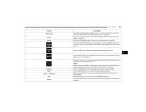
Child-Protection Door Lock Function
2
23_JL_OM_EN_USC_t.book Page 23
Page 26 of 396

24GETTING TO KNOW YOUR VEHICLE
NOTE:
When the Child-Protection Door Lock system is
engaged, the door can be opened only by using the
outside door handle even though the inside door lock
is in the unlocked position.
After disengaging the Child-Protection Door Lock
system, always test the door from the inside to make
certain it is in the unlocked position.
After engaging the Child-Protection Door Lock system,
always test the door from the inside to make certain it
is in the locked position.
For emergency exit with the system engaged, move the
lock lever rearward (located on the door trim panel),
lower the window and open the door with the outside
door handle.
NOTE:Always use this device when carrying children. After
engaging the child lock on both rear doors, check for
effective engagement by trying to open a door with the
internal handle. Once the Child-Protection Door Lock
system is engaged, it is impossible to open the doors from
inside the vehicle. Before getting out of the car, be sure to
check that there is no one left inside.
FRONT DOOR REMOVAL
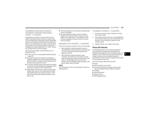
Door Removal Warning Label
Outside rearview mirrors are mounted on the doors. If you
choose to remove the doors, see an authorized dealer for
a replacement cowl-mounted outside mirror. Federal law
requires outside mirrors on vehicles for on-road use.
NOTE:
Doors are heavy; use caution when removing them.
Hinge pin can break if overtightened during door rein -
stall (Max Torque: 7.5 ft· lb / 10 N·m). For off-road
driving tips, see
Úpage 178.
When front doors are removed, the message “Blind
Spot Alert Temporarily Unavailable” will display in the
instrument cluster display. Power Mirrors and Power
Door Locks will also be unavailable.
To remove the front doors, proceed as follows:
1. Roll down the glass window to prevent any damage.
2. Remove the hinge pin screws from the upper and lower outside hinges (using a #T50 Torx head driver).
WARNING!
Avoid trapping anyone in a vehicle in a collision.
Remember that the rear doors can only be opened from
the outside when the Child-Protection locks are
engaged (locked).
WARNING!
Do not drive your vehicle on public roads with the doors
removed as you will lose the protection they can
provide. This procedure is furnished for use during
off-road operation only. Failure to follow this warning
can result in death or serious personal injury.
WARNING!
All occupants must wear seat belts during off-road
operation with doors removed. For off-road driving
tips, see
Úpage 178.
Do not store detached doors inside of the vehicle, as
they may cause personal injury in the event of an
accident.
23_JL_OM_EN_USC_t.book Page 24
Page 27 of 396
GETTING TO KNOW YOUR VEHICLE25
NOTE:The hinge pin screws and nuts can be stowed in the rear
cargo tray located under the rear load floor.
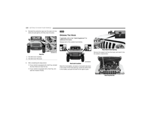
Hinge Pin Screw
3. Remove the plastic wiring access door under the
instrument panel by sliding the plastic panel along
the door frame toward the seats until the tabs are
detached.
Wiring Access Door
NOTE:Do not force open; this will break the plastic cover.
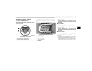
4. Pull up on the red locking tab to unlock the wiring harness.
Closed Wiring Harness
5. Push and hold down the black security tab under the wiring harness, and lift the harness lever into the
open position.
Open Wiring Harness
6. With the wiring harness open, pull straight downward
on the wiring connector to unplug. Store the wiring
connector in the lower door basket.
1 – Red Locking Tab
2 – Wiring Harness Lever
1 – Wiring Harness Lever (Open Position)
2 – Black Security Tab
2
23_JL_OM_EN_USC_t.book Page 25
Page 28 of 396

26GETTING TO KNOW YOUR VEHICLE
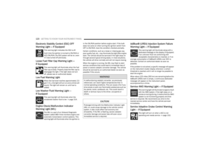
7. With the door in the open position, remove the check
bolt from the door check attachment on the bodyside
(using a #T40 Torx head driver).
NOTE:Keep the check arm in the extended position for easier
reinstallation. See note below if the check arm gets
pushed into the door while the door is off.
Door Check Arm
8. With the door open, lift the door with the help of another person, to clear the hinge pins from their
hinges and remove the door.
To Install The Front Doors
1. Locate the upper and lower hinge pins on the door, and lower them into the body hinges on the vehicle.
NOTE:The upper hinge pin is longer, which can be used to assist
in guiding the door into place during installation.
Hinge Pin Locations
2. With the door in the open position, align the door check bracket with the hole on the bodyside. Insert
the check screw and tighten using a #40 Torx head
driver to 19.9 ft· lb (27.0 N·m).
NOTE:If the check arm is stuck inside the door, follow these
instructions to install the check arm:
a. Insert the check arm screw into the check arm bracket. Ensure the screw is in the correct orientation.
b. Slowly pull on the screw to draw the check arm out until you encounter increased resistance. Do not attempt to
pull the check arm all the way out.
c. While sitting inside the vehicle, hold the door partially closed and insert the screw into the hole on the body.
d. Using your fingers, turn the screw clockwise at least two full turns. Gently pull on the screw to ensure it is secure.
e. Using the door handle, slowly push the door open. The check arm will be pulled out of the door. You may hear
the check arm pop against the screw.
f. Fully tighten the screw as instructed.
3. Insert the upper and lower hinge pin screws into the
body hinges. Tighten the screws using a #T50 Torx
head driver to 3.8 ft· lb / 5.2 N·m.
WARNING!
To avoid personal injury be sure to keep your arms,
hands, fingers and all objects clear of the check arm
area during the removal and installation procedures.
CAUTION!
Do not close the door before reattaching the door
check to the body. Damage may occur to the door
check.
Do not overtighten Torx fasteners, damage to the
vehicle’s parts will occur.
Hinge pins can break if overtightened during door
install (Max Torque: 6.0 ft· lb/8.1 N·m).
23_JL_OM_EN_USC_t.book Page 26
Page 29 of 396

GETTING TO KNOW YOUR VEHICLE27
Replacing The Wiring Connector Into The Wiring Harness
To reinstall the wiring connector on the vehicle’s door into
the harness just inside the vehicle, proceed as follows:
NOTE:Make sure there is plenty of slack on the wiring connector
during installation. Close the door slightly to provide more
slack if needed.
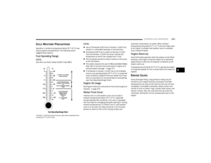
1. With light finger pressure, seat the wiring connector
straight
into the wiring harness until the wiring
harness lever starts to lower with the latching pin.
Connecting The Wiring Harness
2. After the harness lever has started to move with the pressure of seating the wiring connector, continue by
lowering the wiring harness lever to the fully closed
position.
Fully Closed Position
3. Push the red locking tab downward to lock into place.
4. Attach the cloth strap of the door onto the metal hook just inside the vehicle.
Cloth Strap Attachment
5. Replace wiring access doors.
REAR DOOR REMOVAL
(FOUR-DOOR MODELS)
1 — Seat Connector Straight Into Harness
2 — Wiring Harness Lever Starts To Lower
CAUTION!
Failure to correctly reconnect the wiring connector into
the harness will result in damage that is not covered by
the New Vehicle Warranty.
1 — Metal Hook
2 — Cloth Strap
WARNING!
Do not drive your vehicle on public roads with the doors
removed as you will lose the protection they can
provide. This procedure is furnished for use during
off-road operation only. Failure to follow this warning
can result in death or serious personal injury.
2
23_JL_OM_EN_USC_t.book Page 27
Page 30 of 396

28GETTING TO KNOW YOUR VEHICLE
Door Removal Warning Label
NOTE:
Doors are heavy; use caution when removing them.
Hinge pin can break if overtightened during door rein -
stall (Max Torque: 7.5 ft· lb / 10 N·m). For off-road
driving tips, see
Úpage 178. To remove the rear doors, proceed as follows:
1. Roll down the glass window to prevent any damage.
2. Remove the hinge pin screws from the upper and
lower outside hinges (using a #T50 Torx head driver).
NOTE:The hinge pin screws and nuts can be stowed in the rear
cargo tray located under the rear load floor.
Hinge Pin Screw
3. Slide the front seat(s) fully forward.
4. Pry open and remove the plastic wiring access door from the bottom of the B-pillar.
Wiring Access Door
5. Unplug the wiring connector.
NOTE:Squeeze the tab on the base of the wiring harness. This
will unlock the connector tab, allowing the wiring
connector to be unplugged.
Wiring Connector
WARNING!
All occupants must wear seat belts during off-road
operation with doors removed. For off-road driving
tips, see
Úpage 178.
Do not store detached doors inside of the vehicle, as
they may fly around and cause personal injury or
death in the event of a sudden stop, rough terrain, or
a collision.
23_JL_OM_EN_USC_t.book Page 28
Page 31 of 396

GETTING TO KNOW YOUR VEHICLE29
6. With the door in the open position, remove the check
bolt from the door check attachment on the body
(using a #T40 Torx head driver).
NOTE:Keep the check arm in the extended position for easier
reinstallation.
Door Check Arm
7. With the door open, lift the door with the help of another person, to clear the hinge pins from their
hinges and remove the door.
To reinstall the door(s), perform the previous steps in the
reverse order.
NOTE:The upper hinge has a longer pin, which can be used to
assist in guiding the door into place when reinstalling.
DOOR OFF MIRROR KIT — IF EQUIPPED
If equipped with the Door Off Mirror Kit, exterior rearview
mirrors can be installed on to the upper body door hinges
after the front doors have been removed.
Use this QR code to access your digital
experience.
Door Off Mirror
To install the Door Off Mirrors, proceed as follows:
1. Remove both front doors
Ú
page 24.
2. Remove the cowl bolt closest to the door opening using a #40 Torx head driver, and store in a safe
location.
Cowl Bolt Location
WARNING!
All occupants must wear seat belts during off-road
operation with doors removed. For off-road driving
tips, see
Úpage 178.
Do not store detached doors inside of the vehicle, as
they may fly around and cause personal injury or
death in the event of a sudden stop, rough terrain, or
a collision.
2
23_JL_OM_EN_USC_t.book Page 29
Page 32 of 396

30GETTING TO KNOW YOUR VEHICLE
3. Push the mirror bracket forward onto the A-pillar,
making sure to align the bottom of the bracket with
the upper door hinge, and the hole from the removed
cowl bolt.
Push Bracket Onto A-pillar
4. Place the bracket bushing behind the mirror bracket (over the cowl bolt hole), then insert the bracket bolt
into the mirror bracket, through the bracket bushing.
Attaching Mirror Bracket To The Vehicle
5. Insert the hinge shoulder bolt through the bottom of the upper door hinge up into the mirror bracket, then
rotate the bracket knob toward the rear of the vehicle
to secure the mirror bracket to the A-pillar.
Attaching Mirror Bracket To The Vehicle
6. Tighten both the bracket bolt and the hinge shoulder bolt with a #40 Torx head driver. Recommended
torque specification for the bracket bolt is 6 ft-lb
(8 N·m), and 7.5 ft-lb (10 N·m) for the hinge shoulder bolt.
1 — Bracket Bushing
2 — Bracket Bolt1 — Bracket Knob
2 — Hinge Shoulder Bolt
23_JL_OM_EN_USC_t.book Page 30