2023 DODGE CHARGER ignition
[x] Cancel search: ignitionPage 144 of 292
142MULTIMEDIA
HELP COMMAND
If you need assistance at any prompt, or if you want to
know your options at any prompt, say “Help” following the
beep.
To activate the Uconnect Phone from idle, simply push the
Phone button (if active) on your steering wheel and say a
command or say “Help”. All Phone sessions begin with a
push of the VR button or the Phone button.
CANCEL COMMAND
At any prompt, after the beep, you can say “Cancel” and
you will be returned to the main menu.
You can also push the VR button or Phone button on your
steering wheel when the system is listening for a
command and be returned to the main or previous menu.
PAIR (LINK) UCONNECT PHONE TO A MOBILE
PHONE
Use this QR code to access your digital
experience.
To begin using your Uconnect Phone,
you must pair your compatible
Bluetooth®-enabled mobile phone.
Mobile phone pairing is the process of
establishing a wireless connection
between a cellular phone and the
Uconnect system.
To complete the pairing process, you will need to
reference your mobile phone’s manual. Please visit
UconnectPhone.com for complete mobile phone
compatibility information.
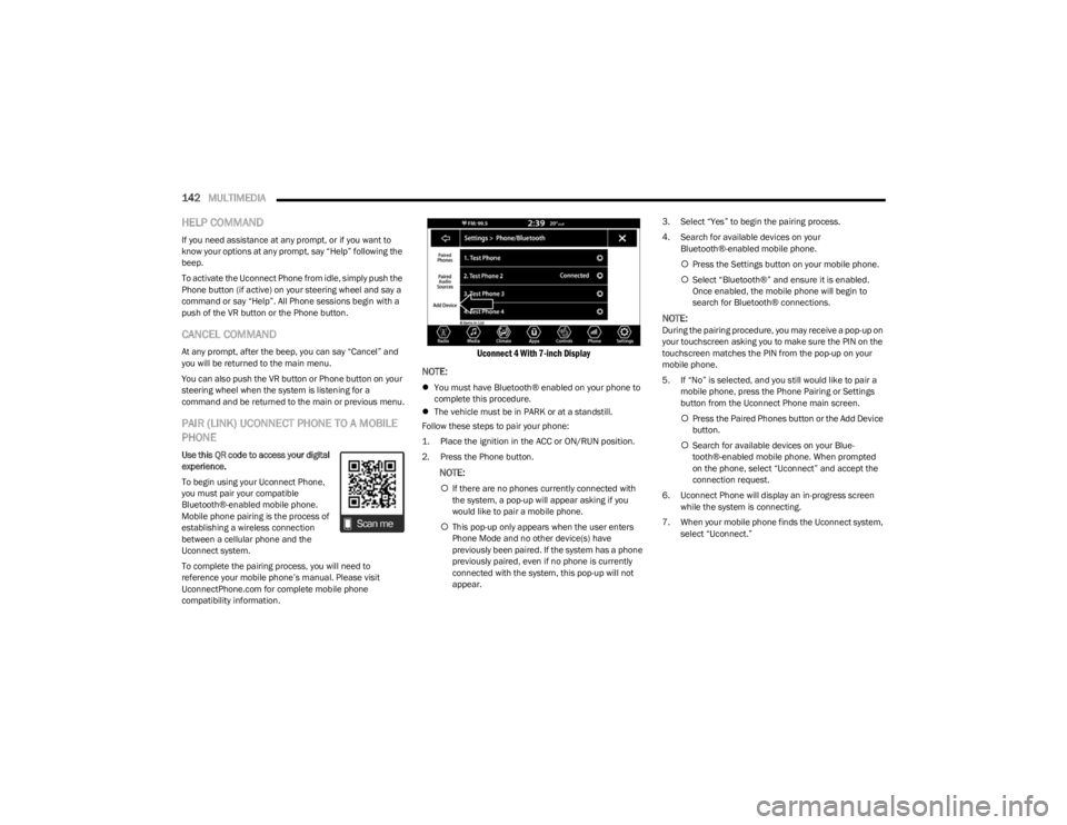
Uconnect 4 With 7-inch Display
NOTE:
You must have Bluetooth® enabled on your phone to
complete this procedure.
The vehicle must be in PARK or at a standstill.
Follow these steps to pair your phone:
1. Place the ignition in the ACC or ON/RUN position.
2. Press the Phone button.
NOTE:
If there are no phones currently connected with
the system, a pop-up will appear asking if you
would like to pair a mobile phone.
This pop-up only appears when the user enters
Phone Mode and no other device(s) have
previously been paired. If the system has a phone
previously paired, even if no phone is currently
connected with the system, this pop-up will not
appear. 3. Select “Yes” to begin the pairing process.
4. Search for available devices on your
Bluetooth®-enabled mobile phone.
Press the Settings button on your mobile phone.
Select “Bluetooth®” and ensure it is enabled.
Once enabled, the mobile phone will begin to
search for Bluetooth® connections.
NOTE:During the pairing procedure, you may receive a pop-up on
your touchscreen asking you to make sure the PIN on the
touchscreen matches the PIN from the pop-up on your
mobile phone.
5. If “No” is selected, and you still would like to pair a
mobile phone, press the Phone Pairing or Settings
button from the Uconnect Phone main screen.
Press the Paired Phones button or the Add Device
button.
Search for available devices on your Blue -
tooth®-enabled mobile phone. When prompted
on the phone, select “Uconnect” and accept the
connection request.
6. Uconnect Phone will display an in-progress screen while the system is connecting.
7. When your mobile phone finds the Uconnect system, select “Uconnect.”
23_LD_OM_EN_USC_t.book Page 142
Page 149 of 292
MULTIMEDIA147
MAKING A SECOND CALL WHILE CURRENT
CALL IS IN PROGRESS
You can place a call on hold by pressing the Hold button
on the Phone main screen, then dial a number from the
keypad (if supported by your mobile phone), recent calls,
SMS Inbox or from the phonebooks.
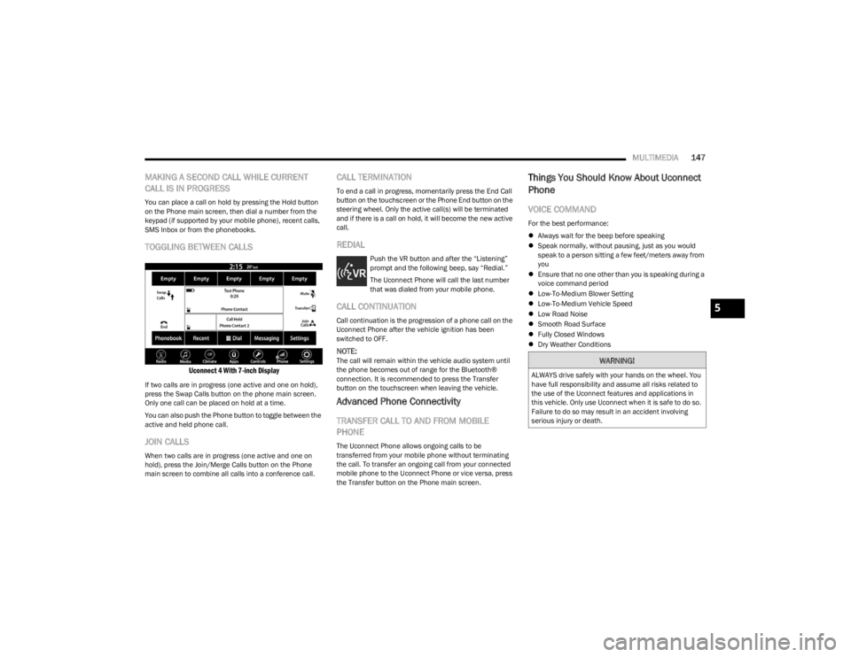
TOGGLING BETWEEN CALLS
Uconnect 4 With 7-inch Display
If two calls are in progress (one active and one on hold),
press the Swap Calls button on the phone main screen.
Only one call can be placed on hold at a time.
You can also push the Phone button to toggle between the
active and held phone call.
JOIN CALLS
When two calls are in progress (one active and one on
hold), press the Join/Merge Calls button on the Phone
main screen to combine all calls into a conference call.
CALL TERMINATION
To end a call in progress, momentarily press the End Call
button on the touchscreen or the Phone End button on the
steering wheel. Only the active call(s) will be terminated
and if there is a call on hold, it will become the new active
call.
REDIAL
Push the VR button and after the “Listening”
prompt and the following beep, say “Redial.”
The Uconnect Phone will call the last number
that was dialed from your mobile phone.
CALL CONTINUATION
Call continuation is the progression of a phone call on the
Uconnect Phone after the vehicle ignition has been
switched to OFF.
NOTE:The call will remain within the vehicle audio system until
the phone becomes out of range for the Bluetooth®
connection. It is recommended to press the Transfer
button on the touchscreen when leaving the vehicle.
Advanced Phone Connectivity
TRANSFER CALL TO AND FROM MOBILE
PHONE
The Uconnect Phone allows ongoing calls to be
transferred from your mobile phone without terminating
the call. To transfer an ongoing call from your connected
mobile phone to the Uconnect Phone or vice versa, press
the Transfer button on the Phone main screen.
Things You Should Know About Uconnect
Phone
VOICE COMMAND
For the best performance:
Always wait for the beep before speaking
Speak normally, without pausing, just as you would
speak to a person sitting a few feet/meters away from
you
Ensure that no one other than you is speaking during a
voice command period
Low-To-Medium Blower Setting
Low-To-Medium Vehicle Speed
Low Road Noise
Smooth Road Surface
Fully Closed Windows
Dry Weather Conditions
WARNING!
ALWAYS drive safely with your hands on the wheel. You
have full responsibility and assume all risks related to
the use of the Uconnect features and applications in
this vehicle. Only use Uconnect when it is safe to do so.
Failure to do so may result in an accident involving
serious injury or death.
5
23_LD_OM_EN_USC_t.book Page 147
Page 151 of 292

MULTIMEDIA149
Siri® Eyes Free — If Equipped
When used with your Apple® iPhone® connected to your
vehicle via Bluetooth®, Siri lets you use your voice to send
text messages, select media, place phone calls and much
more. Siri uses your natural language to understand what
you mean and responds back to confirm your requests.
The system is designed to keep your eyes on the road and
your hands on the wheel by letting Siri help you perform
useful tasks.
To enable Siri, push and hold, then release the Uconnect
Voice Recognition (VR) button on the steering wheel. After
you hear a double beep, you can ask Siri to play podcasts
and music, get directions, read text messages, and many
other useful requests.
BLUETOOTH® COMMUNICATION LINK
Mobile phones may lose connection to the Uconnect
Phone. When this happens, the connection can generally
be re-established by restarting the mobile phone. Your
mobile phone is recommended to remain in Bluetooth®
ON Mode.
POWER-UP
After switching the ignition key from OFF to either the ON/
RUN or ACC position, or after a language change, you must
wait at least 15 seconds prior to using the system
Úpage 277.
ANDROID AUTO™ & APPLE CARPLAY® —
IF EQUIPPED
ANDROID AUTO™
Use this QR code to access your digital
experience.
Android Auto™ is a feature of your
Uconnect system, and your Android™
6.0 or higher powered smartphone
with a data plan, that allows you to
project your smartphone and a number
of its apps onto the touchscreen radio
display. Android Auto™ brings you useful information, and
organizes it into simple cards that appear just when they
are needed. Android Auto™ can be used with speech
technology, the steering wheel controls, the knobs and
buttons on your radio faceplate, and the radio display’s
touchscreen to control many of your apps. To use Android
Auto™, perform the following procedure:
NOTE:Feature availability depends on your carrier and mobile
phone manufacturer. Some Android Auto™ features may
or may not be available in every region and/or language.
1. Download the Android Auto™ app from the Google
Play store on your Android™-powered smartphone.
2. Connect your Android™-powered smartphone to one
of the media USB ports in your vehicle. If the Android
Auto™ app was not downloaded, the first time you
plug your device in the app begins to download. Your
vehicle should be in PARK the first time you use the
app.
NOTE:Be sure to use the factory-provided USB cable that came
with your phone, as aftermarket cables may not work.
Android Auto™ And LTE Data Coverage
NOTE:
To use Android Auto™, make sure you are in an area with
cellular coverage. Android Auto™ may use cellular data
and your cellular coverage is shown in the upper right
corner of the radio screen. Data plan rates apply.
5
23_LD_OM_EN_USC_t.book Page 149
Page 166 of 292

164
(Continued)
SAFETY
SAFETY FEATURES
ANTI-LOCK BRAKE SYSTEM (ABS)
The ABS provides increased vehicle stability and brake
performance under most braking conditions. The system
automatically prevents wheel lock and enhances vehicle
control during braking.
The ABS performs a self-check cycle to ensure that the
ABS is working properly each time the vehicle is started
and driven. During this self-check, you may hear a slight
clicking sound as well as some related motor noises.
The ABS is activated during braking when the system
detects one or more wheels are beginning to lock. Road
conditions such as ice, snow, gravel, bumps, railroad
tracks, loose debris, or panic stops may increase the
likelihood of ABS activation(s).
You also may experience the following normal
characteristics when the ABS activates:
ABS motor noise or clicking sounds (you may continue
to hear for a short time after the stop)
Brake pedal pulsations
A slight drop of the brake pedal at the end of the stop The ABS is designed to function with the Original
Equipment Manufacturer (OEM) tires. Modification may
result in degraded ABS performance.
Anti-Lock Brake System (ABS) Warning
Light
The yellow ABS Warning Light will turn on when the ignition
is placed in the ON/RUN mode and may stay on for as long
as four seconds.
If the ABS Warning Light remains on or comes on while
driving, it indicates that the anti-lock portion of the brake
system is not functioning and that service is required.
However, the conventional brake system will continue to
operate normally if the ABS Warning Light is on.
If the ABS Warning Light is on, the brake system should be
serviced as soon as possible to restore the benefits of
anti-lock brakes. If the ABS Warning Light does not come
on when the ignition is placed in the ON/RUN mode, have
the light repaired as soon as possible.
WARNING!
The ABS contains sophisticated electronic equip -
ment that may be susceptible to interference caused
by improperly installed or high output radio transmit -
ting equipment. This interference can cause possible
loss of anti-lock braking capability. Installation of
such equipment should be performed by qualified
professionals.
Pumping of the Anti-Lock Brakes will diminish their
effectiveness and may lead to a collision. Pumping
makes the stopping distance longer. Just press firmly
on your brake pedal when you need to slow down or
stop.
The ABS cannot prevent the natural laws of physics
from acting on the vehicle, nor can it increase
braking or steering efficiency beyond that afforded
by the condition of the vehicle brakes and tires or the
traction afforded.
The ABS cannot prevent collisions, including those
resulting from excessive speed in turns, following
another vehicle too closely, or hydroplaning.
The capabilities of an ABS equipped vehicle must
never be exploited in a reckless or dangerous
manner that could jeopardize the user’s safety or the
safety of others.
WARNING!
23_LD_OM_EN_USC_t.book Page 164
Page 167 of 292
SAFETY165
ELECTRONIC BRAKE CONTROL (EBC)
S
YSTEM
Your vehicle is equipped with an advanced Electronic
Brake Control (EBC) system. This system includes
Electronic Brake Force Distribution (EBD), Anti-Lock Brake
System (ABS), Brake Assist System (BAS), Hill Start Assist
(HSA), Traction Control System (TCS), Electronic Stability
Control (ESC), and Electronic Roll Mitigation (ERM). These
systems work together to enhance both vehicle stability
and control in various driving conditions.
Your vehicle may also be equipped with Ready Alert
Braking (RAB) and Rain Brake Support (RBS).
Brake System Warning Light
The red Brake System Warning Light will turn on when the
ignition is placed in the ON/RUN mode and may stay on for
as long as four seconds.
If the Brake System Warning Light remains on or comes on
while driving, it indicates that the brake system is not
functioning properly and that immediate service is
required. If the Brake System Warning Light does not
come on when the ignition is placed in the ON/RUN mode,
have the light repaired as soon as possible.
Brake Assist System (BAS)
The BAS is designed to optimize the vehicle’s braking
capability during emergency braking maneuvers. The
system detects an emergency braking situation by sensing
the rate and amount of brake application and then applies
optimum pressure to the brakes. This can help reduce
braking distances. The BAS complements the Anti-Lock
Brake System (ABS). Applying the brakes very quickly
results in the best BAS assistance. To receive the benefit of the system, you must apply
continuous braking pressure during the stopping
sequence (do not “pump” the brakes). Do not reduce
brake pedal pressure unless braking is no longer desired.
Once the brake pedal is released, the BAS is deactivated.
Electronic Brake Force Distribution (EBD)
EBD manages the distribution of the braking torque
between the front and rear axles by limiting braking
pressure to the rear axle. This is done to prevent overslip
of the rear wheels to avoid vehicle instability, and to
prevent the rear axle from entering ABS before the front
axle.
Electronic Roll Mitigation (ERM)
ERM anticipates the potential for wheel lift by monitoring
the driver’s steering wheel input and the speed of the
vehicle. When ERM determines that the rate of change of
the steering wheel angle and vehicle’s speed are
sufficient to potentially cause wheel lift, it then applies the
appropriate brake and may also reduce engine power to
lessen the chance that wheel lift will occur. ERM can only
reduce the chance of wheel lift occurring during severe or
evasive driving maneuvers; it cannot prevent wheel lift
due to other factors, such as road conditions, leaving the
roadway, striking objects or other vehicles.
NOTE:ERM is disabled any time the ESC is in “Full Off” mode
(if equipped). See Úpage 166 for a complete explanation
of the available ESC modes.
WARNING!
The Brake Assist System (BAS) cannot prevent the
natural laws of physics from acting on the vehicle, nor
can it increase the traction afforded by prevailing road
conditions. BAS cannot prevent collisions, including
those resulting from excessive speed in turns, driving
on very slippery surfaces, or hydroplaning. The
capabilities of a BAS-equipped vehicle must never be
exploited in a reckless or dangerous manner, which
could jeopardize the user's safety or the safety of
others.
WARNING!
Many factors, such as vehicle loading, road conditions
and driving conditions, influence the chance that wheel
lift or rollover may occur. ERM cannot prevent all wheel
lift or rollovers, especially those that involve leaving the
roadway or striking objects or other vehicles. The
capabilities of an ERM-equipped vehicle must never be
exploited in a reckless or dangerous manner which
could jeopardize the user's safety or the safety of
others.
6
23_LD_OM_EN_USC_t.book Page 165
Page 169 of 292
SAFETY167
(Continued)
NOTE:
For vehicles with multiple partial ESC modes, the push
and release of the button will toggle the ESC modes.
Multiple attempts may be required to return to
"ESC On" mode.
Trailer Sway Control (TSC) is disabled when the
ESC system is in the “Partial Off” mode.
If Equipped — "ESC Sport" and "ESC Track" are
ESC “Partial Off” mode(s).
“Full Off” – If Equipped
This mode is intended for off-highway or off-road use only
and should not be used on any public roadways. In this
mode, TCS and ESC features are turned off. To enter the
“Full Off” mode, push and hold the ESC OFF button for five
seconds while the vehicle is stopped with the engine
running. After five seconds, a chime will sound, the ESC
OFF Indicator Light will illuminate, and the ESC OFF
message will display in the instrument cluster. To turn ESC
on again, momentarily push the ESC OFF button.
ESC Activation/Malfunction Indicator Light
And ESC OFF Indicator Light
The ESC Activation/Malfunction Indicator Light
in the instrument cluster will come on when the
ignition is placed in the ON/RUN mode. It
should go out with the engine running. If the
ESC Activation/Malfunction Indicator Light comes on
continuously with the engine running, a malfunction has
been detected in the ESC system. If this light remains on
after several ignition cycles, and the vehicle has been
driven several miles (kilometers) at speeds greater than
30 mph (48 km/h), see an authorized dealer as soon as possible to have the problem diagnosed and corrected.
The ESC Activation/Malfunction Indicator Light (located in
the instrument cluster) starts to flash as soon as the tires
lose traction and the ESC system becomes active. The ESC
Activation/Malfunction Indicator Light also flashes when
TCS is active. If the ESC Activation/Malfunction Indicator Light begins to
flash during acceleration, ease up on the accelerator and
apply as little throttle as possible. Be sure to adapt your
speed and driving to the prevailing road conditions.
The ESC OFF Indicator Light indicates the
customer has elected to have the Electronic
Stability Control (ESC) in a reduced mode.
NOTE:
The ESC Activation/Malfunction Indicator Light and the
ESC OFF Indicator Light come on momentarily each
time the ignition is placed in the ON mode.
Each time the ignition is placed in the ON mode, the
ESC system will be on even if it was turned off previ -
ously.
The ESC system will make buzzing or clicking sounds
when it is active. This is normal; the sounds will stop
when ESC becomes inactive following the maneuver
that caused the ESC activation.
Hill Start Assist (HSA)
HSA is designed to mitigate roll back from a complete stop
while on an incline. If the driver releases the brake while
stopped on an incline, HSA will continue to hold the brake
pressure for a short period. If the driver does not apply the
throttle before this time expires, the system will release
brake pressure and the vehicle will roll down the hill as
normal.WARNING!
In the ESC “Full Off” mode, the engine torque reduc -
tion and stability features are disabled. Therefore,
enhanced vehicle stability offered by the ESC system
is unavailable. In an emergency evasive maneuver,
the ESC system will not engage to assist in main -
taining stability. ESC “Full Off” mode is intended for
off-highway or off-road use only.
The Electronic Stability Control (ESC) cannot prevent
the natural laws of physics from acting on the
vehicle, nor can it increase the traction afforded by
prevailing road conditions. ESC cannot prevent all
accidents, including those resulting from excessive
speed in turns, driving on very slippery surfaces, or
hydroplaning. ESC also cannot prevent collisions.
WARNING!
6
23_LD_OM_EN_USC_t.book Page 167
Page 175 of 292
SAFETY173
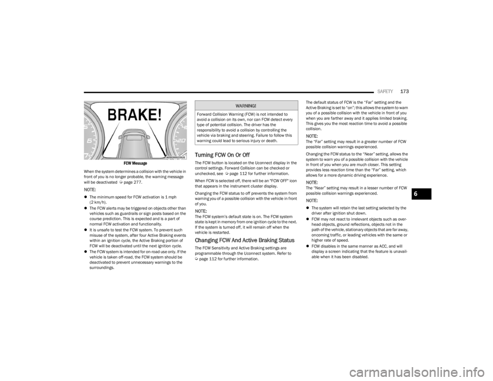
FCW Message
When the system determines a collision with the vehicle in
front of you is no longer probable, the warning message
will be deactivated
Úpage 277.
NOTE:
The minimum speed for FCW activation is 1 mph
(2 km/h).
The FCW alerts may be triggered on objects other than
vehicles such as guardrails or sign posts based on the
course prediction. This is expected and is a part of
normal FCW activation and functionality.
It is unsafe to test the FCW system. To prevent such
misuse of the system, after four Active Braking events
within an ignition cycle, the Active Braking portion of
FCW will be deactivated until the next ignition cycle.
The FCW system is intended for on-road use only. If the
vehicle is taken off-road, the FCW system should be
deactivated to prevent unnecessary warnings to the
surroundings.
Turning FCW On Or Off
The FCW button is located on the Uconnect display in the
control settings. Forward Collision can be checked or
unchecked, see
Úpage 112 for further information.
When FCW is selected off, there will be an "FCW OFF" icon
that appears in the instrument cluster display.
Changing the FCW status to off prevents the system from
warning you of a possible collision with the vehicle in front
of you.
NOTE:The FCW system’s default state is on. The FCW system
state is kept in memory from one ignition cycle to the next.
If the system is turned off, it will remain off when the
vehicle is restarted.
Changing FCW And Active Braking Status
The FCW Sensitivity and Active Braking settings are
programmable through the Uconnect system. Refer to
Úpage 112 for further information. The default status of FCW is the “Far” setting and the
Active Braking is set to “on”; this allows the system to warn
you of a possible collision with the vehicle in front of you
when you are farther away and it applies limited braking.
This gives you the most reaction time to avoid a possible
collision.
NOTE:The “Far” setting may result in a greater number of FCW
possible collision warnings experienced.
Changing the FCW status to the “Near” setting, allows the
system to warn you of a possible collision with the vehicle
in front of you when you are much closer. This setting
provides less reaction time than the “Far” setting, which
allows for a more dynamic driving experience.
NOTE:The “Near” setting may result in a lesser number of FCW
possible collision warnings experienced.
NOTE:
The system will retain the last setting selected by the
driver after ignition shut down.
FCW may not react to irrelevant objects such as over -
head objects, ground reflections, objects not in the
path of the vehicle, stationary objects that are far away,
oncoming traffic, or leading vehicles with the same or
higher rate of speed.
FCW disables in the same manner as ACC, and will
display a screen indicating that the feature is unavail -
able when it has been disabled.
WARNING!
Forward Collision Warning (FCW) is not intended to
avoid a collision on its own, nor can FCW detect every
type of potential collision. The driver has the
responsibility to avoid a collision by controlling the
vehicle via braking and steering. Failure to follow this
warning could lead to serious injury or death.
6
23_LD_OM_EN_USC_t.book Page 173
Page 178 of 292

176SAFETY
NOTE:When filling warm tires, the tire pressure may need to be
increased up to an additional 4 psi (28 kPa) above the
recommended cold placard pressure in order to turn the
TPMS Warning Light off.
Low Tire Pressure Monitoring System Display
Service Tire Pressure System Warning
If a system fault is detected, the Tire Pressure Monitoring
System (TPMS) Warning Light will flash on and off for 75
seconds and then remain on solid. The system fault will
also sound a chime. In addition, the instrument cluster will
display a "Service Tire Pressure System" message for a
minimum of five seconds and then display dashes (- -) in
place of the pressure value to indicate which sensor is not
being received.
If the ignition switch is cycled, this sequence will repeat,
providing the system fault still exists. If the system fault no
longer exists, the TPMS Warning Light will no longer flash,
and the "Service Tire Pressure System" message will no longer display, and a pressure value will display in place of
the dashes. A system fault can occur due to any of the
following:
Signal interference due to electronic devices or driving
next to facilities emitting the same radio frequencies
as the TPMS sensors.
Accumulation of snow or ice around the wheels or
wheel housings.
Using tire chains on the vehicle.
Using wheels/tires not equipped with TPMS sensors.
Vehicles With Compact Spare
1. The compact spare tire or non-matching full size does not have a Tire Pressure Monitoring System
sensor. Therefore, the TPMS will not monitor the
pressure in the compact or non-matching full size
spare tire.
2. If you install the compact or non-matching full size spare tire in place of a road tire that has a pressure
below the low-pressure warning limit, upon the next
ignition key cycle, the TPMS Warning Light will remain
on and a chime will sound. In addition, the graphic in
the instrument cluster will still display a different
color pressure value and an "Inflate to XX" message.
3. After driving the vehicle for up to 20 minutes above 15 mph (24 km/h), the TPMS Warning Light will flash
on and off for 75 seconds and then remain on solid.
In addition, the instrument cluster will display a
“Service Tire Pressure System” message for five
seconds and then display dashes (- -) in place of the
pressure value. 4. For each subsequent ignition key cycle, a chime will
sound, the TPMS Warning Light will flash on and off
for 75 seconds and then remain on solid, and the
instrument cluster will display a “Service Tire
Pressure System” message for five seconds and then
display dashes (- -) in place of the pressure value.
5. Once you repair or replace the original road tire and reinstall it on the vehicle in place of the compact
spare or non-matching full size, the TPMS will update
automatically. In addition, the TPMS Warning Light
will turn off and the graphic in the instrument cluster
will display a new pressure value instead of dashes
(- -), as long as no tire pressure is below the
low-pressure warning limit in any of the four active
road tires. The vehicle may need to be driven for up to
20 minutes above 15 mph (24 km/h) in order for the TPMS to receive this information.
TPMS Deactivation — If Equipped
The Tire Pressure Monitoring System (TPMS) can be
deactivated if replacing all four wheel and tire assemblies
(road tires) with wheel and tire assemblies that do not
have TPMS sensors, such as when installing winter wheel
and tire assemblies on your vehicle.
To deactivate the TPMS, first replace all four wheel and
tire assemblies (road tires) with tires not equipped with
Tire Pressure Monitoring System (TPMS) sensors. Then,
drive the vehicle for 20 minutes above 15 mph (24 km/h).
The TPMS will chime, the TPMS Warning Light will flash on
and off for 75 seconds and then remain on. The
instrument cluster will display the “Service Tire Pressure
System” message and then display dashes (--) in place of
the pressure values.
23_LD_OM_EN_USC_t.book Page 176