2023 DODGE CHARGER instrument panel
[x] Cancel search: instrument panelPage 190 of 292
188SAFETY
The Side Air Bags and seat belt pretensioners will not
deploy in all rollover events. The rollover sensing system
determines if a rollover event may be in progress and
whether deployment is appropriate. In the event the
vehicle experiences a rollover or near rollover event, and
deployment is appropriate, the rollover sensing system will
also deploy the side air bags and seat belt pretensioners
on both sides of the vehicle.
The SABICs may help reduce the risk of partial or complete
ejection of vehicle occupants through side windows in
certain rollover or side impact events.
Air Bag System Components
NOTE:The Occupant Restraint Controller (ORC) monitors the
internal circuits and interconnecting wiring associated
with electrical Air Bag System Components listed below:
Occupant Restraint Controller (ORC)
Air Bag Warning Light
Steering Wheel and Column
Instrument Panel
Knee Impact Bolsters
Driver and Front Passenger Air Bags
Seat Belt Buckle Switch
Supplemental Side Air Bags
Supplemental Knee Air Bags
Front and Side Impact Sensors
Seat Belt Pretensioners
Seat Track Position Sensors
If A Deployment Occurs
The front air bags are designed to deflate immediately
after deployment.
NOTE:Front and/or side air bags will not deploy in all collisions.
This does not mean something is wrong with the air bag
system.
If you do have a collision which deploys the air bags, any
or all of the following may occur:
The air bag material may sometimes cause abrasions
and/or skin reddening to the occupants as the air bags
deploy and unfold. The abrasions are similar to friction
rope burns or those you might get sliding along a carpet
or gymnasium floor. They are not caused by contact
with chemicals. They are not permanent and normally
heal quickly. However, if you haven’t healed signifi -
cantly within a few days, or if you have any blistering,
see your doctor immediately.
As the air bags deflate, you may see some smoke-like
particles. The particles are a normal by-product of the
process that generates the non-toxic gas used for air
bag inflation. These airborne particles may irritate the
skin, eyes, nose, or throat. If you have skin or eye irrita -
tion, rinse the area with cool water. For nose or throat
irritation, move to fresh air. If the irritation continues,
see your doctor. If these particles settle on your
clothing, follow the garment manufacturer’s instruc -
tions for cleaning. Do not drive your vehicle after the air bags have deployed.
If you are involved in another collision, the air bags will not
be in place to protect you.
NOTE:
Air bag covers may not be obvious in the interior trim,
but they will open during air bag deployment.
After any collision, the vehicle should be taken to an
authorized dealer immediately.
Enhanced Accident Response System
In the event of an impact, if the communication network
remains intact, and the power remains intact, depending
on the nature of the event, the Occupant Restraint
Controller (ORC) will determine whether to have the
Enhanced Accident Response System perform the
following functions:
Cut off fuel to the engine (if equipped).
Cut off battery power to the electric motor (if equipped).
Flash hazard lights as long as the battery has power.
Turn on the interior lights, which remain on as long as
the battery has power or for 15 minutes from the inter -
vention of the Enhanced Accident Response System.
Unlock the power door locks.
WARNING!
Deployed air bags and seat belt pretensioners cannot
protect you in another collision. Have the air bags, seat
belt pretensioners, and the seat belt retractor
assemblies replaced by an authorized dealer
immediately. Also, have the Occupant Restraint
Controller System serviced as well.
23_LD_OM_EN_USC_t.book Page 188
Page 191 of 292
SAFETY189
(Continued)
Your vehicle may also be designed to perform any of these
other functions in response to the Enhanced Accident
Response System:
Turn off the Fuel Filter Heater, Turn off the HVAC Blower
Motor, Close the HVAC Circulation Door
Cut off battery power to the:
Engine
Electric Motor (if equipped)
Electric power steering
Brake booster
Electric park brake
Automatic transmission gear selector
Horn
Front wiper
NOTE:After an accident, remember to cycle the ignition to the
STOP (OFF/LOCK) position and remove the key from the
ignition switch to avoid draining the battery. Carefully
check the vehicle for fuel leaks in the engine compartment
and on the ground near the engine compartment and fuel
tank before resetting the system and starting the engine.
If there are no fuel leaks or damage to the vehicle elec -
trical devices (e.g. headlights) after an accident, reset the
system by following the procedure described below. If you
have any doubt, contact an authorized dealer.
Enhanced Accident Response System
Reset Procedure
In order to reset the Enhanced Accident Response System
functions after an event, the ignition switch must be
changed from ignition START or ON/RUN to ignition OFF.
Carefully check the vehicle for fuel leaks in the engine
compartment and on the ground near the engine
compartment and fuel tank before resetting the system
and starting the engine.
After an accident, if the vehicle will not start after
performing the reset procedure, the vehicle must be
towed to an authorized dealer to be inspected and to have
the Enhanced Accident Response System reset.
Maintaining Your Air Bag System Event Data Recorder (EDR)
This vehicle is equipped with an event data recorder
(EDR). The main purpose of an EDR is to record, in certain
crash or near crash-like situations, such as an air bag
deployment or hitting a road obstacle, data that will assist
in understanding how a vehicle’s systems performed. The
EDR is designed to record data related to vehicle
dynamics and safety systems for a short period of time,
typically 30 seconds or less. The EDR in this vehicle is
designed to record such data as:
How various systems in your vehicle were operating;
Whether or not the driver and passenger safety belts
were buckled/fastened;
How far (if at all) the driver was depressing the acceler -
ator and/or brake pedal; and,
How fast the vehicle was traveling.WARNING!
Modifications to any part of the air bag system could
cause it to fail when you need it. You could be injured
if the air bag system is not there to protect you. Do
not modify the components or wiring, including
adding any kind of badges or stickers to the steering
wheel hub trim cover or the upper passenger side of
the instrument panel. Do not modify the front fascia/
bumper, vehicle body structure, or add aftermarket
side steps or running boards.
It is dangerous to try to repair any part of the air bag
system yourself. Be sure to tell anyone who works on
your vehicle that it has an air bag system.
Do not attempt to modify any part of your air bag
system. The air bag may inflate accidentally or may
not function properly if modifications are made. Take
your vehicle to an authorized dealer for any air bag
system service. If your seat, including your trim cover
and cushion, needs to be serviced in any way
(including removal or loosening/tightening of seat
attachment bolts), take the vehicle to an authorized
dealer. Only manufacturer approved seat accesso -
ries may be used. If it is necessary to modify the air
bag system for persons with disabilities, contact an
authorized dealer.
WARNING!
6
23_LD_OM_EN_USC_t.book Page 189
Page 203 of 292

SAFETY201
PERIODIC SAFETY CHECKS YOU SHOULD
M
AKE OUTSIDE THE VEHICLE
Tires
Examine tires for excessive tread wear and uneven wear
patterns. Check for stones, nails, glass, or other objects
lodged in the tread or sidewall. Inspect the tread for cuts
and cracks. Inspect sidewalls for cuts, cracks, and bulges.
Check the lug nuts/bolt torque for tightness. Check the
tires (including spare) for proper cold inflation pressure.
Lights
Have someone observe the operation of brake lights and
exterior lights while you work the controls. Check turn
signal and high beam indicator lights on the instrument
panel.
Door Latches
Check for proper closing, latching, and locking.
Fluid Leaks
Check area under the vehicle after overnight parking for
fuel, coolant, oil, or other fluid leaks. Also, if gasoline
fumes are detected or if fuel or brake fluid leaks are
suspected, the cause should be located and corrected
immediately.
EXHAUST GAS
The best protection against carbon monoxide entry into
the vehicle body is a properly maintained engine exhaust
system. Whenever a change is noticed in the sound of the exhaust
system, when exhaust fumes can be detected inside the
vehicle, or when the underside or rear of the vehicle is
damaged, have an authorized dealer inspect the complete
exhaust system and adjacent body areas for broken,
damaged, deteriorated, or mispositioned parts. Open
seams or loose connections could permit exhaust fumes
to seep into the passenger compartment. In addition,
inspect the exhaust system each time the vehicle is raised
for lubrication or oil change. Replace as required.
CARBON MONOXIDE WARNINGS
It is recommended to only use mild soap and water
to clean your floor mats. After cleaning, always check
your floor mat has been properly installed and is
secured to your vehicle using the floor mat fasteners
by lightly pulling mat.
WARNING!
WARNING!
Exhaust gases can injure or kill. They contain carbon
monoxide (CO), which is colorless and odorless.
Breathing it can make you unconscious and can
eventually poison you. To avoid breathing (CO), follow
these safety tips:
Do not run the engine in a closed garage or in
confined areas any longer than needed to move your
vehicle in or out of the area.
If you are required to drive with the trunk/liftgate/
rear doors open, make sure that all windows are
closed and the climate control BLOWER switch is set
at high speed. DO NOT use the recirculation mode.
If it is necessary to sit in a parked vehicle with the
engine running, adjust your heating or cooling
controls to force outside air into the vehicle. Set the
blower at high speed.
WARNING!
Carbon monoxide (CO) in exhaust gases is deadly.
Follow the precautions below to prevent carbon
monoxide poisoning:
Do not inhale exhaust gases. They contain carbon
monoxide, a colorless and odorless gas, which can
kill. Never run the engine in a closed area, such as a
garage, and never sit in a parked vehicle with the
engine running for an extended period. If the vehicle
is stopped in an open area with the engine running
for more than a short period, adjust the ventilation
system to force fresh, outside air into the vehicle.
Guard against carbon monoxide with proper mainte -
nance. Have the exhaust system inspected every
time the vehicle is raised. Have any abnormal condi -
tions repaired promptly. Until repaired, drive with all
side windows fully open.
6
23_LD_OM_EN_USC_t.book Page 201
Page 206 of 292

204IN CASE OF EMERGENCY
SOS Call System Limitations
Vehicles sold in Mexico DO NOT have SOS Call system
capabilities.
SOS or other emergency line operators in Mexico may not
answer or respond to SOS system calls. If the SOS Call system detects a malfunction, any of the
following may occur at the time the malfunction is
detected, and at the beginning of each ignition cycle:
The Rearview Mirror light located between the ASSIST
and SOS buttons will continuously illuminate red.
The Device Screen will display the following message
“Vehicle device requires service. Please contact an
authorized dealer”.
An In-Vehicle Audio message will state “Vehicle device
requires service. Please contact an authorized dealer”. Even if the SOS Call system is fully functional, factors
beyond FCA US LLC’s control may prevent or stop the SOS
Call system operation. These include, but are not limited
to, the following factors:
The ignition is in the OFF position.
The vehicle’s electrical systems are not intact.
The SOS Call system software and/or hardware are
damaged during a crash.
The vehicle battery loses power or becomes
disconnected during a vehicle crash.
LTE (voice/data) or 4G (data) network and/or Global
Positioning Satellite signals are unavailable or
obstructed.
Equipment malfunction at the SOS operator facility.
Operator error by the SOS operator.
LTE (voice/data) or 4G (data) network congestion.
Weather.
Buildings, structures, geographic terrain, or tunnels.
The SOS Call system is embedded into the vehicle’s
electrical system. Do not add aftermarket electrical
equipment to the vehicle’s electrical system. This
may prevent your vehicle from sending a signal to
initiate an emergency call. To avoid interference that
can cause the SOS Call system to fail, never add
aftermarket equipment (e.g., two-way mobile radio,
CB radio, data recorder, etc.) to your vehicle’s elec -
trical system or modify the antennas on your vehicle.
IF YOUR VEHICLE LOSES BATTERY POWER FOR ANY
REASON (INCLUDING DURING OR AFTER AN ACCI -
DENT), THE UCONNECT FEATURES, APPS AND
SERVICES, AMONG OTHERS, WILL NOT OPERATE.
Modifications to any part of the SOS Call system
could cause the air bag system to fail when you need
it. You could be injured if the air bag system is not
there to help protect you.
WARNING!
WARNING!
Ignoring the Rearview Mirror light could mean you
will not have SOS Call services. If the Rearview Mirror
light is illuminated, have an authorized dealer
service the SOS Call system immediately.
The Occupant Restraint Control module turns on the
air bag Warning Light on the instrument panel if a
malfunction in any part of the system is detected. If
the Air Bag Warning Light is illuminated, have an
authorized dealer service the Occupant Restraint
Control system immediately.
WARNING!
ALWAYS obey traffic laws and pay attention to the road.
ALWAYS drive safely with your hands on the steering
wheel. You have full responsibility and assume all risks
related to the use of the Uconnect and SiriusXM
Guardian™ features and applications in this vehicle.
Only use Uconnect features and SiriusXM Guardian™
services when it is safe to do so. Failure to do so may
result in an accident involving serious injury or death.
23_LD_OM_EN_USC_t.book Page 204
Page 214 of 292
212IN CASE OF EMERGENCY
3. The Sealant Bottle may be empty due to previous use.
Call for assistance.
NOTE:If the Mode Select Knob is on Air Mode and the pump is
operating, air will dispense from the Air Pump Hose only,
not the Sealant Hose .
If the sealant (white fluid) does flow through the Sealant
Hose:
1. Continue to operate the pump until sealant is no longer flowing through the hose (typically takes
30 - 70 seconds). As the sealant flows through the
Sealant Hose, the Pressure Gauge can read as high
as 70 psi (4.8 Bar). The Pressure Gauge will
decrease quickly from approximately 70 psi
(4.8 Bar) to the actual tire pressure when the
Sealant Bottle is empty.
2. The pump will start to inject air into the tire immediately after the Sealant Bottle is empty.
Continue to operate the pump and inflate the tire to
the pressure indicated on the tire pressure label on
the driver-side latch pillar (recommended pressure).
Check the tire pressure by looking at the Pressure
Gauge. If the tire does not inflate to at least 26 psi (1.8 Bar)
pressure within 15 minutes:
The tire is too badly damaged. Do not attempt to drive
the vehicle further. Call for assistance.NOTE:If the tire becomes overinflated, push the Deflation Button
to reduce the tire pressure to the recommended inflation
pressure before continuing.
If the tire inflates to the recommended pressure or is at
least 26 psi (1.8 Bar) pressure within 15 minutes:
1. Push the Power Button to turn off the Tire Service
Kit.
2. Remove the Speed Limit sticker from the top of the Sealant Bottle and place the sticker on the
instrument panel.
3. Immediately disconnect the Sealant Hose from the valve stem, reinstall the cap on the fitting at the end
of the hose, and place the Tire Service Kit in the
vehicle storage location.
(D) Drive Vehicle:
Immediately after injecting sealant and inflating the tire,
drive the vehicle 5 miles (8 km) or 10 minutes to ensure
distribution of the Tire Service Kit Sealant within the tire.
Do not exceed 50 mph (80 km/h).
(E) After Driving:
Pull over to a safe location before continuing Úpage 211.
1. Push in the Mode Select Knob and turn to the Air Mode position.
2. Uncoil the power plug and insert the plug into the vehicle's 12 Volt power outlet.
3. Uncoil the Air Pump Hose (black in color) and screw the fitting at the end of hose (8) onto the valve stem.
4. Check the pressure in the tire by reading the Pressure Gauge.
If tire pressure is less than 19 psi (1.3 Bar):
The tire is too badly damaged. Do not attempt to drive the
vehicle further. Call for assistance.
CAUTION!
The metal end fitting from Power Plug may get hot
after use, so it should be handled carefully.
Failure to reinstall the cap on the fitting at the end of
the Sealant Hose can result in sealant contacting
your skin, clothing, and the vehicle’s interior. It can
also result in sealant contacting internal Tire Service
Kit components which may cause permanent
damage to the kit.
WARNING!
Tire Service Kit is not a permanent flat tire repair. Have
the tire inspected and repaired or replaced after using
Tire Service Kit. Do not exceed 50 mph (80 km/h) until
the tire is repaired or replaced. Failure to follow this
warning can result in injuries that are serious or fatal to
you, your passengers, and others around you.
23_LD_OM_EN_USC_t.book Page 212
Page 215 of 292
IN CASE OF EMERGENCY213
If the tire pressure is 19 psi (1.3 Bar) or higher:
1. Push the Power Button to turn on Tire Service Kit
and inflate the tire to the pressure indicated on the
tire and loading information label on the driver-side
door opening.
NOTE:If the tire becomes overinflated, push the Deflation Button
to reduce the tire pressure to the recommended inflation
pressure before continuing.
2. Disconnect the Tire Service Kit from the valve stem, reinstall the cap on the valve stem and unplug from
12 Volt outlet.
3. Place the Tire Service Kit in its proper storage area in the vehicle.
4. Have the tire inspected and repaired or replaced at the earliest opportunity at an authorized dealer or tire
service center.
5. Remove the Speed Limit sticker from the instrument panel after the tire has been repaired.
6. Replace the Sealant Bottle and Sealant Hose assembly at an authorized dealer as soon as
possible.
NOTE:When having the tire serviced, advise the authorized
dealer or service center that the tire has been sealed
using the Tire Service Kit.
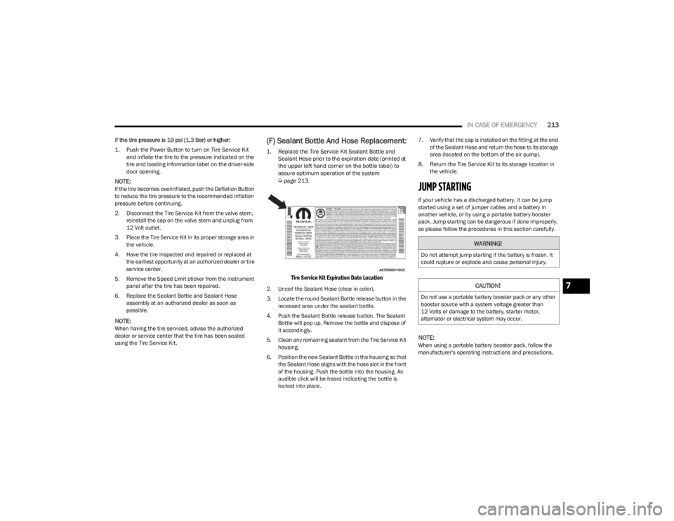
(F) Sealant Bottle And Hose Replacement:
1. Replace the Tire Service Kit Sealant Bottle and Sealant Hose prior to the expiration date (printed at
the upper left hand corner on the bottle label) to
assure optimum operation of the system
Ú
page 213.
Tire Service Kit Expiration Date Location
2. Uncoil the Sealant Hose (clear in color).
3. Locate the round Sealant Bottle release button in the
recessed area under the sealant bottle.
4. Push the Sealant Bottle release button. The Sealant Bottle will pop up. Remove the bottle and dispose of
it accordingly.
5. Clean any remaining sealant from the Tire Service Kit housing.
6. Position the new Sealant Bottle in the housing so that the Sealant Hose aligns with the hose slot in the front
of the housing. Push the bottle into the housing. An
audible click will be heard indicating the bottle is
locked into place. 7. Verify that the cap is installed on the fitting at the end
of the Sealant Hose and return the hose to its storage
area (located on the bottom of the air pump).
8. Return the Tire Service Kit to its storage location in the vehicle.
JUMP STARTING
If your vehicle has a discharged battery, it can be jump
started using a set of jumper cables and a battery in
another vehicle, or by using a portable battery booster
pack. Jump starting can be dangerous if done improperly,
so please follow the procedures in this section carefully.
NOTE:When using a portable battery booster pack, follow the
manufacturer's operating instructions and precautions.
WARNING!
Do not attempt jump starting if the battery is frozen. It
could rupture or explode and cause personal injury.
CAUTION!
Do not use a portable battery booster pack or any other
booster source with a system voltage greater than
12 Volts or damage to the battery, starter motor,
alternator or electrical system may occur.
7
23_LD_OM_EN_USC_t.book Page 213
Page 269 of 292

267
TECHNICAL SPECIFICATIONS
VEHICLE IDENTIFICATION NUMBER (VIN)
The VIN is on the left front corner of the instrument panel.
The VIN is visible from outside of the vehicle through the
windshield.
Windshield VIN Location
NOTE:
It is illegal to remove or alter the VIN.
BRAKE SYSTEM
Your vehicle is equipped with dual hydraulic brake
systems. If either of the two hydraulic systems lose normal
capability, the remaining system will still function. There
will be some loss of overall braking effectiveness. This
may be evident by increased pedal travel during
application, greater pedal force required to slow or stop,
and potential activation of the Brake Warning Light.
In the event power assist is lost for any reason (for
example, repeated brake applications with the engine off),
the brakes will still function. The effort required to brake
the vehicle will be much greater than that required with
the power system operating.
WHEEL AND TIRE TORQUE SPECIFICATIONS
Proper lug nut/bolt torque is very important to ensure that
the wheel is properly mounted to the vehicle. Any time a
wheel has been removed and reinstalled on the vehicle,
the lug nuts/bolts should be torqued using a properly
calibrated torque wrench using a six-sided (hex)
deep wall socket.
TORQUE SPECIFICATIONS
**Use only authorized dealer recommended lug
nuts/bolts and clean or remove any dirt or oil before
tightening.
Inspect the wheel mounting surface prior to mounting the
tire and remove any corrosion or loose particles.
Wheel Mounting Surface
Lug Nut/Bolt Torque **Lug Nut/Bolt
Size Lug Nut/Bolt
Socket Size
130 ft-lb
(176 N·m) M14 x 1.50 22 mm
9
23_LD_OM_EN_USC_t.book Page 267
Page 279 of 292
CUSTOMER ASSISTANCE277
Diagnostic Procedure Manuals
Diagnostic Procedure Manuals are filled with diagrams,
charts and detailed illustrations. These manuals make it
easy to find and fix problems on computer-controlled
vehicle systems and features. They show exactly how to
find and correct problems, using step-by-step
troubleshooting and drivability procedures, proven
diagnostic tests and a complete list of all tools and
equipment.
To order a hard copy of your Service or Diagnostic
Procedure manuals, visit:
www.techauthority.com (US and Canada).
Owner's Manuals
These Owner's Manuals have been prepared with the
assistance of service and engineering specialists to
acquaint you with specific FCA vehicles.
To access your Owner's Information online, visit
www.mopar.com/om (US) or www.owners.mopar.ca
(Canada).
Or
Call Tech Authority toll free at:
1-800-890-4038 (US)
Owner's Manuals, Radio Manuals and Warranty
Information Books can be ordered through Archway at:
1-800-387-1143 (Canada)CHANGE OF OWNERSHIP OR ADDRESS
*If you have purchased this vehicle used or have changed
your address, please provide the following information
and mail to:
FCA US LLC
P.O. Box 21–8008
Auburn Hills, MI 48321–8004
Make sure to include the following:
Date of Sale (mm/dd/yy)
Vehicle Indentification Number (17 Character ID
located on top left of the instrument panel)
Exact Odometer Reading
First and Last Name
Phone Number
Street Address, City, State and Zip Code
Email Address
*Applies to US residents only.
GENERAL INFORMATION
The following regulatory statement applies to all Radio
Frequency (RF) devices equipped in this vehicle:
This device complies with Part 15 of the FCC Rules and
with Innovation, Science and Economic Development
Canada license-exempt RSS standard(s). Operation is
subject to the following two conditions:
1. This device may not cause harmful interference, and
2. This device must accept any interference received, including interference that may cause undesired
operation.
Le présent appareil est conforme aux CNR d`Innovation,
Science and Economic Development applicables aux
appareils radio exempts de licence. L'exploitation est
autorisée aux deux conditions suivantes:
1. l'appareil ne doit pas produire de brouillage, et
2. l'utilisateur de l'appareil doit accepter tout brouillage radioélectrique subi, même si le brouillage est
susceptible d'en compromettre le fonctionnement.
La operación de este equipo está sujeta a las siguientes
dos condiciones:
1. es posible que este equipo o dispositivo no cause interferencia perjudicial y
2. este equipo o dispositivo debe aceptar cualquier interferencia, incluyendo la que pueda causar su
operación no deseada.
NOTE:Changes or modifications not expressly approved by the
party responsible for compliance could void the user’s
authority to operate the equipment.
10
23_LD_OM_EN_USC_t.book Page 277