2023 DODGE CHARGER clutch
[x] Cancel search: clutchPage 81 of 292

STARTING AND OPERATING79
(Continued)
ENGINE BREAK-IN RECOMMENDATIONS —
3.6L & 5.7L
A long break-in period is not required for the drivetrain
(engine, transmission, clutch, and rear axle) in your new
vehicle.
Drive moderately during the first 300 miles (500 km).
After the initial 60 miles (100 km), speeds up to 50 or
55 mph (80 or 90 km/h) are desirable.
While cruising, brief full-throttle acceleration within the
limits of local traffic laws contributes to a good break-in.
However, wide-open throttle acceleration in low gear can
be detrimental and should be avoided.
The engine oil, transmission fluid, and axle lubricant
installed at the factory is high-quality and
energy-conserving. Oil, fluid, and lubricant changes should
be consistent with anticipated climate and conditions
under which vehicle operations will occur. For the
recommended viscosity and quality grades
Úpage 271.
NOTE:A new engine may consume some oil during its first few
thousand miles (kilometers) of operation. This should be
considered a normal part of the break-in and not inter -
preted as an indication of difficulty. Please check your oil
level with the engine oil indicator often during the break in
period. Add oil as required.
PARKING BRAKE
Before leaving the vehicle, make sure that the parking
brake is fully applied and place the gear selector in the
PARK position.
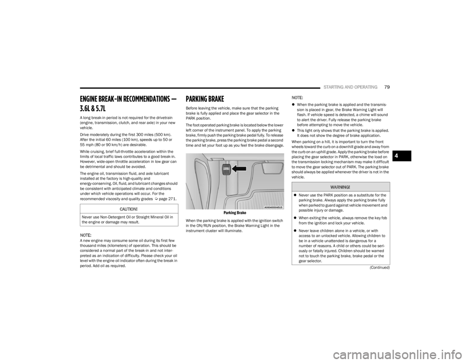
The foot operated parking brake is located below the lower
left corner of the instrument panel. To apply the parking
brake, firmly push the parking brake pedal fully. To release
the parking brake, press the parking brake pedal a second
time and let your foot up as you feel the brake disengage.
Parking Brake
When the parking brake is applied with the ignition switch
in the ON/RUN position, the Brake Warning Light in the
instrument cluster will illuminate.
NOTE:
When the parking brake is applied and the transmis -
sion is placed in gear, the Brake Warning Light will
flash. If vehicle speed is detected, a chime will sound
to alert the driver. Fully release the parking brake
before attempting to move the vehicle.
This light only shows that the parking brake is applied.
It does not show the degree of brake application.
When parking on a hill, it is important to turn the front
wheels toward the curb on a downhill grade and away from
the curb on an uphill grade. Apply the parking brake before
placing the gear selector in PARK, otherwise the load on
the transmission locking mechanism may make it difficult
to move the gear selector out of PARK. The parking brake
should always be applied whenever the driver is not in the
vehicle.
CAUTION!
Never use Non-Detergent Oil or Straight Mineral Oil in
the engine or damage may result.
WARNING!
Never use the PARK position as a substitute for the
parking brake. Always apply the parking brake fully
when parked to guard against vehicle movement and
possible injury or damage.
When exiting the vehicle, always remove the key fob
from the ignition and lock your vehicle.
Never leave children alone in a vehicle, or with
access to an unlocked vehicle. Allowing children to
be in a vehicle unattended is dangerous for a
number of reasons. A child or others could be seri -
ously or fatally injured. Children should be warned
not to touch the parking brake, brake pedal or the
gear selector.
4
23_LD_OM_EN_USC_t.book Page 79
Page 170 of 292

168SAFETY
The following conditions must be met in order for HSA to
activate:
The feature must be enabled.
The vehicle must be stopped.
The parking brake must be off.
The driver door must be closed.
The vehicle must be on a sufficient grade.
The gear selection must match vehicle uphill direction
(i.e., vehicle facing uphill is in forward gear; vehicle
backing uphill is in REVERSE gear).
HSA will work in REVERSE gear and all forward gears.
The system will not activate if the transmission is in
PARK or NEUTRAL. For vehicles equipped with a
manual transmission, if the clutch is pressed, HSA will
remain active.Disabling And Enabling HSA
This feature can be turned on or turned off. To disable
HSA, see Úpage 112 for further information.
Towing With HSA
HSA will also provide assistance to mitigate roll back while
towing a trailer.
Rain Brake Support (RBS)
RBS may improve braking performance in wet conditions.
It will periodically apply a small amount of brake pressure
to remove any water buildup on the front brake rotors. It
functions when the windshield wipers are in LO or HI
speed. When RBS is active, there is no notification to the
driver and no driver interaction is required.
Ready Alert Braking (RAB)
RAB may reduce the time required to reach full braking
during emergency braking situations. It anticipates when
an emergency braking situation may occur by monitoring
how fast the throttle is released by the driver. The
Electronic Brake Controller (EBC) will prepare the brake
system for a panic stop.
Traction Control System (TCS)
The TCS monitors the amount of wheel spin of each of the
driven wheels. If wheel spin is detected, the TCS may apply
brake pressure to the spinning wheel(s) and/or reduce
engine power to provide enhanced acceleration and
stability. A feature of the TCS, Brake Limited Differential
(BLD) functions similarly to a limited slip differential and
controls the wheel spin across a driven axle. If one wheel
on a driven axle is spinning faster than the other, the
system will apply the brake of the spinning wheel. This will
allow more engine power to be applied to the wheel that is
not spinning. BLD may remain enabled even if TCS and
ESC are in reduced modes.WARNING!
There may be situations where the Hill Start Assist
(HSA) will not activate and slight rolling may occur, such
as on minor hills or with a loaded vehicle, or while
pulling a trailer. HSA is not a substitute for active driving
involvement. It is always the driver’s responsibility to be
attentive to distance to other vehicles, people, and
objects, and most importantly brake operation to
ensure safe operation of the vehicle under all road
conditions. Your complete attention is always required
while driving to maintain safe control of your vehicle.
Failure to follow these warnings can result in a collision
or serious personal injury.
WARNING!
If you use a trailer brake controller with your trailer,
the trailer brakes may be activated and deactivated
with the brake switch. If so, there may not be enough
brake pressure to hold both the vehicle and the
trailer on a hill when the brake pedal is released. In
order to avoid rolling down an incline while resuming
acceleration, manually activate the trailer brake or
apply more vehicle brake pressure prior to releasing
the brake pedal.
HSA is not a parking brake. Always apply the parking
brake fully when exiting your vehicle. Also, be certain
to place the transmission in PARK.
Failure to follow these warnings can result in a colli -
sion or serious personal injury.
23_LD_OM_EN_USC_t.book Page 168
Page 202 of 292

200SAFETY
(Continued)
(Continued)
If your vehicle is involved in a collision, or if you have
questions regarding the seat belt or retractor conditions,
take your vehicle to an authorized FCA dealer or
authorized FCA Certified Collision Care Program facility for
inspection.
Air Bag Warning Light
The Air Bag Warning Light will turn on for four to
eight seconds as a bulb check when the
ignition switch is first placed in the ON/RUN
position. If the light is either not on during
starting, stays on, or turns on while driving, have the
system inspected at an authorized dealer as soon as
possible. After the bulb check, this light will illuminate with
a single chime when a fault with the Air Bag System has
been detected. It will stay on until the fault is removed. If
the light comes on intermittently or remains on while
driving, have an authorized dealer service the vehicle
immediately
Úpage 177.
Defroster
Check operation by selecting the defrost mode and place
the blower control on high speed. You should be able to
feel the air directed against the windshield. See an
authorized dealer for service if your defroster is
inoperable.
Floor Mat Safety Information
Always use floor mats designed to fit your vehicle. Only use
a floor mat that does not interfere with the operation of the
accelerator, brake or clutch pedals. Only use a floor mat
that is securely attached using the floor mat fasteners so
it cannot slip out of position and interfere with the
accelerator, brake or clutch pedals or impair safe
operation of your vehicle in other ways.
WARNING!
An improperly attached, damaged, folded, or stacked
floor mat, or damaged floor mat fasteners may cause
your floor mat to interfere with the accelerator, brake, or
clutch pedals and cause a loss of vehicle control. To
prevent SERIOUS INJURY or DEATH:
ALWAYS securely attach your floor mat
using the floor mat fasteners. DO NOT
install your floor mat upside down or turn
your floor mat over. Lightly pull to confirm
mat is secured using the floor mat fasteners on a
regular basis.
ALWAYS REMOVE THE EXISTING FLOOR
MAT FROM THE VEHICLE before installing
any other floor mat. NEVER install or stack
an additional floor mat on top of an
existing floor mat.
ONLY install floor mats designed to fit your vehicle.
NEVER install a floor mat that cannot be properly
attached and secured to your vehicle. If a floor mat
needs to be replaced, only use a FCA approved floor
mat for the specific make, model, and year of your
vehicle.ONLY use the driver’s side floor mat on the driver’s
side floor area. To check for interference, with the
vehicle properly parked with the engine off, fully
depress the accelerator, the brake, and the clutch
pedal (if present) to check for interference. If your
floor mat interferes with the operation of any pedal,
or is not secure to the floor, remove the floor mat
from the vehicle and place the floor mat in your
trunk.
ONLY use the passenger’s side floor mat on the
passenger’s side floor area.
ALWAYS make sure objects cannot fall or slide into
the driver’s side floor area when the vehicle is
moving. Objects can become trapped under acceler -
ator, brake, or clutch pedals and could cause a loss
of vehicle control.
NEVER place any objects under the floor mat (e.g.,
towels, keys, etc.). These objects could change the
position of the floor mat and may cause interference
with the accelerator, brake, or clutch pedals.
If the vehicle carpet has been removed and
re-installed, always properly attach carpet to the floor
and check the floor mat fasteners are secure to the
vehicle carpet. Fully depress each pedal to check for
interference with the accelerator, brake, or clutch
pedals then re-install the floor mats.
WARNING!
23_LD_OM_EN_USC_t.book Page 200
Page 220 of 292

218IN CASE OF EMERGENCY
3. Pull up gently on the tether strap to confirm that the
lever is locked in its stowed position.
4. Tuck the tether strap into the base of the console. Reinstall the Manual Park Release cover and the
console storage bin.
When the lever is in the release position the access cover
cannot be reinstalled.
FREEING A STUCK VEHICLE
If your vehicle becomes stuck in mud, sand, or snow, it can
often be moved using a rocking motion. Turn the steering
wheel right and left to clear the area around the front
wheels. For vehicles with automatic transmission, push
and hold the lock button on the gear selector. Then shift
back and forth between DRIVE and REVERSE (with
automatic transmission) or FIRST gear and REVERSE
(with manual transmission), while gently pressing the
accelerator. Use the least amount of accelerator pedal
pressure that will maintain the rocking motion, without
spinning the wheels or racing the engine.NOTE:For vehicles with automatic transmission: Shifts between
DRIVE and REVERSE can only be achieved at wheel
speeds of 5 mph (8 km/h) or less. Whenever the trans -
mission remains in NEUTRAL for more than two seconds,
you must press the brake pedal to engage DRIVE or
REVERSE.
Push the ESC OFF button to place the Electronic Stability
Control (ESC) system in “Partial OFF” mode, before rocking
the vehicle
Úpage 166. Once the vehicle has been freed,
push the ESC OFF button again to restore “ESC On” mode.
CAUTION!
Racing the engine or spinning the wheels may lead to
transmission overheating and failure. Allow the engine
to idle with the transmission in NEUTRAL for at least
one minute after every five rocking-motion cycles. This
will minimize overheating and reduce the risk of clutch
or transmission failure during prolonged efforts to free
a stuck vehicle.
WARNING!
Fast spinning tires can be dangerous. Forces generated
by excessive wheel speeds may cause damage, or even
failure, of the axle and tires. A tire could explode and
injure someone. Do not spin your vehicle's wheels
faster than 30 mph (48 km/h) or for longer than 30
seconds continuously without stopping when you are
stuck and do not let anyone near a spinning wheel, no
matter what the speed.
CAUTION!
Racing the engine or spinning the wheels may lead to
transmission overheating and failure. Allow the
engine to idle with the transmission in NEUTRAL for
at least one minute after every five rocking-motion
cycles. This will minimize overheating and reduce the
risk of transmission failure during prolonged efforts
to free a stuck vehicle.
When “rocking” a stuck vehicle by shifting between
DRIVE and REVERSE, do not spin the wheels faster
than 15 mph (24 km/h), or drivetrain damage may
result.
Revving the engine or spinning the wheels too fast
may lead to transmission overheating and failure. It
can also damage the tires. Do not spin the wheels
above 30 mph (48 km/h) while in gear (no transmis -
sion shifting occurring).
23_LD_OM_EN_USC_t.book Page 218
Page 242 of 292

240SERVICING AND MAINTENANCE
F03 50 Amp Red –Electric Power Steering #1 *
F04 30 Amp Pink –Starter
F05 40 Amp Green –Anti-Lock Brake
F06 30 Amp Pink –Anti-Lock Brake
F07 20 Amp Blue –Police Ignition Run / ACC #1
F08 20 Amp Blue –Police Ignition Run / ACC # 2
F09 –20 Amp Yellow All-Wheel Drive Module *
F10 –10 Amp RedIntrusion MOD (300) * / Under Hood Lamp – Police
F11 –20 Amp Yellow Horns
F12 –10 Amp RedAir Conditioning Clutch
F13 ––Spare
F14 ––Spare
F15 ––Spare
F16 ––Spare
F18 50 Amp Red –Radiator Fan #2
F19 50 Amp Red –Electric Power Steering #2 *
F20 30 Amp Pink –Wiper Motor
F21 30 Amp Pink
–Headlamp Washers *
20 Amp Blue Police Bat Feed #2
F22 40 Amp Green
–LTR Cooling Pump (6.2L Eng)
20 Amp Blue Police Bat Feed # 3
F23 20 Amp Blue –Police Bat Feed # 1
Cavity Cartridge Fuse Mini-Fuse Description
* If Equipped
23_LD_OM_EN_USC_t.book Page 240
Page 243 of 292

SERVICING AND MAINTENANCE241
F24 20 Amp Blue –Police Ignition Run/ACC Feed # 3
F28 ––Spare
F29 –15 Amp Blue Auto Trans (Challenger / Police)
F30 ––Spare
F31 –25 Amp Clear Engine Module
F32 ––Spare
F33 ––Spare
F34 –25 Amp Clear ASD Feed #1
F35 –20 Amp Yellow ASD Feed #2
F36 –10 Amp RedAnti-Lock Brake Module / Steering Column Lock Module *
F37 –10 Amp RedEngine Controller
F38 –10 Amp RedAirbag Module
F39 –10 Amp RedA/C Clutch / EPS */ Vacuum Pump *
F48 –10 Amp RedAWD Module / Front Axle Disconnect *
F49 ––Spare
F50 ––Spare
F51 –20 Amp Yellow Vacuum Pump *
F52 –5 Amp TanAdaptive Cruise Control *
F53 ––Spare
Cavity Cartridge Fuse Mini-Fuse Description
* If Equipped
8
23_LD_OM_EN_USC_t.book Page 241