Page 169 of 292

NOTE:
For vehicles with multiple partial ESC modes, the push
and release of the button will toggle the ESC modes.
Multiple attempts may be required to return to
\"ESC O")
SAFETY167
(Continued)
NOTE:
For vehicles with multiple partial ESC modes, the push
and release of the button will toggle the ESC modes.
Multiple attempts may be required to return to
"ESC On" mode.
Trailer Sway Control (TSC) is disabled when the
ESC system is in the “Partial Off” mode.
If Equipped — "ESC Sport" and "ESC Track" are
ESC “Partial Off” mode(s).
“Full Off” – If Equipped
This mode is intended for off-highway or off-road use only
and should not be used on any public roadways. In this
mode, TCS and ESC features are turned off. To enter the
“Full Off” mode, push and hold the ESC OFF button for five
seconds while the vehicle is stopped with the engine
running. After five seconds, a chime will sound, the ESC
OFF Indicator Light will illuminate, and the ESC OFF
message will display in the instrument cluster. To turn ESC
on again, momentarily push the ESC OFF button.
ESC Activation/Malfunction Indicator Light
And ESC OFF Indicator Light
The ESC Activation/Malfunction Indicator Light
in the instrument cluster will come on when the
ignition is placed in the ON/RUN mode. It
should go out with the engine running. If the
ESC Activation/Malfunction Indicator Light comes on
continuously with the engine running, a malfunction has
been detected in the ESC system. If this light remains on
after several ignition cycles, and the vehicle has been
driven several miles (kilometers) at speeds greater than
30 mph (48 km/h), see an authorized dealer as soon as possible to have the problem diagnosed and corrected.
The ESC Activation/Malfunction Indicator Light (located in
the instrument cluster) starts to flash as soon as the tires
lose traction and the ESC system becomes active. The ESC
Activation/Malfunction Indicator Light also flashes when
TCS is active. If the ESC Activation/Malfunction Indicator Light begins to
flash during acceleration, ease up on the accelerator and
apply as little throttle as possible. Be sure to adapt your
speed and driving to the prevailing road conditions.
The ESC OFF Indicator Light indicates the
customer has elected to have the Electronic
Stability Control (ESC) in a reduced mode.
NOTE:
The ESC Activation/Malfunction Indicator Light and the
ESC OFF Indicator Light come on momentarily each
time the ignition is placed in the ON mode.
Each time the ignition is placed in the ON mode, the
ESC system will be on even if it was turned off previ -
ously.
The ESC system will make buzzing or clicking sounds
when it is active. This is normal; the sounds will stop
when ESC becomes inactive following the maneuver
that caused the ESC activation.
Hill Start Assist (HSA)
HSA is designed to mitigate roll back from a complete stop
while on an incline. If the driver releases the brake while
stopped on an incline, HSA will continue to hold the brake
pressure for a short period. If the driver does not apply the
throttle before this time expires, the system will release
brake pressure and the vehicle will roll down the hill as
normal.WARNING!
In the ESC “Full Off” mode, the engine torque reduc -
tion and stability features are disabled. Therefore,
enhanced vehicle stability offered by the ESC system
is unavailable. In an emergency evasive maneuver,
the ESC system will not engage to assist in main -
taining stability. ESC “Full Off” mode is intended for
off-highway or off-road use only.
The Electronic Stability Control (ESC) cannot prevent
the natural laws of physics from acting on the
vehicle, nor can it increase the traction afforded by
prevailing road conditions. ESC cannot prevent all
accidents, including those resulting from excessive
speed in turns, driving on very slippery surfaces, or
hydroplaning. ESC also cannot prevent collisions.
WARNING!
6
23_LD_OM_EN_USC_t.book Page 167
Page 170 of 292

168SAFETY
The following conditions must be met in order for HSA to
activate:
The feature must be enabled.
The vehicle must be stopped.
The parking brake must be off.
The driver door must be closed.
The vehicle must be on a sufficient grade.
The gear selection must match vehicle uphill direction
(i.e., vehicle facing uphill is in forward gear; vehicle
backing uphill is in REVERSE gear).
HSA will work in REVERSE gear and all forward gears.
The system will not activate if the transmission is in
PARK or NEUTRAL. For vehicles equipped with a
manual transmission, if the clutch is pressed, HSA will
remain active.Disabling And Enabling HSA
This feature can be turned on or turned off. To disable
HSA, see Úpage 112 for further information.
Towing With HSA
HSA will also provide assistance to mitigate roll back while
towing a trailer.
Rain Brake Support (RBS)
RBS may improve braking performance in wet conditions.
It will periodically apply a small amount of brake pressure
to remove any water buildup on the front brake rotors. It
functions when the windshield wipers are in LO or HI
speed. When RBS is active, there is no notification to the
driver and no driver interaction is required.
Ready Alert Braking (RAB)
RAB may reduce the time required to reach full braking
during emergency braking situations. It anticipates when
an emergency braking situation may occur by monitoring
how fast the throttle is released by the driver. The
Electronic Brake Controller (EBC) will prepare the brake
system for a panic stop.
Traction Control System (TCS)
The TCS monitors the amount of wheel spin of each of the
driven wheels. If wheel spin is detected, the TCS may apply
brake pressure to the spinning wheel(s) and/or reduce
engine power to provide enhanced acceleration and
stability. A feature of the TCS, Brake Limited Differential
(BLD) functions similarly to a limited slip differential and
controls the wheel spin across a driven axle. If one wheel
on a driven axle is spinning faster than the other, the
system will apply the brake of the spinning wheel. This will
allow more engine power to be applied to the wheel that is
not spinning. BLD may remain enabled even if TCS and
ESC are in reduced modes.WARNING!
There may be situations where the Hill Start Assist
(HSA) will not activate and slight rolling may occur, such
as on minor hills or with a loaded vehicle, or while
pulling a trailer. HSA is not a substitute for active driving
involvement. It is always the driver’s responsibility to be
attentive to distance to other vehicles, people, and
objects, and most importantly brake operation to
ensure safe operation of the vehicle under all road
conditions. Your complete attention is always required
while driving to maintain safe control of your vehicle.
Failure to follow these warnings can result in a collision
or serious personal injury.
WARNING!
If you use a trailer brake controller with your trailer,
the trailer brakes may be activated and deactivated
with the brake switch. If so, there may not be enough
brake pressure to hold both the vehicle and the
trailer on a hill when the brake pedal is released. In
order to avoid rolling down an incline while resuming
acceleration, manually activate the trailer brake or
apply more vehicle brake pressure prior to releasing
the brake pedal.
HSA is not a parking brake. Always apply the parking
brake fully when exiting your vehicle. Also, be certain
to place the transmission in PARK.
Failure to follow these warnings can result in a colli -
sion or serious personal injury.
23_LD_OM_EN_USC_t.book Page 168
Page 171 of 292
 —
I
F EQUIPPED
The BSM system uses two radar sensors, located inside
the rear fascia/bumper, to detect highway licensable
vehicles")
SAFETY169
AUXILIARY DRIVING SYSTEMS
BLIND SPOT MONITORING (BSM) —
I
F EQUIPPED
The BSM system uses two radar sensors, located inside
the rear fascia/bumper, to detect highway licensable
vehicles (automobiles, trucks, motorcycles, etc.) that
enter the blind spot zones from the rear/front/side of the
vehicle.
Rear Detection Zones
When the vehicle is started, the BSM Warning Light will
momentarily illuminate in both outside rearview mirrors to
let the driver know that the system is operational.
The BSM system sensors operate when the vehicle is in
any forward gear.
BSM Warning Light
The BSM detection zone covers approximately one lane
width on both sides of the vehicle 12 ft (3.8 m). The zone
length starts at the outside rearview mirror and extends
approximately 10 ft (3 m) beyond the rear fascia/bumper
of the vehicle. The BSM system monitors the detection
zones on both sides of the vehicle when the vehicle speed
reaches approximately 6 mph (10 km/h) or higher and will
alert the driver of vehicles in these areas.
NOTE:
The BSM system DOES NOT alert the driver about
rapidly approaching vehicles that are outside the
detection zones.
The BSM system detection zone DOES NOT change if
your vehicle is towing a trailer. Therefore, visually verify
the adjacent lane is clear for both your vehicle and
trailer before making a lane change. If the trailer or
other object (i.e., bicycle, sports equipment) extends
beyond the side of your vehicle, this may result in the
BSM Warning Light remaining illuminated the entire
time the vehicle is in a forward gear.
The Blind Spot Monitoring (BSM) system may experi -
ence drop outs (blinking on and off) of the side mirror
warning indicator lamps when a motorcycle or any
small object remains at the side of the vehicle for
extended periods of time (more than a couple of
seconds).
The area on the rear fascia/bumper where the radar
sensors are located must remain free of snow, ice, and
dirt/road contamination so that the BSM system can
function properly. Do not block the area of the rear fascia/
bumper where the radar sensors are located with foreign
objects (bumper stickers, bicycle racks, etc.).
6
23_LD_OM_EN_USC_t.book Page 169
Page 172 of 292

170SAFETY
The BSM system can become blocked if snow, ice, mud, or
other road contaminations accumulate on the rear fascia/
bumper where the radar sensors are located. The system
may also detect blockage if the vehicle is operated in
areas with extremely low radar returns such as a desert or
parallel to a large elevation drop. If a blockage is detected,
a “Blind Spot Temporarily Unavailable, Wipe Rear
Corners” message will display in the cluster, both mirror
lights will illuminate, and BSM and RCP alerts will not
occur. This is normal operation. The system will
automatically recover and resume function when the
condition clears. To minimize system blockage, do not
block the area of the rear fascia/bumper where the radar
sensors are located with foreign objects (bumper stickers,
bicycle racks, etc.) and keep it clear of road
contaminations.
Sensor Location
The BSM system notifies the driver of objects in the
detection zones by illuminating the BSM Warning Light
located in the outside mirrors in addition to sounding an
audible (chime) alert and reducing the radio volume,
Úpage 172 for further information.
The BSM system monitors the detection zone from three
different entry points (side, rear, front) while driving to see
if an alert is necessary. The BSM system will issue an alert
during these types of zone entries.
Entering From The Side
Vehicles that move into your adjacent lanes from either
side of the vehicle.
Side Monitoring
Entering From The Rear
Vehicles that come up from behind your vehicle on either
side and enter the rear detection zone with a relative
speed of less than 31 mph (50 km/h).
Rear Monitoring
Overtaking Traffic
If you pass another vehicle slowly (with a relative speed of
less than 15 mph (24 km/h)) and the vehicle remains in the blind spot for approximately 1.5 seconds, the warning
light will be illuminated. If the difference in speed between
the two vehicles is greater than 15 mph (24 km/h), the
warning light will not illuminate.
23_LD_OM_EN_USC_t.book Page 170
Page 173 of 292

SAFETY171
Overtaking/Approaching
The BSM system is designed not to issue an alert on
stationary objects such as guardrails, posts, walls, foliage,
berms, etc. However, occasionally the system may alert on
such objects. This is normal operation and your vehicle
does not require service.
Overtaking/Passing
The BSM system will not alert you of objects that are
traveling in the opposite direction of the vehicle in
adjacent lanes
Úpage 277.
Opposing Traffic
Rear Cross Path (RCP)
RCP is intended to aid the driver when backing out of
parking spaces where their vision of oncoming vehicles
may be blocked. Proceed slowly and cautiously out of the
parking space until the rear end of the vehicle is exposed.
The RCP system will then have a clear view of the cross
traffic and if an oncoming vehicle is detected, alert the
driver.
RCP Detection Zones
RCP monitors the rear detection zones on both sides of
the vehicle, for objects that are moving toward the side of
the vehicle with a minimum speed of approximately 3 mph
(5 km/h), to objects moving a maximum of approximately
20 mph (32 km/h), such as in parking lot situations.
WARNING!
The Blind Spot Monitoring system is only an aid to help
detect objects in the blind spot zones. The BSM system
is not designed to detect pedestrians, bicyclists, or
animals. Even if your vehicle is equipped with the BSM
system, always check your vehicle’s mirrors, glance
over your shoulder, and use your turn signal before
changing lanes. Failure to do so can result in serious
injury or death.
6
23_LD_OM_EN_USC_t.book Page 171
Page 174 of 292

172SAFETY
When RCP is on and the vehicle is in REVERSE, the driver
is alerted using both the visual and audible alarms,
including reducing the radio volume.
NOTE:In a parking lot situation, oncoming vehicles can be
blocked by vehicles parked on either side. If the sensors
are blocked by other structures or vehicles, the system will
not be able to alert the driver.
Blind Spot Modes
Blind Spot Alert Lights Only
Blind Spot has three selectable modes of operation that
are available in the Uconnect system.
When operating in Blind Spot Alert mode, the BSM system
will provide a visual alert in the appropriate side view
mirror based on a detected object. However, when the
system is operating in Rear Cross Path mode, the system
will respond with both visual and audible alerts when a
detected object is present. Whenever an audible alert is
requested, the radio volume is reduced so that the alert
can be better heard. Blind Spot Alert Lights/Chime
When operating in Blind Spot Alert Lights/Chime mode,
the BSM system will provide a visual alert in the
appropriate side view mirror based on a detected object.
If the turn signal is then activated, and it corresponds to
an alert present on that side of the vehicle, an audible
chime will also be sounded. Whenever a turn signal and
detected object are present on the same side at the same
time, both the visual and audio alerts will be issued. In
addition to the audible alert the radio (if on) volume will be
reduced so that the alert can be better heard.
When the system is in RCP, the system shall respond with
both visual and audible alerts when a detected object is
present. Whenever an audible alert is requested, the radio
volume is reduced so that the alert can be better heard.
Blind Spot Alert Off
When the BSM system is turned off there will be no visual
or audible alerts from either the BSM or RCP systems.
NOTE:The BSM system will store the current operating mode
when the vehicle is shut off. Each time the vehicle is
started the previously stored mode will be recalled and
used.
FORWARD COLLISION WARNING (FCW)
W
ITH MITIGATION OPERATION
FCW with Mitigation provides the driver with audible
warnings, visual warnings (within the instrument cluster
display), and may apply haptic warning in the form of a a
brake jerk, to warn the driver when it detects a potential
frontal collision. The warnings and limited braking are
intended to provide the driver with enough time to react,
avoid or mitigate the potential collision.
NOTE:FCW monitors the information from the forward looking
sensors, as well as the Electronic Stability Control (ESC)
system, to calculate the probability of a forward collision.
When the system determines that a forward collision is
probable, the driver will be provided with audible and
visual warnings and may provide a brake jerk warning.
If the driver does not take action based upon these
progressive warnings, then the system will provide a
limited level of active braking to help slow the vehicle and
mitigate the potential forward collision. If the driver reacts
to the warnings by braking and the system determines
that the driver intends to avoid the collision by braking but
has not applied sufficient brake force, the system will
compensate and provide additional brake force as
required. If a Forward Collision Warning with Mitigation
event begins at a speed below 20 mph (32 km/h), the
system may provide the maximum or partial braking to
mitigate the potential forward collision. If the Forward
Collision Warning with Mitigation event stops the vehicle
completely, the system will hold the vehicle at standstill for
two seconds and then release the brakes.
WARNING!
Rear Cross Path Detection (RCP) is not a back up aid
system. It is intended to be used to help a driver detect
an oncoming vehicle in a parking lot situation. Drivers
must be careful when backing up, even when using
RCP. Always check carefully behind your vehicle, look
behind you, and be sure to check for pedestrians,
animals, other vehicles, obstructions, and blind spots
before backing up. Failure to do so can result in serious
injury or death.
23_LD_OM_EN_USC_t.book Page 172
Page 175 of 292

SAFETY173
FCW Message
When the system determines a collision with the vehicle in
front of you is no longer probable, the warning message
will be deactivated
Úpage 277.
NOTE:
The minimum speed for FCW activation is 1 mph
(2 km/h).
The FCW alerts may be triggered on objects other than
vehicles such as guardrails or sign posts based on the
course prediction. This is expected and is a part of
normal FCW activation and functionality.
It is unsafe to test the FCW system. To prevent such
misuse of the system, after four Active Braking events
within an ignition cycle, the Active Braking portion of
FCW will be deactivated until the next ignition cycle.
The FCW system is intended for on-road use only. If the
vehicle is taken off-road, the FCW system should be
deactivated to prevent unnecessary warnings to the
surroundings.
Turning FCW On Or Off
The FCW button is located on the Uconnect display in the
control settings. Forward Collision can be checked or
unchecked, see
Úpage 112 for further information.
When FCW is selected off, there will be an "FCW OFF" icon
that appears in the instrument cluster display.
Changing the FCW status to off prevents the system from
warning you of a possible collision with the vehicle in front
of you.
NOTE:The FCW system’s default state is on. The FCW system
state is kept in memory from one ignition cycle to the next.
If the system is turned off, it will remain off when the
vehicle is restarted.
Changing FCW And Active Braking Status
The FCW Sensitivity and Active Braking settings are
programmable through the Uconnect system. Refer to
Úpage 112 for further information. The default status of FCW is the “Far” setting and the
Active Braking is set to “on”; this allows the system to warn
you of a possible collision with the vehicle in front of you
when you are farther away and it applies limited braking.
This gives you the most reaction time to avoid a possible
collision.
NOTE:The “Far” setting may result in a greater number of FCW
possible collision warnings experienced.
Changing the FCW status to the “Near” setting, allows the
system to warn you of a possible collision with the vehicle
in front of you when you are much closer. This setting
provides less reaction time than the “Far” setting, which
allows for a more dynamic driving experience.
NOTE:The “Near” setting may result in a lesser number of FCW
possible collision warnings experienced.
NOTE:
The system will retain the last setting selected by the
driver after ignition shut down.
FCW may not react to irrelevant objects such as over -
head objects, ground reflections, objects not in the
path of the vehicle, stationary objects that are far away,
oncoming traffic, or leading vehicles with the same or
higher rate of speed.
FCW disables in the same manner as ACC, and will
display a screen indicating that the feature is unavail -
able when it has been disabled.
WARNING!
Forward Collision Warning (FCW) is not intended to
avoid a collision on its own, nor can FCW detect every
type of potential collision. The driver has the
responsibility to avoid a collision by controlling the
vehicle via braking and steering. Failure to follow this
warning could lead to serious injury or death.
6
23_LD_OM_EN_USC_t.book Page 173
Page 176 of 292

FCW Limited Warning
If the instrument cluster display reads “ACC/FCW Limited
Functionality” or “ACC/FCW Limited Functionality Clean
Front Windshield” momentarily, th")
174SAFETY
(Continued)
FCW Limited Warning
If the instrument cluster display reads “ACC/FCW Limited
Functionality” or “ACC/FCW Limited Functionality Clean
Front Windshield” momentarily, there may be a condition
that limits FCW functionality. Although the vehicle is still
drivable under normal conditions, the active braking may
not be fully available. Once the condition that limited the
system performance is no longer present, the system will
return to its full performance state. If the problem persists,
see an authorized dealer.
Service FCW Warning
If the system turns off, and the instrument cluster display
reads:
ACC/FCW Unavailable Service Required
Cruise/FCW Unavailable Service Required
This indicates there is an internal system fault. Although
the vehicle is still drivable under normal conditions, have
the system checked by an authorized dealer.
TIRE PRESSURE MONITORING SYSTEM
(TPMS)
The Tire Pressure Monitoring System (TPMS) will warn the
driver of a low tire pressure based on the vehicle
recommended cold placard pressure.
The tire pressure will vary with temperature by about 1 psi
(7 kPa) for every 12°F (6.5°C). This means that when the
outside temperature decreases, the tire pressure will
decrease. Tire pressure should always be set based on
cold inflation tire pressure. This is defined as the tire pressure after the vehicle has
not been driven for at least three hours, or driven less than
1 mile (1.6 km) after a three hour period. The cold tire
inflation pressure must not exceed the maximum inflation
pressure molded into the tire sidewall. The tire pressure
will also increase as the vehicle is driven — this is normal
and there should be no adjustment for this increased
pressure.
See
Úpage 248 for information on how to properly inflate
the vehicle’s tires.
The TPMS will warn the driver of a low tire pressure if the
tire pressure falls below the low-pressure warning limit for
any reason, including low temperature effects and natural
pressure loss through the tire.
The TPMS will continue to warn the driver of low tire
pressure as long as the condition exists, and will not turn
off until the tire pressure is at or above the recommended
cold placard pressure. Once the low tire pressure warning
(TPMS Warning Light) illuminates, you must increase the
tire pressure to the recommended cold placard pressure
in order for the TPMS Warning Light to turn off. The system
will automatically update and the TPMS Warning Light will
turn off once the system receives the updated tire
pressures. The vehicle may need to be driven for up to
20 minutes above 15 mph (24 km/h) in order for the TPMS to receive this information.
NOTE:When filling warm tires, the tire pressure may need to be
increased up to an additional 4 psi (28 kPa) above the
recommended cold placard pressure in order to turn the
TPMS Warning Light off.
For example, your vehicle may have a recommended cold
(parked for more than three hours) placard pressure of
30 psi (207 kPa). If the ambient temperature is 68°F
(20°C) and the measured tire pressure is 27 psi
(186 kPa), a temperature drop to 20°F (-7°C) will
decrease the tire pressure to approximately 23 psi
(158 kPa). This tire pressure is sufficiently low enough to
turn on the TPMS Warning Light. Driving the vehicle may
cause the tire pressure to rise to approximately 27 psi
(186 kPa), but the TPMS Warning Light will still be on. In
this situation, the TPMS Warning Light will turn off only
after the tires are inflated to the vehicle’s recommended
cold placard pressure value.
CAUTION!
The TPMS has been optimized for the original equip -
ment tires and wheels. TPMS pressures and warning
have been established for the tire size equipped on
your vehicle. Undesirable system operation or sensor
damage may result when using replacement equip -
ment that is not of the same size, type, and/or style.
The TPMS sensor is not designed for use on after -
market wheels and may contribute to a poor overall
system performance or sensor damage. Customers
are encouraged to use Original Equipment Manufac -
turer (OEM) wheels to ensure proper TPMS feature
operation.
23_LD_OM_EN_USC_t.book Page 174
 1
1 2
2 3
3 4
4 5
5 6
6 7
7 8
8 9
9 10
10 11
11 12
12 13
13 14
14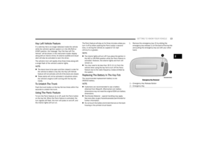 15
15 16
16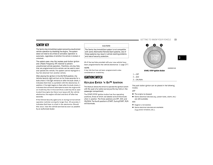 17
17 18
18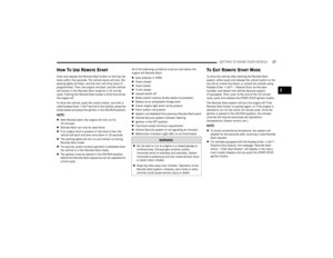 19
19 20
20 21
21 22
22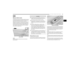 23
23 24
24 25
25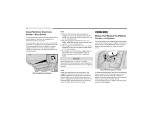 26
26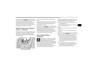 27
27 28
28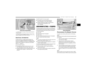 29
29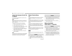 30
30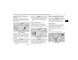 31
31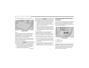 32
32 33
33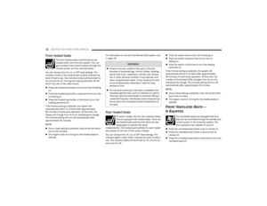 34
34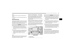 35
35 36
36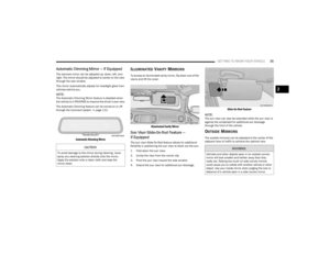 37
37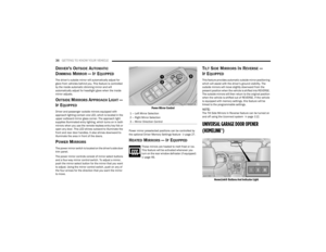 38
38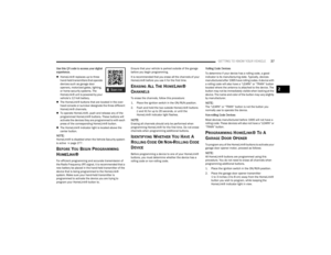 39
39 40
40 41
41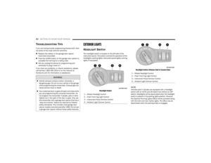 42
42 43
43 44
44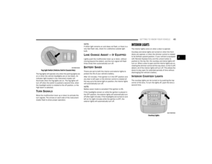 45
45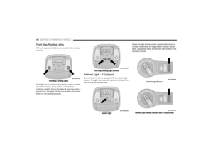 46
46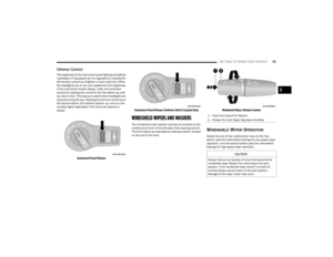 47
47 48
48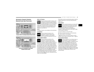 49
49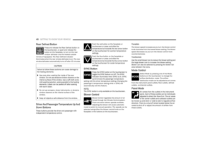 50
50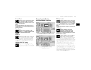 51
51 52
52 53
53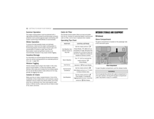 54
54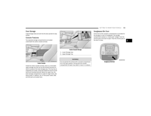 55
55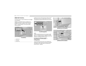 56
56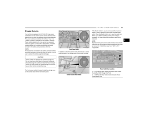 57
57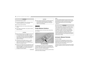 58
58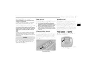 59
59 60
60 61
61 62
62 63
63 64
64 65
65 66
66 67
67 68
68 69
69 70
70 71
71 72
72 73
73 74
74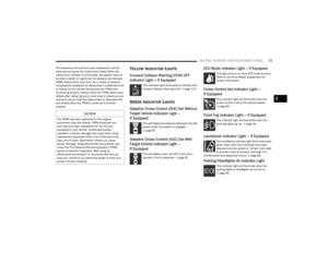 75
75 76
76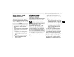 77
77 78
78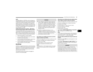 79
79 80
80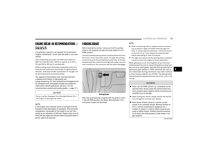 81
81 82
82 83
83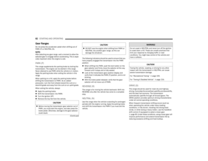 84
84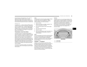 85
85 86
86 87
87 88
88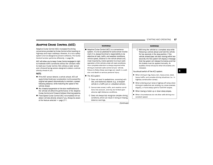 89
89 90
90 91
91 92
92 93
93 94
94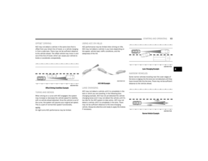 95
95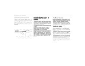 96
96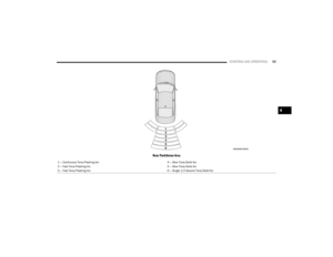 97
97 98
98 99
99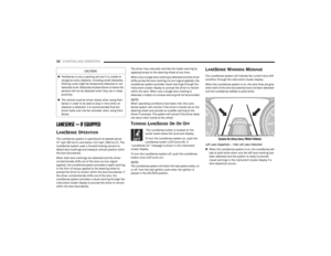 100
100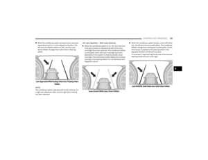 101
101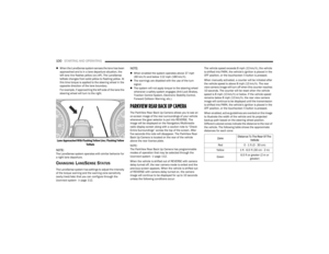 102
102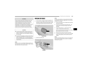 103
103 104
104 105
105 106
106 107
107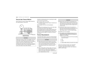 108
108 109
109 110
110 111
111 112
112 113
113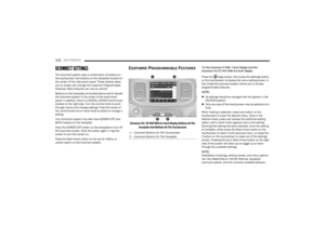 114
114 115
115 116
116 117
117 118
118 119
119 120
120 121
121 122
122 123
123 124
124 125
125 126
126 127
127 128
128 129
129 130
130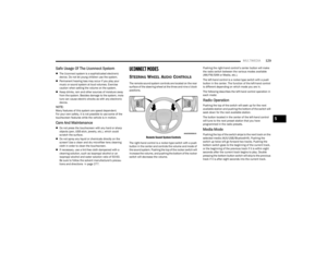 131
131 132
132 133
133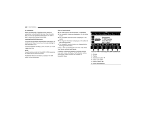 134
134 135
135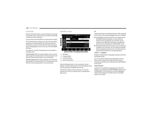 136
136 137
137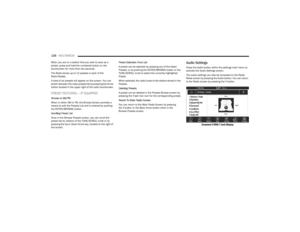 138
138 139
139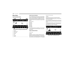 140
140 141
141 142
142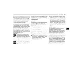 143
143 144
144 145
145 146
146 147
147 148
148 149
149 150
150 151
151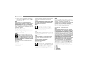 152
152 153
153 154
154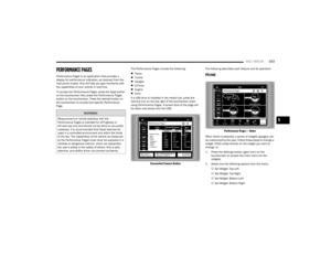 155
155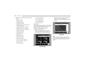 156
156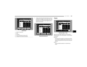 157
157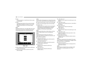 158
158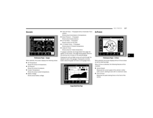 159
159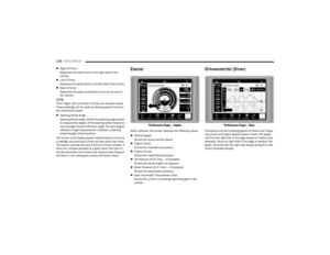 160
160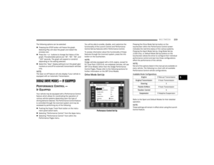 161
161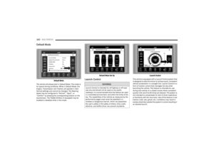 162
162 163
163 164
164 165
165 166
166 167
167 168
168 169
169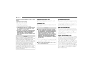 170
170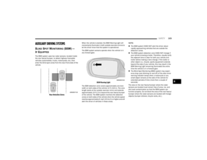 171
171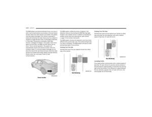 172
172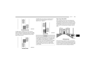 173
173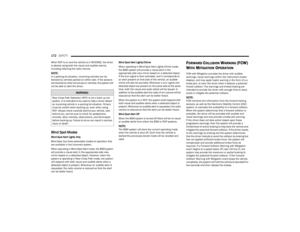 174
174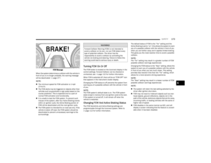 175
175 176
176 177
177 178
178 179
179 180
180 181
181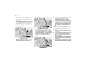 182
182 183
183 184
184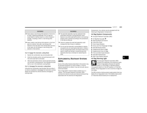 185
185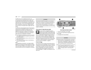 186
186 187
187 188
188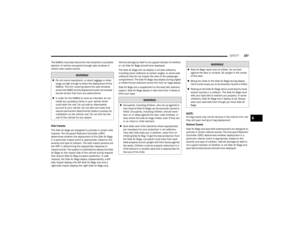 189
189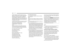 190
190 191
191 192
192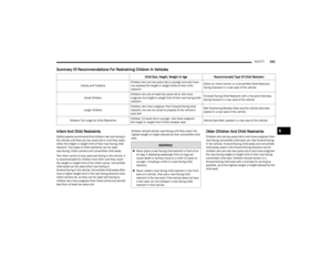 193
193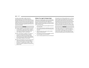 194
194 195
195 196
196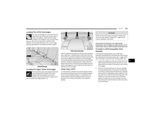 197
197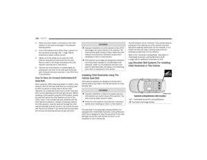 198
198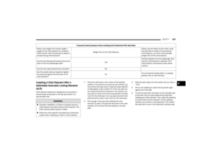 199
199 200
200 201
201 202
202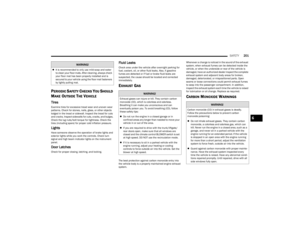 203
203 204
204 205
205 206
206 207
207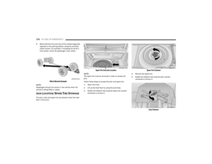 208
208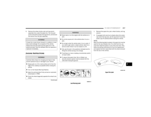 209
209 210
210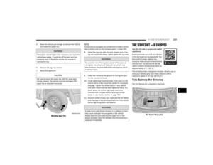 211
211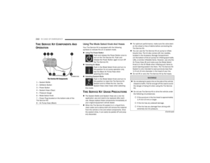 212
212 213
213 214
214 215
215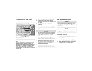 216
216 217
217 218
218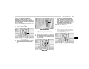 219
219 220
220 221
221 222
222 223
223 224
224 225
225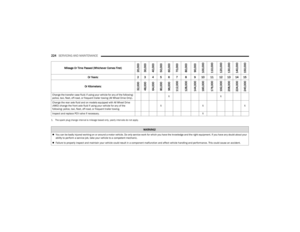 226
226 227
227 228
228 229
229 230
230 231
231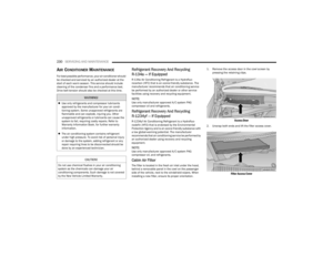 232
232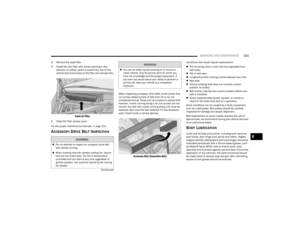 233
233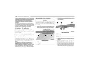 234
234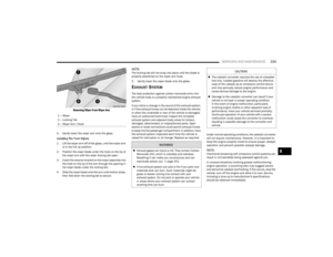 235
235 236
236 237
237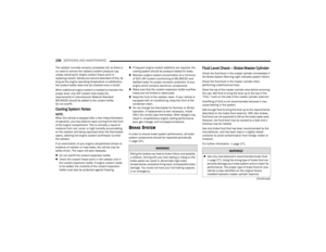 238
238 239
239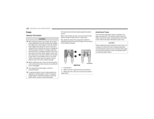 240
240 241
241 242
242 243
243 244
244 245
245 246
246 247
247 248
248 249
249 250
250 251
251 252
252 253
253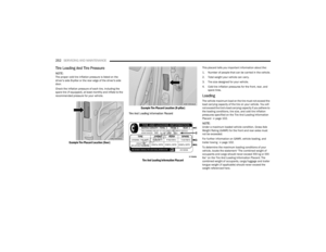 254
254 255
255 256
256 257
257 258
258 259
259 260
260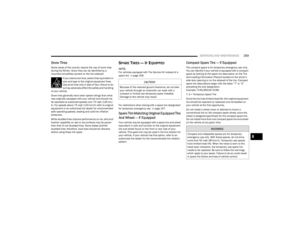 261
261 262
262 263
263 264
264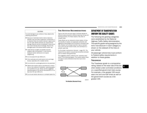 265
265 266
266 267
267 268
268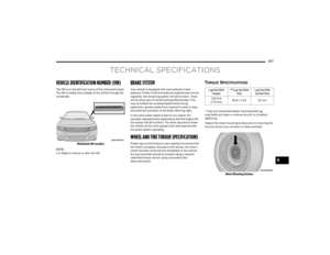 269
269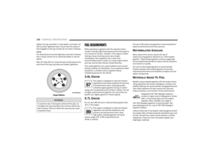 270
270 271
271 272
272 273
273 274
274 275
275 276
276 277
277 278
278 279
279 280
280 281
281 282
282 283
283 284
284 285
285 286
286 287
287 288
288 289
289 290
290 291
291