Page 65 of 136

Instrument and control functions
4-42
4
EAU39672
Rear view mirrorsThe rear view mirrors of this vehicle
can be folded forward or backward for
parking in narrow spaces. Fold the mir-
rors back to their original position be-
fore riding.
WARNING
EWA14372
Be sure to fold the rear view mirrors
back to their original position before
riding.
EAU66478
Adjusting the front forkNOTICE
ECA22472
Use extra care to avoid scratch-
ing the anodized finish when
making suspension adjust-
ments.
To avoid damaging the suspen-
sion’s internal mechanisms, do
not attempt to turn beyond the
maximum or minimum settings.YZF-R1
This model is equipped with adjustable
suspension. The spring preload, re-
bound damping force, and compres-
sion damping force of each leg can be
adjusted.
WARNING
EWA10181
Always adjust both fork legs equally,
otherwise poor handling and loss of
stability may result.Spring preload
Turn the adjusting nut in direction (a) to
increase the spring preload. Turn the adjusting nut in direction (b) to
decrease the spring preload.
To set the spring preload, turn the ad-
juster in direction (b) until it stops, and
then count the turns in direction (a).
1. Riding position
2. Parking position11
22
1. Spring preload adjusting nut
Spring preload setting:
Minimum (soft): 0 turn(s) in direction (a)
Standard: 6 turn(s) in direction (a)
Maximum (hard):
15 turn(s) in direction (a)
(b)
(a) 1
UB3LE1E0.book Page 42 Tuesday, August 10, 2021 2:28 PM
Page 66 of 136
, it may turn be-
yond the stated specifications,
however such adjustments are ineffec-
tive and m")
Instrument and control functions
4-43
4
TIPWhen turning the spring preload ad-
juster in direction (a), it may turn be-
yond the stated specifications,
however such adjustments are ineffec-
tive and may damage the suspension.Rebound damping force
Turn the adjusting bolt in direction (a)
to increase the rebound damping for-
ce.
Turn the adjusting bolt in direction (b)
to decrease the rebound damping for-
ce.
To set the rebound damping force, turn
the adjuster in direction (a) until it
stops, and then count the clicks in di-
rection (b).
TIPWhen turning the damping force
adjuster in direction (a), the 0 click
position and the 1 click position
may be the same.
When turning the damping force
adjuster in direction (b), it may
click beyond the stated specifica- tions, however such adjustments
are ineffective and may damage
the suspension.
Compression damping force
Turn the adjusting bolt in direction (a)
to increase the compression damping
force.
Turn the adjusting bolt in direction (b)
to decrease the compression damping
force.
To set the compression damping for-
ce, turn the adjuster in direction (a) until
it stops, and then count the clicks in di-
rection (b).
1. Rebound damping force adjusting boltRebound damping setting:
Minimum (soft):14 click(s) in direction (b)
Standard: 7 click(s) in direction (b)
Maximum (hard):
1 click(s) in direction (b)
(b)
(a) 1
1. Compression damping force adjusting bolt
(b)
(a)
1
UB3LE1E0.book Page 43 Tuesday, August 10, 2021 2:28 PM
Page 67 of 136
, the 0 click
position and the 1 click position
may be the same.
When turning the damping forc")
Instrument and control functions
4-44
4
TIPWhen turning the damping force
adjuster in direction (a), the 0 click
position and the 1 click position
may be the same.
When turning the damping force
adjuster in direction (b), it may
click beyond the stated specifica-
tions, however such adjustments
are ineffective and may damage
the suspension.YZF-R1M
This model is equipped with ÖHLINS
electronic racing suspension with gas
reservoir. The compression and re-
bound damping forces are electroni-
cally adjusted (see ERS on page 4-20).
The spring preload is manually adjust-
ed.
WARNING
EWA20900
The front fork legs contain highly
pressurized nitrogen gas. Read and
understand the following informa-
tion before handling the front fork
legs.
Do not subject the axle brackets
to open flame or other heat
source. This may cause the
units to explode due to exces-
sive gas pressure.
Do not attempt to open the gas
cylinder assemblies.
Do not deform or damage the
cylinders in any way. Cylinder
damage will result in poor
damping performance.
Do not dispose of a damaged or
worn-out front fork leg yourself.
Take the front fork leg to a
Yamaha dealer for disposal.Spring preload 1. Turn the vehicle off.
2. Slide the rubber cover back at each coupler. 3. Remove the coupler on each front
fork. NOTICE: To prevent dam-
aging the couplers, do not use
sharp tools or excessive force.
[ECA22770]
4. Turn the adjusting bolt in direction (a) to increase the spring preload.
Turn the adjusting bolt in direction
(b) to decrease the spring preload.
To set the spring preload, turn the
adjuster in direction (b) until it
stops, and then count the turns in
direction (a).
Compression damping setting:Minimum (soft):
23 click(s) in direction (b)
Standard:
17 click(s) in direction (b)
Maximum (hard): 1 click(s) in direction (b)
1. Rubber cover
2. Coupler
2
1
UB3LE1E0.book Page 44 Tuesday, August 10, 2021 2:28 PM
Page 68 of 136
, it may turn be-
yond the stated specifications,
however such adjustments are ineffec-
tive and m")
Instrument and control functions
4-45
4
TIPWhen turning the spring preload ad-
juster in direction (a), it may turn be-
yond the stated specifications,
however such adjustments are ineffec-
tive and may damage the suspension.5. Attach the coupler on each fork.
6. Slide the rubber cover to the orig-inal position.
EAU66499
Adjusting the shock absorber
assembly
WARNING
EWA10222
This shock absorber assembly con-
tains highly pressurized nitrogen
gas. Read and understand the fol-
lowing information before handling
the shock absorber assembly.
Do not tamper with or attempt
to open the cylinder assembly.
Do not subject the shock ab-
sorber assembly to an open
flame or other high heat source.
This may cause the unit to ex-
plode due to excessive gas
pressure.
Do not deform or damage the
cylinder in any way. Cylinder
damage will result in poor
damping performance.
Do not dispose of a damaged or
worn-out shock absorber as-
sembly yourself. Take the shock
absorber assembly to a Yamaha
dealer for any service.
YZF-R1
This model is equipped with adjustable
suspension. The spring preload, re-
bound damping force, fast compres-
sion damping force, and slow
compression damping force can be
adjusted.NOTICE
ECA10102
To avoid damaging the mechanism,
do not attempt to turn beyond the
maximum or minimum settings.Spring preload
1. Loosen the locknut.
2. Turn the adjusting nut in direction (a) to increase the spring preload.
Turn the adjusting nut in direction
(b) to decrease the spring preload.
The spring preload setting is de-
termined by measuring distance
A. The longer distance A is, the
higher the spring preload; the
shorter distance A is, the lower the
spring preload. Use the special wrench in-
cluded in the tool kit to make
the adjustment.
1. Spring preload adjusting boltSpring preload setting:
Minimum (soft):0 turn(s) in direction (a)
Standard: 3 turn(s) in direction (a)
Maximum (hard):
15 turn(s) in direction (a)
1
(a) (b)
UB3LE1E0.book Page 45 Tuesday, August 10, 2021 2:28 PM
Page 69 of 136

Instrument and control functions
4-46
4
3. Tighten the locknut to the speci-
fied torque. NOTICE: Always
tighten the locknut against the
adjusting nut, and then tighten
the locknut to the specified
torque.
[ECA10122]
Rebound damping force
Turn the adjusting bolt in direction (a)
to increase the rebound damping for-
ce.
Turn the adjusting bolt in direction (b)
to decrease the rebound damping for-
ce.
To set the rebound damping force, turn
the adjuster in direction (a) until it
stops, and then count the clicks in di-
rection (b).
TIP When turning the damping force
adjuster in direction (a), the 0 click
position and the 1 click position
may be the same.
When turning the damping force
adjuster in direction (b), it may
click beyond the stated specifica-
1. Spring preload adjusting nut
2. Locknut
3. Special wrench
1. Distance A
(a)
(b)
1
2
3
1
Spring preload: Minimum (soft):
Distance A = 77.5 mm (3.05 in)
Standard:
Distance A = 78.5 mm (3.09 in)
Maximum (hard): Distance A = 85.5 mm (3.37 in)
Tightening torque: Locknut:
28 N·m (2.8 kgf·m, 21 lb·ft)
1. Rebound damping force adjusting bolt
Rebound damping setting:Minimum (soft): 23 click(s) in direction (b)
Standard: 12 click(s) in direction (b)
Maximum (hard):
1 click(s) in direction (b)
(a) (b)
1
UB3LE1E0.book Page 46 Tuesday, August 10, 2021 2:28 PM
Page 70 of 136

Instrument and control functions
4-47
4tions, however such adjustments
are ineffective and may damage
the suspension.
Compression damping force
Fast compression damping forceTurn the adjusting bolt in direction (a)
to increase the compression damping
force.
Turn the adjusting bolt in direction (b)
to decrease the compression damping
force.
To set the compression damping for-
ce, turn the adjuster in direction (a) until
it stops, and then count the turns in di-
rection (b).
TIPWhen turning the damping force ad-
juster in direction (b), it may turn be-
yond the stated specifications,
however such adjustments are ineffec-
tive and may damage the suspension.Slow compression damping forceTurn the adjusting bolt in direction (a)
to increase the compression damping
force.
Turn the adjusting bolt in direction (b)
to decrease the compression damping
force.
To set the compression damping for-
ce, turn the adjuster in direction (a) until
it stops, and then count the clicks in di-
rection (b).
TIP
When turning the damping force
adjuster in direction (a), the 0 click
position and the 1 click position
may be the same.
When turning the damping force
adjuster in direction (b), it may
click beyond the stated specifica-
1. Fast compression damping force adjusting
bolt
1
(a) (b)
Fast compression damping settingMinimum (soft):
5.5 turn(s) in direction (b)
Standard:
3 turn(s) in direction (b)
Maximum (hard): 0 turn(s) in direction (b)
1. Slow compression damping force adjusting
boltSlow compression damping settingMinimum (soft):18 click(s) in direction (b)
Standard: 12 click(s) in direction (b)
Maximum (hard):
1 click(s) in direction (b)
1
(a) (b)
UB3LE1E0.book Page 47 Tuesday, August 10, 2021 2:28 PM
Page 71 of 136

Instrument and control functions
4-48
4
tions, however such adjustments
are ineffective and may damage
the suspension.
YZF-R1M
This model is equipped with ÖHLINS
electronic racing suspension.
Compression damping force and re-
bound damping force
The compression and rebound damp-
ing forces are electronically controlled
and can be adjusted from the MENU
screen. See ERS on page 4-20 for in-
formation on how to adjust these set-
tings.
Spring preload
The spring preload adjustment is per-
formed manually.
1. Loosen the locknut.
2. Turn the adjusting nut in direction (a) to increase the spring preload.
Turn the adjusting nut in direction
(b) to decrease the spring preload.
The spring preload setting is de-
termined by measuring distance
A. The longer distance A is, the higher the spring preload; the
shorter distance A is, the lower the
spring preload.
Use the special wrench in the
tool kit to make the adjust-
ment.
3. Tighten the locknut to the speci-fied torque. NOTICE: Always
tighten the locknut against the
adjusting nut, and then tighten
the locknut to the specified
torque.
[ECA10122]
NOTICE
ECA10102
To avoid damaging the mechanism,
do not attempt to turn beyond the
maximum or minimum settings.
1. Spring preload adjusting nut
2. Locknut
1. Distance A
1
(a) (b)
2
1
Spring preload:
Minimum (soft):
Distance A = 0.0 mm (0.00 in)
Standard:
Distance A = 4.0 mm (0.16 in)
Maximum (hard): Distance A = 9.0 mm (0.35 in)
Tightening torque: Locknut:
25 N·m (2.5 kgf·m, 18 lb·ft)
UB3LE1E0.book Page 48 Tuesday, August 10, 2021 2:28 PM
Page 72 of 136

system. This system boosts engine
power by means of a valve that")
Instrument and control functions
4-49
4
EAU67050
EXUP systemThis model is equipped with Yamaha’s
EXUP (EXhaust Ultimate Power valve)
system. This system boosts engine
power by means of a valve that con-
trols exhaust flow within the exhaust
chamber.NOTICE
ECA15611
The EXUP system has been set and
extensively tested at the Yamaha
factory. Changing these settings
without sufficient technical knowl-
edge may result in poor perfor-
mance of or damage to the engine.
EAU70641
Auxiliary DC connectorThis vehicle is equipped with an auxil-
iary DC connector. Consult your
Yamaha dealer before installing any accessories.
EAU15306
SidestandThe sidestand is located on the left
side of the frame. Raise the sidestand
or lower it with your foot while holding
the vehicle upright.TIPThe built-in sidestand switch is part of
the ignition circuit cut-off system,
which cuts the ignition in certain situa-
tions. (See the following section for an
explanation of the ignition circuit cut-
off system.)
WARNING
EWA10242
The vehicle must not be ridden with
the sidestand down, or if the side-
stand cannot be properly moved up (or does not stay up), otherwise the
sidestand could contact the ground
and distract the operator, resulting
in a possible loss of control.
Yamaha’s ignition circuit cut-off system has been designed to assist
the operator in fulfilling the respon-
sibility of raising the sidestand be-
fore starting off. Therefore, check
UB3LE1E0.book Page 49 Tuesday, August 10, 2021 2:28 PM
 1
1 2
2 3
3 4
4 5
5 6
6 7
7 8
8 9
9 10
10 11
11 12
12 13
13 14
14 15
15 16
16 17
17 18
18 19
19 20
20 21
21 22
22 23
23 24
24 25
25 26
26 27
27 28
28 29
29 30
30 31
31 32
32 33
33 34
34 35
35 36
36 37
37 38
38 39
39 40
40 41
41 42
42 43
43 44
44 45
45 46
46 47
47 48
48 49
49 50
50 51
51 52
52 53
53 54
54 55
55 56
56 57
57 58
58 59
59 60
60 61
61 62
62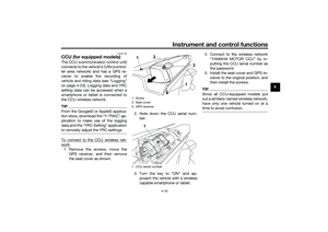 63
63 64
64 65
65 66
66 67
67 68
68 69
69 70
70 71
71 72
72 73
73 74
74 75
75 76
76 77
77 78
78 79
79 80
80 81
81 82
82 83
83 84
84 85
85 86
86 87
87 88
88 89
89 90
90 91
91 92
92 93
93 94
94 95
95 96
96 97
97 98
98 99
99 100
100 101
101 102
102 103
103 104
104 105
105 106
106 107
107 108
108 109
109 110
110 111
111 112
112 113
113 114
114 115
115 116
116 117
117 118
118 119
119 120
120 121
121 122
122 123
123 124
124 125
125 126
126 127
127 128
128 129
129 130
130 131
131 132
132 133
133 134
134 135
135