Page 57 of 136
The brake control system regulates hy-
draulic brake pressure for the front and
rear wheels independently when the
respective")
Instrument and control functions
4-34
4
EAU88462
Brake control system (BC)The brake control system regulates hy-
draulic brake pressure for the front and
rear wheels independently when the
respective brake lever or brake pedal is
applied and wheel lock is detected.
There are two settings, BC1 and BC2.
BC1 is standard ABS, which adjusts
brake pressure based on vehicle
speed and wheel speed data. BC1 is
designed to engage and maximize
braking when the vehicle is upright.
Regarding ABS, operate the brakes as
you would conventional brakes. When
the brake control system engages, a
pulsating sensation may be felt at the
brake lever or brake pedal as the hy-
draulic unit rapidly applies and reduces
brake pressure. In this situation, conti-
nue to apply the brake lever and brake
pedal to allow the ABS to work—do
not “pump the brakes” as this will re-
duce braking effectiveness.
WARNING
EWA16051
Always keep a sufficient distance
from the vehicle ahead to match the
riding speed even with ABS.
The ABS performs best with
long braking distances.
On certain surfaces, such as
rough or gravel roads, the brak-
ing distance may be longer with
the ABS than without.
BC2 incorporates standard ABS and in
addition regulates braking power when
cornering to suppress lateral wheel
slip.
WARNING
EWA20891
The brake control system is not a
substitute for the use of proper rid-
ing and braking techniques. The
brake control system cannot pre-
vent all loss of traction due to over-
braking from excessive speed, or
lateral wheel slip when braking on
slippery surfaces.The ABS hydraulic unit is monitored by
the ABS ECU, which will revert the sys-
tem to conventional braking if a mal-
function occurs.
TIPThe ABS performs a self-diagnosis test
when the vehicle is started and reach-
es a speed of 10 km/h (6 mi/h). During
this test, a clicking noise may be audi-
ble from the hydraulic control unit, and
a vibration may be felt at the brake le-
ver or pedal, but this is normal.NOTICE
ECA20100
Be careful not to damage the wheel
sensor or wheel sensor rotor; other-
wise, improper performance of the
ABS will result.1. Front wheel sensor rotor
2. Front wheel sensor
1
2
UB3LE1E0.book Page 34 Tuesday, August 10, 2021 2:28 PM
Page 58 of 136
Instrument and control functions
4-35
4
EAU13077
Fuel tank capTo open the fuel tank cap
Open the fuel tank cap lock cover, in-
sert the key, and then turn it 1/4 turn
clockwise. The lock will be released
and the fuel tank cap can be opened.
To close the fuel tank cap
With the key still inserted, push down
the fuel tank cap. Turn the key 1/4 turn
counterclockwise, remove it, and then
close the lock cover.
TIPThe fuel tank cap cannot be closed un-
less the key is in the lock. In addition,
the key cannot be removed if the cap is
not properly closed and locked.
WARNING
EWA11092
Make sure that the fuel tank cap is
properly closed after filling fuel.
Leaking fuel is a fire hazard.
1. Rear wheel sensor rotor
2. Rear wheel sensor
12
1. Fuel tank cap lock cover
2. UnlockK
1
2
UB3LE1E0.book Page 35 Tuesday, August 10, 2021 2:28 PM
Page 59 of 136

Instrument and control functions
4-36
4
EAU13222
FuelMake sure there is sufficient gasoline in
the tank.
WARNING
EWA10882
Gasoline and gasoline vapors are
extremely flammable. To avoid fires
and explosions and to reduce the
risk of injury when refueling, follow
these instructions.1. Before refueling, turn off the en-gine and be sure that no one is sit-
ting on the vehicle. Never refuel
while smoking, or while in the vi-
cinity of sparks, open flames, or
other sources of ignition such as
the pilot lights of water heaters
and clothes dryers.
2. Do not overfill the fuel tank. When refueling, be sure to insert the
pump nozzle into the fuel tank filler
hole. Stop filling when the fuel
reaches the bottom of the filler
tube. Because fuel expands when
it heats up, heat from the engine or
the sun can cause fuel to spill out
of the fuel tank. 3. Wipe up any spilled fuel immedi-
ately. NOTICE: Immediately
wipe off spilled fuel with a clean,
dry, soft cloth, since fuel may
deteriorate painted surfaces or
plastic parts.
[ECA10072]
4. Be sure to securely close the fuel tank cap.
WARNING
EWA15152
Gasoline is poisonous and can cau-
se injury or death. Handle gasoline
with care. Never siphon gasoline by
mouth. If you should swallow some
gasoline or inhale a lot of gasoline
vapor, or get some gasoline in your
eyes, see your doctor immediately. If gasoline spills on your skin, wash
with soap and water. If gasoline
spills on your clothing, change your
clothes.
EAU86072
Your Yamaha engine was designed to
use unleaded gasoline with a research
octane number of 95 or higher. If en-
gine knocking or pinging occurs, use a
gasoline of a different brand or higher
octane rating.
1. Fuel tank filler tube
2. Maximum fuel level
1
2
Recommended fuel:
Unleaded gasoline (E10 acceptable)
Octane number (RON): 95
Fuel tank capacity: 17 L (4.5 US gal, 3.7 Imp.gal)
Fuel tank reserve:
3.0 L (0.79 US gal, 0.66 Imp.gal)
UB3LE1E0.book Page 36 Tuesday, August 10, 2021 2:28 PM
Page 60 of 136
.
Confirm the gasoline pump nozzle
has the sam")
Instrument and control functions
4-37
4
TIPThis mark identifies the recom-
mended fuel for this vehicle as
specified by European regulation
(EN228).
Confirm the gasoline pump nozzle
has the same fuel identification
mark.Gasohol
There are two types of gasohol: gaso-
hol containing ethanol and that con-
taining methanol. Gasohol containing
ethanol can be used if the ethanol con-
tent does not exceed 10% (E10). Gas-
ohol containing methanol is not
recommended by Yamaha because it
can cause damage to the fuel system
or vehicle performance problems.
NOTICE
ECA11401
Use only unleaded gasoline. The use
of leaded gasoline will cause severe
damage to internal engine parts,
such as the valves and piston rings,
as well as to the exhaust system.
EAU86160
Fuel tank overflow hoseThe overflow hose drains excess gaso-
line and directs it safely away from the
vehicle.
Before operating the vehicle:
Check the fuel tank overflow hose
connection.
Check the fuel tank overflow hose
for cracks or damage, and replace
it if necessary.
Make sure that the fuel tank over-
flow hose is not blocked, and
clean it if necessary.
Make sure that the fuel tank over-
flow hose is positioned as shown.
E5
E10
1. Fuel tank overflow hose
2. White mark
1
2
UB3LE1E0.book Page 37 Tuesday, August 10, 2021 2:28 PM
Page 61 of 136
 to reduce harmful exhaust
emissions.
W")
Instrument and control functions
4-38
4
TIPSee page 7-13 for canister information.
EAU13435
Catalytic converterThe exhaust system contains catalytic
converter(s) to reduce harmful exhaust
emissions.
WARNING
EWA10863
The exhaust system is hot after op-
eration. To prevent a fire hazard or
burns: Do not park the vehicle near
possible fire hazards such as
grass or other materials that
easily burn.
Park the vehicle in a place
where pedestrians or children
are not likely to touch the hot
exhaust system.
Make sure that the exhaust sys-
tem has cooled down before
doing any maintenance work.
Do not allow the engine to idle
more than a few minutes. Long
idling can cause a build-up of
heat.
EAU79902
SeatsPassenger seat
To remove the passenger seat1. Insert the key into the seat lock,
and then turn it clockwise.
2. Lift the front of the passenger seat and pull it forward.
To install the passenger seat1. With the seat lock key still in the open position (turned clockwise),
insert the projection on the rear of
the passenger seat into the seat1. Seat lock
2. Unlock.
1
2
UB3LE1E0.book Page 38 Tuesday, August 10, 2021 2:28 PM
Page 62 of 136
Instrument and control functions
4-39
4holder as shown, and then push
the front of the seat down to lock
it in place.
2. Remove the key.
Rider seat
To remove the rider seat
1. Remove the passenger seat.
2. Pull up the corners on the rear of the rider seat, remove the bolts
with the hexagon wrench (see
page 7-2), and then pull the seat
off. To install the rider seat
1. Insert the projection into the seat
holder as shown, then place the
seat in the original position. 2. Install the bolts with the hexagon
wrench.
3. Insert the hexagon wrench back into its holder.
4. Install the passenger seat.
TIPMake sure that the seats are properly
secured before riding.
1. Projection
2. Seat holder
2
1
1. Bolt
1. Hexagon wrench
1
1
1. Projection
2. Seat holder
2 1
UB3LE1E0.book Page 39 Tuesday, August 10, 2021 2:28 PM
Page 63 of 136
Instrument and control functions
4-40
4
EAU67156
CCU (for equipped models)The CCU (communication control unit)
connects to the vehicle’s CAN (control-
ler area network) and has a GPS re-
ceiver to enable the recording of
vehicle and riding data (see “Logging”
on page 4-23). Logging data and YRC
setting data can be accessed when a
smartphone or tablet is connected to
the CCU wireless network.TIPFrom the Google
Page 64 of 136
Instrument and control functions
4-41
4
EAU88830
Seat cover (for equipped mod-
els)When the seat cover is attached, the
total number of occupants is reduced
to one person. Depending on your ar-
ea’s regulations, it may be necessary
to change the vehicle’s registration to
reflect this. Contact your local authori-
ties.
EAU66920
Document storageA document storage space is located
under panel B. (See page 7-9.)
When storing the owner’s manual or
vehicle registration and insurance do-
cuments in the document storage
space, be sure to wrap them in a plas-
tic bag so that they will not get wet.
When washing the vehicle, avoid let-
ting water enter the document storage
space.
NOTICE
ECA22540
Do not place heat-sensitive items in
the document storage space. This
space can get hot when the engine
is running or when the vehicle is in
direct sunlight.
1. Panel B
2. Document storage space
1
2
UB3LE1E0.book Page 41 Tuesday, August 10, 2021 2:28 PM
 1
1 2
2 3
3 4
4 5
5 6
6 7
7 8
8 9
9 10
10 11
11 12
12 13
13 14
14 15
15 16
16 17
17 18
18 19
19 20
20 21
21 22
22 23
23 24
24 25
25 26
26 27
27 28
28 29
29 30
30 31
31 32
32 33
33 34
34 35
35 36
36 37
37 38
38 39
39 40
40 41
41 42
42 43
43 44
44 45
45 46
46 47
47 48
48 49
49 50
50 51
51 52
52 53
53 54
54 55
55 56
56 57
57 58
58 59
59 60
60 61
61 62
62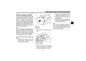 63
63 64
64 65
65 66
66 67
67 68
68 69
69 70
70 71
71 72
72 73
73 74
74 75
75 76
76 77
77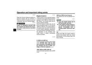 78
78 79
79 80
80 81
81 82
82 83
83 84
84 85
85 86
86 87
87 88
88 89
89 90
90 91
91 92
92 93
93 94
94 95
95 96
96 97
97 98
98 99
99 100
100 101
101 102
102 103
103 104
104 105
105 106
106 107
107 108
108 109
109 110
110 111
111 112
112 113
113 114
114 115
115 116
116 117
117 118
118 119
119 120
120 121
121 122
122 123
123 124
124 125
125 126
126 127
127 128
128 129
129 130
130 131
131 132
132 133
133 134
134 135
135

The CCU (communication control unit)
connects to the vehicle’s CAN (control-
ler area network) and has a GPS re-
ceiver to e")
When the seat cover is attached, the
total number of occupants is reduced
to one person. Depending on your ar-
ea’s")