Page 57 of 92

Periodic maintenance an d a djustment
7-7
7
To install the spark plu
g
1. Clean the surface of the spark plug gasket and its mating sur-
face, and then wipe off any grime
from the spark plug threads.
2. Install the spark plug with the spark plug wrench, and then tight-
en it to the specified torque.
TIP
If a torque wrench is not available
when installing a spark plug, a good
estimate of the correct torque is 1/4…
1/2 turn past finger tight. However, the
spark plug should be tightened to the
specified torque as soon as possible.
3. Install the spark plug cap asshown.
EAU4144C
Transmission oil
The transmission must be checked for
oil leakage before each ride. If any
leakage is found, have a Yamaha deal-
er check and repair the motorcycle. In
addition, the transmission oil must be
changed at the intervals specified in
the periodic maintenance and lubrica-
tion chart.1. Start the engine, warm it up for several minutes, and then turn it
off.
2. Place the motorcycle on a level surface and hold it in an upright
position.
3. Place an oil pan under the trans- mission case to collect the used
oil.
4. Remove the transmission oil filler cap and its O-ring, and then re-
move the transmission oil drain
bolt and its gasket to drain the oil
from the transmission.
5. Install the drain bolt and its new gasket, and then tighten the bolt
to the specified torque.
Tightening torque:
Spark plug: 20 N·m (2.0 kgf·m, 15 lb·ft)
1. Spark plug cap
1
1. Transmission oil filler cap
2. O-ring
3. Transmission oil drain bolt
4. Gasket
1
2
43
UBR882E0.book Page 7 Wednesd ay, February 26, 2020 11:39 AM
Page 58 of 92

Periodic maintenance an d a djustment
7-8
7 6. Refill with the specified amount of
the recommended transmission
oil.
NOTICE
ECA10453
In or der to prevent clutch slip-
pa ge (since the transmission oil
also lu bricates the clutch), d o
not mix any chemical additives.
Do not use oils with a diesel
specification of “CD” or oils of a
hi gher quality than specifie d. In
a ddition, do not use oils la bele d
“ENERGY CONSERVING II” or
hi gher.
Make sure that no forei gn mate-
rial enters the transmission.
7. Check the O-ring for damage, and replace it if necessary.
8. Install and tighten the transmis- sion oil filler cap and its O-ring.
9. Start the engine, and then let it idle for several minutes while checking
it for oil leakage. If oil is leaking,
immediately turn the engine off
and check for the cause.
EAU20071
Coolant
The coolant level should be checked
before each ride. In addition, the cool-
ant must be changed at the intervals
specified in the periodic maintenance
and lubrication chart.
EAUM1296To check the coolant level1. Place the vehicle on a level sur- face and hold it in an upright posi-
tion.
TIP
The coolant level must be
checked on a cold engine since
the level varies with engine tem-
perature.
Make sure that the vehicle is posi-
tioned straight up when checking
the coolant level. A slight tilt to the
side can result in a false reading.
2. Remove the radiator cap and
check the coolant level in the radi-
ator. WARNING! Never attempt
to remove the ra diator cap
when the en gine is hot.
[EWA10382]
Ti ghtenin g torque:
Transmission oil drain bolt: 10 N·m (1.0 kgf·m, 7.4 lb·ft)
Recommen ded transmission oil:
Motor oil SAE 10W-30 type SE or
higher or Gear oil SAE 85W GL-3
Oil chan ge quantity:
0.50 L (0.53 US qt, 0.44 Imp.qt)
1. Radiator cap
1
UBR882E0.book Page 8 Wednesd ay, February 26, 2020 11:39 AM
Page 59 of 92

Periodic maintenance an d a djustment
7-9
7
TIP
The coolant should be at the bottom of
the radiator filler neck. The level will
change with variation of engine tem-
perature.
3. If the coolant is below the correct
coolant level, add coolant, and
then install the radiator cap.
NOTICE: If coolant is not avail-
a b le, use distille d water or soft
tap water instead . Do not use
har d water or salt water since it
is harmful to the en gine. If water
has been used instead of cool-
ant, replace it with coolant as
soon as possi ble, otherwise the
coolin g system will not be pro-
tected against frost an d corro-
sion. If water has b een added to
the coolant, have a Yamaha
d ealer check the antifreeze con-
tent of the coolant as soon as
possi ble, otherwise the effec-
tiveness of the coolant will be
re duce d.
[ECA10473]
EAUM1318
To change the coolant
1. Place the vehicle on a level sur- face and let the engine cool if nec-
essary. 2. Place a container under the en-
gine to collect the used coolant.
3. Remove the radiator cap, and then the coolant drain bolt and its
gasket to drain the cooling sys-
tem. WARNING! Never attempt
to remove the ra diator cap
when the en gine is hot.
[EWA10382]
4. After the coolant is completely
drained, thoroughly flush the cool-
ing system with clean tap water.
5. Install the coolant drain bolt and its new gasket, and then tighten
the bolt to the specified torque.
1. Correct coolant level
1
1. Radiator cap
1. Coolant drain bolt
2. Gasket
Tightenin g torque:
Coolant drain bolt: 10 N·m (1.0 kgf·m, 7.4 lb·ft)
1
21
UBR882E0.book Page 9 Wednesd ay, February 26, 2020 11:39 AM
Page 60 of 92

Periodic maintenance an d a djustment
7-10
7 6. Pour the recommended coolant
into the radiator until it is full.
7. Install the radiator cap, start the engine, let it idle for several min-
utes, and then turn it off.
8. Remove the radiator cap to check the coolant level in the radiator. If
necessary, add sufficient coolant
until it reaches the bottom of the
radiator filler neck, and then install
the radiator cap.
9. Start the engine, and then check the vehicle for coolant leakage. If
coolant is leaking, have a Yamaha
dealer check the cooling system.
EAU84100
Cleanin g the air filter element
Clean or replace the air filter element at
the intervals specified in the periodic
maintenance and lubrication chart.
Service the air filter element more fre-
quently if you often ride in wet or dusty
conditions.
1. Remove the seat. (See page 4-8.)
2. Remove the air filter element by removing the wing bolt and its
washer.
3. Remove the sponge material from the air filter element frame.
4. Clean the sponge material with solvent or YAMALUBE foam air fil-
ter cleaner, and then squeeze out
the remaining liquid.
Antifreeze/water mixture ratio:1:1
Recommen ded antifreeze:
High-quality ethylene glycol anti-
freeze containing corrosion inhibi-
tors for aluminum engines
Coolant quantity:
Radiator (including all routes):0.38 L (0.40 US qt, 0.33 Imp.qt)
1. Wing bolt
2. Washer
3. Air filter element
1. Sponge material
2. Air filter element frame
1
2
3
1
2
UBR882E0.book Page 10 Wednesday, February 26, 2020 11:39 AM
Page 61 of 92

Periodic maintenance an d a djustment
7-11
7
5. Apply YAMALUBE foam air filter
oil to the entire surface of the
sponge material, and then
squeeze out the excess oil.
TIP
The sponge material should be
wet but not dripping.
If YAMALUBE foam air filter oil is
not available in your area, another
high-quality foam air filter oil may
be used instead.
6. Pull the sponge material over the
air filter element frame.
7. Insert the air filter element into the air filter case by aligning the pro-
jection on the element with the slot
in the case, and then install the
wing bolt and its washer.
NOTICE: Make sure that the air
filter element is properly seated
in the air filter case. The en gine
shoul d never b e operated with-
out the air filter element in-
stalle d, otherwise the piston(s)
an d/or cylin der(s) may become
excessively worn.
[ECA10482]
NOTICE: Be sure to install the
washer with its curve d si de fac-
in g outwar d as shown.
[ECA16692]
8. Install the seat.
1. Slot
2. Projection
1. Washer
1 2
1
UBR882E0.book Page 11 Wednesday, February 26, 2020 11:39 AM
Page 62 of 92

Periodic maintenance an d a djustment
7-12
7
EAU42111
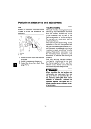
A djustin g the car buretor
The carburetor is an important part of
the engine and requires very sophisti-
cated adjustment. Therefore, most
carburetor adjustments should be left
to a Yamaha dealer, who has the nec-
essary professional knowledge and ex-
perience. The adjustment described in
the following section, however, may be
serviced by the owner as part of rou-
tine maintenance.
NOTICE
ECA10551
The car buretor has b een set and ex-
tensively teste d at the Yamaha fac-
tory. Chan gin g these settin gs
without sufficient technical knowl-
e dge may result in poor perfor-
mance of or damag e to the en gine.
EAU44391
A djustin g the eng ine idlin g
spee d
The engine idling speed must be ad-
justed when necessary.
1. Start the engine and thoroughly warm it up.
2. Turn the throttle stop screw until the engine runs at the lowest pos-
sible speed.
3. To increase the engine idling speed, turn the throttle stop screw
in direction (a). To decrease the
engine idling speed, turn the throt-
tle stop screw in direction (b).
1. Throttle stop screw
1
(b)(a)
UBR882E0.book Page 12 Wednesday, February 26, 2020 11:39 AM
Page 63 of 92
Periodic maintenance an d a djustment
7-13
7
EAU48434
A djustin g the throttle grip free
play
Measure the throttle grip free play as
shown.
Periodically check the throttle grip free
play and, if necessary, adjust it as fol-
lows.
TIP
The engine idling speed must be cor-
rectly adjusted before checking and
adjusting the throttle grip free play.
1. Slide the rubber cover back.
2. Loosen the locknut.
3. To increase the throttle grip free
play, turn the adjusting nut in di-
rection (a). To decrease the throt-
tle grip free play, turn the adjusting
nut in direction (b). 4. Tighten the locknut and then slide
the rubber cover to its original po-
sition.
1. Throttle grip free play
Throttle g rip free play:
3.0–6.0 mm (0.12–0.24 in)
1. Locknut
2. Throttle grip free play adjusting nut
3. Rubber cover
1 2
3
(a)
(b)
UBR882E0.book Page 13 Wednesday, February 26, 2020 11:39 AM
Page 64 of 92

Periodic maintenance an d a djustment
7-14
7
EAU65042
Tires
Tires are the only contact between the
vehicle and the road. Safety in all con-
ditions of riding depends on a relatively
small area of road contact. Therefore, it
is essential to maintain the tires in good
condition at all times and replace them
at the appropriate time with the speci-
fied tires.
Tire air pressure
The tire air pressure should be
checked and, if necessary, adjusted
before each ride.
WARNING
EWA14382
Operation of this vehicle with im-
proper tire pressure may cause se-
vere injury or death from loss of
control. The tire air pressure must be
checked and a djuste d on col d
tires (i.e., when the temperature
of the tires equals the am bient
temperature).
The tire air pressure must be
a d juste d in accor dance with the
wei ght of the ri der, the ri din g
speed , and the ri din g con di-
tions.
Tire inspection
The tires must be checked before each
ride.
NOTICE
ECA15582
Make sure the bead stopper is
ti g htene d. A loose b ead stopper
will cause the tire to slip off the
rim if tire pressure is too low.
Make sure the valve stem is po-
sitione d straig ht. A tilte d valve
stem in dicates that the tire has
slippe d from its ori ginal position
on the rim. Rotate the tire so
that the valve stem is positioned
straig ht.
If the center tread depth reaches the
specified limit, if the tire has a nail or
glass fragments in it, or if the sidewall
is cracked, have a Yamaha dealer re-
place the tire immediately.
Tire information
This model is equipped with tube tires.
Standar d tire air pressure:
Front: 100 kPa (1.00 kgf/cm², 15 psi)
Rear:
100 kPa (1.00 kgf/cm², 15 psi)
1. Tire sidewall
2. Tire tread depth
Minimum tire trea d d epth (front an d
rear):
4.0 mm (0.16 in)
1
2
UBR882E0.book Page 14 Wednesday, February 26, 2020 11:39 AM