Page 59 of 618

57
1
CV Owner's Manual_Europe_M52N20_en
1-2. Child safety
For safety and security
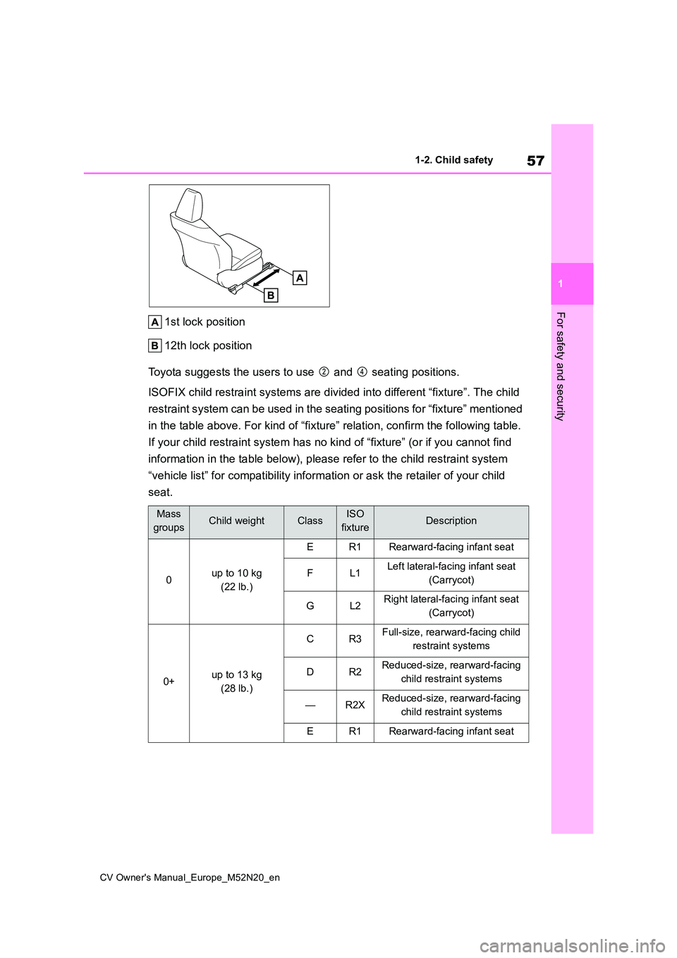
1st lock position
12th lock position
Toyota suggests the users to use and seating positions.
ISOFIX child restraint systems are divided into different “fixt ure”. The child
restraint system can be used in the seating positions for “fixt ure” mentioned
in the table above. For kind of “ fixture” relation, confirm the following table.
If your child restraint system ha s no kind of “fixture” (or if you cannot find
information in the table below), please refer to the child rest raint system
“vehicle list” for compatibility information or ask the retaile r of your child
seat.
Mass
groupsChild weightClassISO
fixtureDescription
0up to 10 kg
(22 lb.)
ER1Rearward-facing infant seat
FL1Left lateral-facing infant seat
(Carrycot)
GL2Right lateral-facing infant seat
(Carrycot)
0+up to 13 kg
(28 lb.)
CR3Full-size, rearward-facing child
restraint systems
DR2Reduced-size, rearward-facing
child restraint systems
—R2XReduced-size, rearward-facing
child restraint systems
ER1Rearward-facing infant seat
Page 63 of 618

61
1
CV Owner's Manual_Europe_M52N20_en
1-2. Child safety
For safety and security
is not in the table), refer to the
“Vehicle List” provided by the child
restraint system maker for various
possible installation positions, or
check the compatibility after asking
the retailer of the child seat.
( P.53, 54)
1 If installing the child restraint
system to the front passenger
seat is unavoidable, refer to
P.50 for the front passenger seat
adjustment.
2 If the head restraint interferes
with your child restraint system,
and the head restraint can be
removed, remove the head
restraint. Otherwise, put the
head restraint in the upper most
position. ( P.144)
3 Run the seat belt through the
child restraint system and insert
the plate into the buckle. Make
sure that the belt is not twisted.
Securely fix the seat belt to the
child restraint system in accor-
dance to the directions enclosed
with the child restraint system.
4 If your child restraint system is
not equipped with a lock-off (a
seat belt locking feature),
s e c u r e t h e c h i l d r e s t r a i n t s y s t e m
using a locking clip.
5 After installing the child restraint
system, rock it back and forth to
ensure that it is installed
securely. ( P. 6 2 )
■Removing a child restraint
system installed with a seat
belt
Press the buckle release button
and fully retract the seat belt.
When releasing the buckle, the child
restraint system may spring up due to
the rebound of the seat cushion.
Release the buckle while holding down
the child restraint system.
Since the seat belt automatically reels
itself, slowly return it to the stowing
position.
■When installing a child restraint system
You may need a locking clip to install the child restraint system. Follow the
instructions provided by the manufac- turer of the system. If your child restraint system does not provide a locking clip,
you can purchase the following item from any authorized Toyota retailer or Toyota authorized repairer, or any reli-
able repairer: Locking clip for child restraint system
Page 64 of 618

62
CV Owner's Manual_Europe_M52N20_en
1-2. Child safety
(Part No. 73119-22010)
■ISOFIX lower anchorages
(ISOFIX child restraint system)
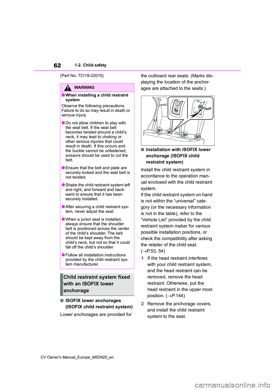
Lower anchorages are provided for
the outboard rear seats. (Marks dis-
playing the location of the anchor-
ages are attached to the seats.)
■Installation with ISOFIX lower
anchorage (ISOFIX child
restraint system)
Install the child restraint system in
accordance to the operation man-
ual enclosed with the child restraint
system.
If the child restraint system on hand
is not within the “universal” cate-
gory (or the necessary information
is not in the table), refer to the
“Vehicle List” provided by the child
restraint system maker for various
possible installation positions, or
check the compatibility after asking
the retailer of the child seat.
( P.53, 54)
1 If the head restraint interferes
with your child restraint system,
and the head restraint can be
removed, remove the head
restraint. Otherwise, put the
head restraint in the upper most
position. ( P.144)
2 Remove the anchorage covers,
and install the child restraint
system to the seat.
WARNING
■When installing a child restraint system
Observe the following precautions.
Failure to do so may result in death or serious injury.
●Do not allow children to play with the seat belt. If the seat belt becomes twisted around a child’s
neck, it may lead to choking or other serious injuries that could result in death. If this occurs and
the buckle cannot be unfastened, scissors should be used to cut the belt.
●Ensure that the belt and plate are securely locked and the seat belt is
not twisted.
●Shake the child restraint system left
and right, and forward and back- ward to ensure that it has been securely installed.
●After securing a child restraint sys-tem, never adjust the seat.
●When a junior seat is installed, always ensure that the shoulder
belt is positioned across the center of the child’s shoulder. The belt should be kept away from the
child’s neck, but not so that it could fall off the child’s shoulder.
●Follow all installation instructions provided by the child restraint sys-tem manufacturer.
Child restraint system fixed
with an ISOFIX lower
anchorage
Page 74 of 618
72
CV Owner's Manual_Europe_M52N20_en
1-3. Emergency assistance
2.5. Modalities for exercising data subject’s rights
2.5.1.
The data subject (the vehicle’s owner) has a right
of access to data and as appropriate to request
the rectification, erasure or blocking of data, con-
cerning him or her, the processing of which does
not comply with the provisions of Directive
95/46/EC. Any third parties to whom the data
have been disclosed have to be notified of such
rectification, erasure or blocking carried out in
compliance with this Directive, unless it proves
impossible or involves a disproportionate effort.
O
2.5.2.
The data subject has a right to complain to the
competent data protection authority if he or she
considers that his or her rights have been
infringed as a result of the processing of his or
her personal data.
O
2.5.3.
Contact service responsible for handling access
requests (if any):
P. 7 3
O
Implementing Regulation Annex1 PART3 User InformationConformity
Page 78 of 618

76
CV Owner's Manual_Europe_M52N20_en
1-4. Theft deterrent system
*: If equipped
■Setting
Turn the engine switch off, have all
the passengers exit the vehicle and
ensure that all the doors are closed.
Using the entry function (if
equipped): Touch the sensor area
on the outside door handle twice
within 5 seconds.
Using the wireless remote control:
Press twice within 5 seconds.
■Canceling
Using the entry function (if
equipped): Hold the outside door
handle.
Using the wireless remote control:
Press .
Using power back door (if
equipped): Using wireless remote
control ( P.126), or using Hands
Free Power Back Door ( P. 1 2 8 ) .
Double locking system*
Unauthorized access to the
vehicle is prevented by dis-
abling the door unlocking
function from both the interior
and exterior of the vehicle.
Vehicles employing this sys-
tem have labels on the window
glass of both front doors.
Setting/canceling the double
locking system
WARNING
■Double locking system precau- tion
Never activate the double locking sys-
tem when there are people in the vehicle because all the doors cannot be opened from inside the vehicle.
Page 79 of 618

77
1
CV Owner's Manual_Europe_M52N20_en
1-4. Theft deterrent system
For safety and security
*: If equipped
■Items to check before locking
the vehicle
To prevent unexpected triggering of
the alarm and vehicle theft, make
sure of the following:
Nobody is in the vehicle.
The windows are closed before
the alarm is set.
No valuables or other personal
items are left in the vehicle.
■Setting
Close the door and hood, and lock
all the doors using the entry func-
tion (if equipped) or wireless
remote control. The system will set
automatically after 30 seconds.
The indicator light changes from being
on to flashing when the system is set.
■Canceling or stopping
Do one of the following to deacti-
vate or stop the alarms:
Unlock the doors using the entry
function (if equipped) or wireless
remote control.
Starting the engine. (The alarm
will be deactivated or stopped
after a few seconds.)
■Setting the alarm
The alarm can be set if all the doors are closed even with the hood open.
■System maintenance
The vehicle has a maintenance-free type alarm system.
■Triggering of the alarm
The alarm may be triggered in the fol-
lowing situations: (Stopping the alarm deactivates the alarm system.)
●The doors are unlocked using the key or the mechanical key.
Alarm*
The alarm uses light and
sound to give an alert when an
intrusion is detected.
The alarm is triggered in the
following situations when the
alarm is set:
A locked door is unlocked or
opened in any way other than
using the entry function (if
equipped) or wireless remote
control. (The doors will lock
again automatically.)
The hood is opened.
Setting/canceling/stopping
the alarm system
Page 80 of 618
78
CV Owner's Manual_Europe_M52N20_en
1-4. Theft deterrent system
●A person inside the vehicle opens a
door or hood, or unlocks the vehicle.
●The battery is recharged or replaced
when the vehicle is locked. ( P.440)
■Alarm-operated door lock
In the following cases, depending on the situation, the door may automatically
lock to prevent improper entry into the vehicle:
●When a person remaining in the vehi-cle unlocks the door and the alarm is activated.
●While the alarm is activated, a person remaining in the vehicle unlocks the
door.
●When recharging or replacing the bat-
tery
■Customization
Some functions can be customized. ( P.457)
NOTICE
■To ensure the system operates correctly
Do not modify or remove the system. If modified or removed, the proper operation of the system cannot be
guaranteed.
Page 87 of 618
85
2
CV Owner's Manual_Europe_M52N20_en
2-1. Instrument cluster
Vehicle status information and indicators
■Locations of gauges and meters
The units of measure may differ depending on the intended destination of the vehi-
cle.
Tachometer
Displays the engine speed in revolutions per minute
Multi-information display
Presents the driver with a variety of vehicle data ( P. 9 4 )
Displays warning messages if a malfunction occurs ( P.413)
Clock (P.87, 88)
Speedometer
Displays the vehicle speed
Engine coolant temperature gauge
Displays the engine coolant temperature
Fuel gauge
Displays the fuel level. In the following situations, the actua l fuel level may not be
displayed correctly:
• After refueling only a small amount (approximately 5 L or less )
Gauges and meters (4.2-inch display)
The meters display various drive information.
Meter display