2022 TOYOTA TUNDRA HYBRID mirror
[x] Cancel search: mirrorPage 216 of 618

2164-3. Operating the lights and wipers
Owners Manual_USA_M0C031_ensandstorms, etc.)
• The windshield is obscured by fog, mist, ice, dirt, etc.
• The windshield is cracked or dam- aged
• The front camera is deformed or
dirty
• When the temperature of the front camera is extremely high
• Surrounding brightness levels are equal to those of h eadlights, tail
lights or fog lights
• When headlights or tail lights of vehicles ahead are turned off,
dirty, changing color, or not aimed
properly
• When the vehicle is hit by water, snow, dust, etc. from a preceding
vehicle
• When driving thr ough an area of
intermittently changing brightness
and darkness
• When frequently and repeatedly driving ascending/descending
roads, or roads with rough, bumpy
or uneven surfaces (such as
stone-paved roads, gravel roads,
etc.)
• When frequently and repeatedly taking curves or driving on a wind-
ing road
• There is a highly reflective object
ahead of the vehicle, such as a
sign or mirror
• The back of a vehicle ahead is highly reflective, such as a con-
tainer on a truck
• The vehicle’s headlights are dam- aged or dirty, or are not aimed
properly
• The vehicle is listing or titling due to a flat tire, a trailer being towed,
etc.
• The high beam and low beam are repeatedly being switched
between in an abnormal manner
• The driver believes that the high beam may be causing problems
or distress to other drivers or
pedestrians nearby
■Temporarily lowering sensor
sensitivity
The sensitivity of the sensor can be temporarily lowered.
1
Turn the power s witch off while
the following conditions are met.
●The headlight switch is in or
.
●The headlight switch lever is in
low beam position.
●Automatic High Beam switch is
on.
2 Turn the power switch to ON.
3 Within 60 seconds after step 2,
repeat pushing the headlight
switch lever to the high beam
position then pulling it to the orig-
inal position quickly 10 times,
then leave the lever in the origi-
nal position.
4 If the sensitivity is changed, the
AHB indicator is turn on and off 3
times.
Automatic High Beam (headlights)
may turn on even when the vehicle
is stopped.
■Switching to the high
beams
Push the lever away from you.
The AHB indicator will turn off and
the high beam indi cator will turn on.
Pull the lever to its original position
to activate the Automatic High
Beam system.
Turning the high beams
on/off manually
Page 227 of 618
2274-5. Using the driving support systems
Owners Manual_USA_M0C031_en
4
Driving
■Certification
P.612
WARNING
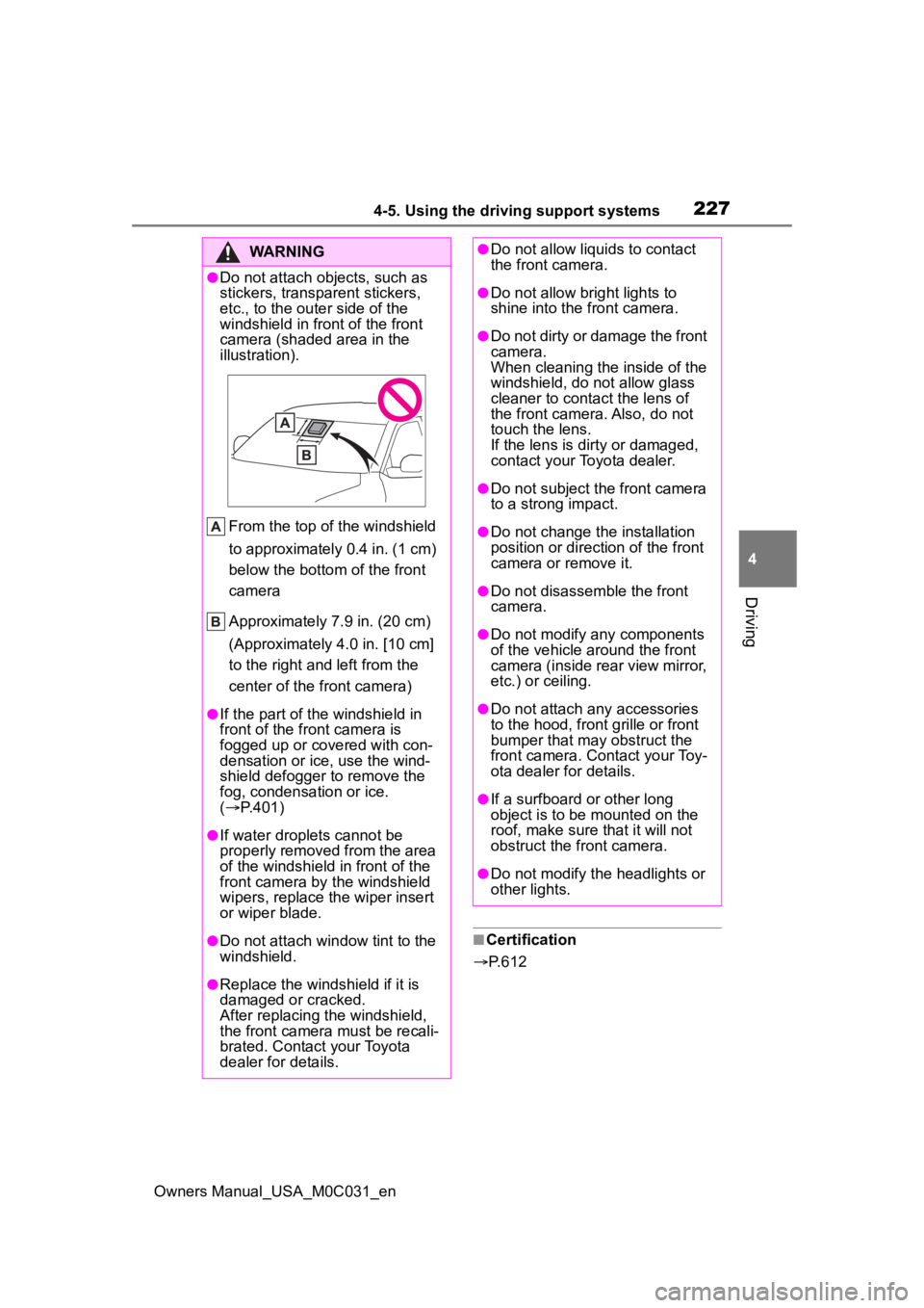
●Do not attach objects, such as
stickers, transparent stickers,
etc., to the oute r side of the
windshield in fr ont of the front
camera (shaded area in the
illustration).
From the top of the windshield
to approximately 0.4 in. (1 cm)
below the bottom of the front
camera
Approximately 7.9 in. (20 cm)
(Approximately 4.0 in. [10 cm]
to the right and left from the
center of the front camera)
●If the part of the windshield in
front of the front camera is
fogged up or covered with con-
densation or ice, use the wind-
shield defogger to remove the
fog, condensation or ice.
( P.401)
●If water droplets cannot be
properly removed from the area
of the windshield in front of the
front camera by the windshield
wipers, replace the wiper insert
or wiper blade.
●Do not attach win dow tint to the
windshield.
●Replace the windshield if it is
damaged or cracked.
After replacing the windshield,
the front camera must be recali-
brated. Contact your Toyota
dealer for details.
●Do not allow liquids to contact
the front camera.
●Do not allow bright lights to
shine into the front camera.
●Do not dirty or damage the front
camera.
When cleaning the inside of the
windshield, do not allow glass
cleaner to contact the lens of
the front camera. Also, do not
touch the lens.
If the lens is dirty or damaged,
contact your Toyota dealer.
●Do not subject the front camera
to a strong impact.
●Do not change the installation
position or direction of the front
camera or remove it.
●Do not disassemble the front
camera.
●Do not modify any components
of the vehicle around the front
camera (inside rear view mirror,
etc.) or ceiling.
●Do not attach any accessories
to the hood, front grille or front
bumper that may obstruct the
front camera. Contact your Toy-
ota dealer for details.
●If a surfboard or other long
object is to be mounted on the
roof, make sure that it will not
obstruct the front camera.
●Do not modify the headlights or
other lights.
Page 267 of 618

2674-5. Using the driving support systems
Owners Manual_USA_M0C031_en
4
Driving
Meter control switches
Turning the Blind Spot Monitor
on/off.
Outside rear view mirror indi-
cators
When a vehicle is detected in a
blind spot of the outside rear view
mirrors or approaching rapidly from
behind into a blind spot, the outside
rear view mirror indicator on the
detected side will illuminate. If the
turn signal lever is operated toward
the detected side, the outside rear
view mirror indicator flashes.
■Outside rear vie w mirror indica-
tor visibility
In strong sunlight, the outside rear
view mirror indicator may be difficult
to see.
■When “Blind Spot Monitor
Unavailable” is shown on the
multi-information display
Ice, snow, mud, etc., may be
attached to the rear bumper around
the sensors. ( P.269) The system
should return to normal operation
after removing the ice, snow, mud,
etc., from the rear bumper. Addition-
ally, the sensors may not operate
normally when drivin g in extremely
hot or cold environments.
BSM (Blind Spot Moni-
tor)
The Blind Spot Monitor is a
system that uses rear side
radar sensors installed on
the inner side of the rear
bumper on the left and right
side to assist the driver for
lane changing decision.
WARNING
■Cautions regarding the use of
the system
The driver is solely responsible for
safe driving. Always drive safely,
taking care to o bserve your sur-
roundings.
The Blind Spot Monitor is a sup-
plementary function which alerts
the driver that a v ehicle is in a
blind spot of the outside rear view
mirrors or is approaching rapidly
from behind into a blind spot. Do
not overly rely on the Blind Spot
Monitor. As the function cannot
judge if it is safe to change lanes,
over reliance could lead to an
accident resulting in death or seri-
ous injury.
As the system may not function
correctly under certain condi-
tions, the driver’s own visual con-
firmation of safety is necessary.
System components
Page 270 of 618

2704-5. Using the driving support systems
Owners Manual_USA_M0C031_enbusy parking lot, area surrounded
with trees (camping ground) or in
an environment with objects in the
immediate environment that pre-
vent sensors from sufficiently
detecting the trailer.
■Trailer Length Detection (TLD)
●Once a trailer is detected and if
the trailer length in the meter is
selected as “Auto”, the TLD func-
tion will estimate the
trailer length
using the Blind Spot Monitor sen-
sors. In order to estimate
the trailer length
with TLD function and detection
area, make at least two 90 degree
turns.
If the trailer length is entered manu-
ally via multi-information display
input, the detection area is also
adjusted to exceed the length of the
trailer.
●Depending on some trailer types
and the dimensions of the trailer
TMW performance may be
degraded.
■Vehicles that can be detected by the Blind Spot Monitor
The Blind Spot Monitor uses rear side radar sensors to detect the fol-
lowing vehicles traveling in adjacent lanes and advises the dri ver of
the presence of such vehicles v ia the indicators on the outside rear
view mirrors.
When not towing a trailer
Vehicles approaching in adjacen t lanes that may not be visible
using the outside rear view mirrors (the blind spots)
Vehicles that are approaching r apidly in adjacent lanes that are
not visible using the outside rear view mirrors (the blind spots)
When towing a trailer
Blind Spot Monitor operation
Page 271 of 618
2714-5. Using the driving support systems
Owners Manual_USA_M0C031_en
4
Driving
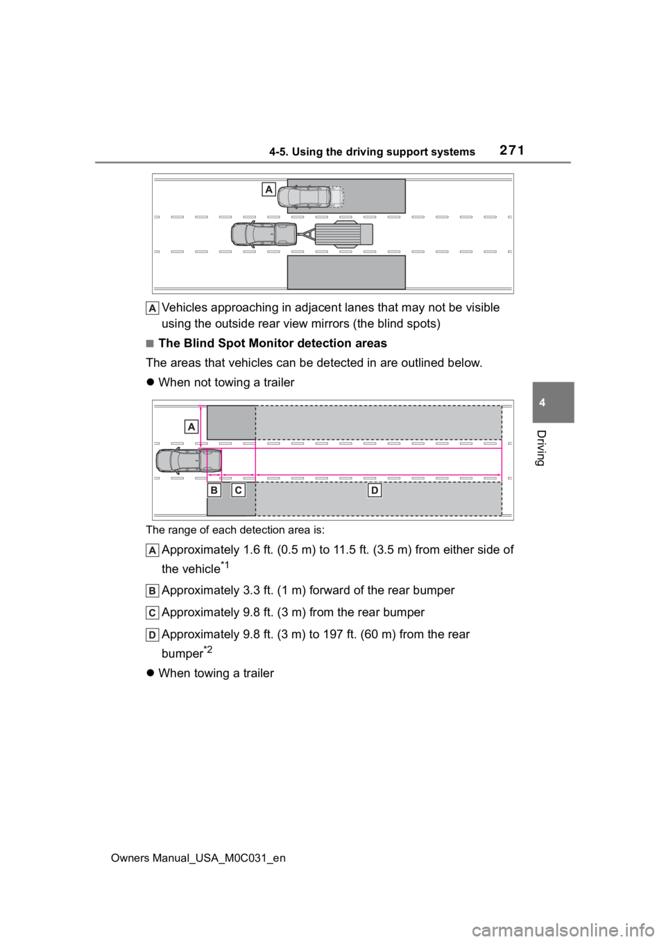
Vehicles approaching in adjacen t lanes that may not be visible
using the outside rear view mirrors (the blind spots)
■The Blind Spot Monitor detection areas
The areas that vehicles can be detected in are outlined below.
When not towing a trailer
The range of each detection area is:
Approximately 1.6 ft. (0.5 m) to 11.5 ft. (3.5 m) from either s ide of
the vehicle
*1
Approximately 3.3 ft. (1 m) forward of the rear bumper
Approximately 9.8 ft. (3 m) from the rear bumper
Approximately 9.8 ft. (3 m) to 197 ft. (60 m) from the rear
bumper
*2
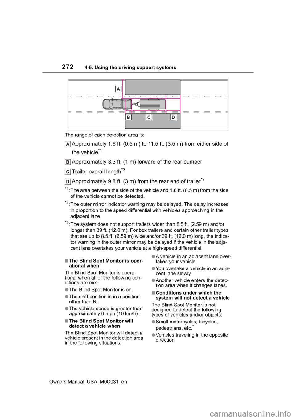
When towing a trailer
Page 272 of 618
2724-5. Using the driving support systems
Owners Manual_USA_M0C031_enThe range of each detection area is:
Approximately 1.6 ft. (0.5 m) to 11.5 ft. (3.5 m) from either s
ide of
the vehicle
*1
Approximately 3.3 ft. (1 m) forward of the rear bumper
Trailer overall length
*3
Approximately 9.8 ft. (3 m) from the rear end of trailer*3
*1: The area between the side of the vehicle and 1.6 ft. (0.5 m) f rom the side
of the vehicle cannot be detected.
*2: The outer mirror indicator warning may be delayed. The delay i ncreases
in proportion to the speed differential with vehicles approaching in the
adjacent lane.
*3: The system does not support trailers wider than 8.5 ft. (2.59 m) and/or
longer than 39 ft. (12.0 m). For box trailers and certain other trailer types
that are up to 8.5 ft. (2.59 m) wide and/or 39 ft. (12.0 m) lon g, the indica-
tor warning in t he outer mirror may be de layed if the vehicle in the adja-
cent lane overtakes your vehicle at a high-speed differential.
■The Blind Spot Monitor is oper-
ational when
The Blind Spot Monitor is opera-
tional when all of the following con-
ditions are met:
●The Blind Spot Monitor is on.
●The shift position is in a position
other than R.
●The vehicle speed is greater than
approximately 6 mph (10 km/h).
■The Blind Spot Monitor will
detect a veh icle when
The Blind Spot Mon itor will detect a
vehicle present in the detection area
in the followin g situations:
●A vehicle in an adjacent lane over-
takes your vehicle.
●You overtake a vehicle in an adja-
cent lane slowly.
●Another vehicle enters the detec-
tion area when it changes lanes.
■Conditions under which the
system will not detect a vehicle
The Blind Spot Monitor is not
designed to detect the following
types of vehicles and/or objects:
●Small motorcycles, bicycles,
pedestrians, etc.*
●Vehicles traveling in the opposite
direction
Page 282 of 618
2824-5. Using the driving support systems
Owners Manual_USA_M0C031_en
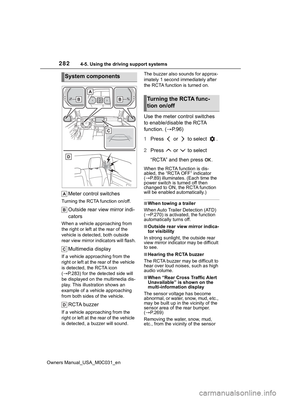
Meter control switches
Turning the RCTA function on/off.
Outside rear view mirror indi-
cators
When a vehicle approaching from
the right or left at the rear of the
vehicle is detected, both outside
rear view mirror i ndicators will flash.
Multimedia display
If a vehicle approaching from the
right or left at the rear of the vehicle
is detected, the RCTA icon
( P.283) for the det ected side will
be displayed on the multimedia dis-
play. This illustration shows an
example of a vehicle approaching
from both sides of the vehicle.
RCTA buzzer
If a vehicle appr oaching from the
right or left at the rear of the vehicle
is detected, a b uzzer will sound. The buzzer also sounds for approx-
imately 1 second immediately after
the RCTA function is turned on.
Use the meter control switches
to enable/disable the RCTA
function. (
P.96)
1 Press or to select .
2 Press or to select
“RCTA” and then press .
When the RCTA function is dis-
abled, the “RCTA OFF” indicator
( P.89) illuminates. (Each time the
power switch is turned off then
changed to ON, t he RCTA function
will be enabled a utomatically.)
■When towing a trailer
When Auto Trailer Detection (ATD)
( P.270) is activated, the function
automatically turns off.
■Outside rear vie w mirror indica-
tor visibility
In strong sunlight, the outside rear
view mirror indicator may be difficult
to see.
■Hearing the RCTA buzzer
The RCTA buzzer may be difficult to
hear over loud noises, such as high
audio volume.
■When “Rear Cross Traffic Alert
Unavailable” is shown on the
multi-information display
The sensor voltage has become
abnormal, or water, snow, mud, etc.,
may be built up in th e vicinity of the
sensor area of the rear bumper.
( P.269)
Removing the water, snow, mud,
etc., from the vicini ty of the sensor
System components
Turning the RCTA func-
tion on/off
Page 283 of 618
2834-5. Using the driving support systems
Owners Manual_USA_M0C031_en
4
Driving
area should return it to normal. Also,
the sensor may not function nor-
mally when used in extremely hot or
cold weather.
■When “Rear Cross Traffic Alert
Malfunction Visit Your Dealer”
is shown on the multi-informa-
tion display
There may be a sensor malfunction
or misaligned. Have the vehicle
inspected at your Toyota dealer.
■Radar sensors
P. 2 6 9
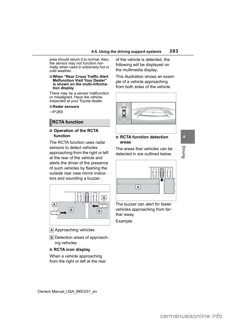
■Operation of the RCTA
function
The RCTA function uses radar
sensors to detect vehicles
approaching from the right or left
at the rear of the vehicle and
alerts the driver of the presence
of such vehicles by flashing the
outside rear view mirror indica-
tors and sounding a buzzer.
Approaching vehicles
Detection areas of approach-
ing vehicles
■RCTA icon display
When a vehicle approaching
from the right or left at the rear of the vehicle is detected, the
following will be displayed on
the multimedia display.
This illustration shows an exam-
ple of a vehicle approaching
from both sides of the vehicle.
■RCTA function detection
areas
The areas that vehicles can be
detected in are outlined below.
The buzzer can alert for faster
vehicles approaching from far-
ther away.
Example:
RCTA function