2022 TOYOTA TUNDRA HYBRID light
[x] Cancel search: lightPage 57 of 618
571-2. Child safety
Owners Manual_USA_M0C031_en
1
For safety and security
WARNING
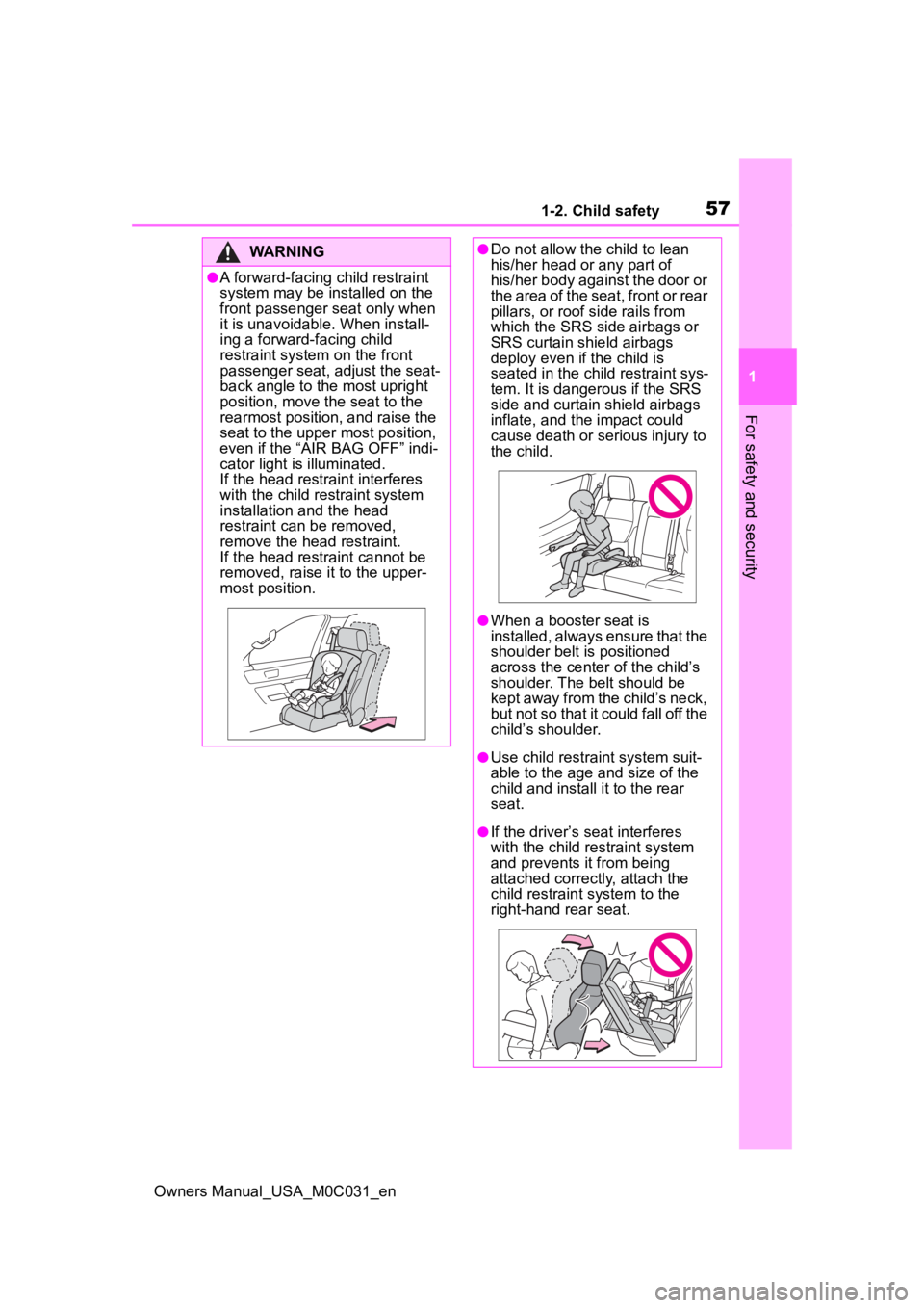
●A forward-facing child restraint
system may be installed on the
front passenger seat only when
it is unavoidable. When install-
ing a forward-facing child
restraint system on the front
passenger seat, adjust the seat-
back angle to the most upright
position, move the seat to the
rearmost position, and raise the
seat to the upper most position,
even if the “AIR BAG OFF” indi-
cator light is illuminated.
If the head restraint interferes
with the child restraint system
installation and the head
restraint can be removed,
remove the head restraint.
If the head restraint cannot be
removed, raise i t to the upper-
most position.
●Do not allow th e child to lean
his/her head or any part of
his/her body against the door or
the area of the seat, front or rear
pillars, or roof side rails from
which the SRS side airbags or
SRS curtain shield airbags
deploy even if the child is
seated in the child restraint sys-
tem. It is dangerous if the SRS
side and curtain shield airbags
inflate, and the impact could
cause death or serious injury to
the child.
●When a booster seat is
installed, always ensure that the
shoulder belt is positioned
across the center of the child’s
shoulder. The belt should be
kept away from the child’s neck,
but not so that it could fall off the
child’s shoulder.
●Use child restrai nt system suit-
able to the age and size of the
child and install it to the rear
seat.
●If the driver’s seat interferes
with the child restraint system
and prevents it from being
attached correct ly, attach the
child restraint system to the
right-hand rear seat.
Page 58 of 618
581-2. Child safety
Owners Manual_USA_M0C031_en
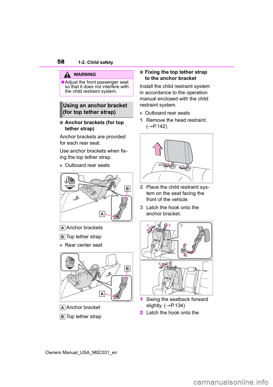
■Anchor brackets (for top
tether strap)
Anchor brackets are provided
for each rear seat.
Use anchor brackets when fix-
ing the top tether strap.
Outboard rear seats
Anchor brackets
Top tether strap
Rear center seatAnchor bracket
Top tether strap
■Fixing the top tether strap
to the anchor bracket
Install the child restraint system
in accordance to the operation
manual enclosed with the child
restraint system.
Outboard rear seats
1 Remove the head restraint.
( P.142)
2 Place the child restraint sys-
tem on the seat facing the
front of the vehicle.
3 Latch the hook onto the
anchor bracket.
1 Swing the seatback forward
slightly. ( P.134)
2 Latch the hook onto the
WARNING
●Adjust the front passenger seat
so that it does no t interfere with
the child restraint system.
Using an anchor bracket
(for top tether strap)
Page 59 of 618
591-2. Child safety
Owners Manual_USA_M0C031_en
1
For safety and security
anchor bracket.
3 Fix the top tether strap so
that there is no slack.
4 Return the seatback.
4 Secure the child restraint
system using the seat belt
( P.63) or the lower anchors
( P.60), and then tighten the
top tether strap.
Make sure the top tether strap is
securely latched.
5 If the head restraint does not
interfere with the child
restraint system installation,
install the head restraint.
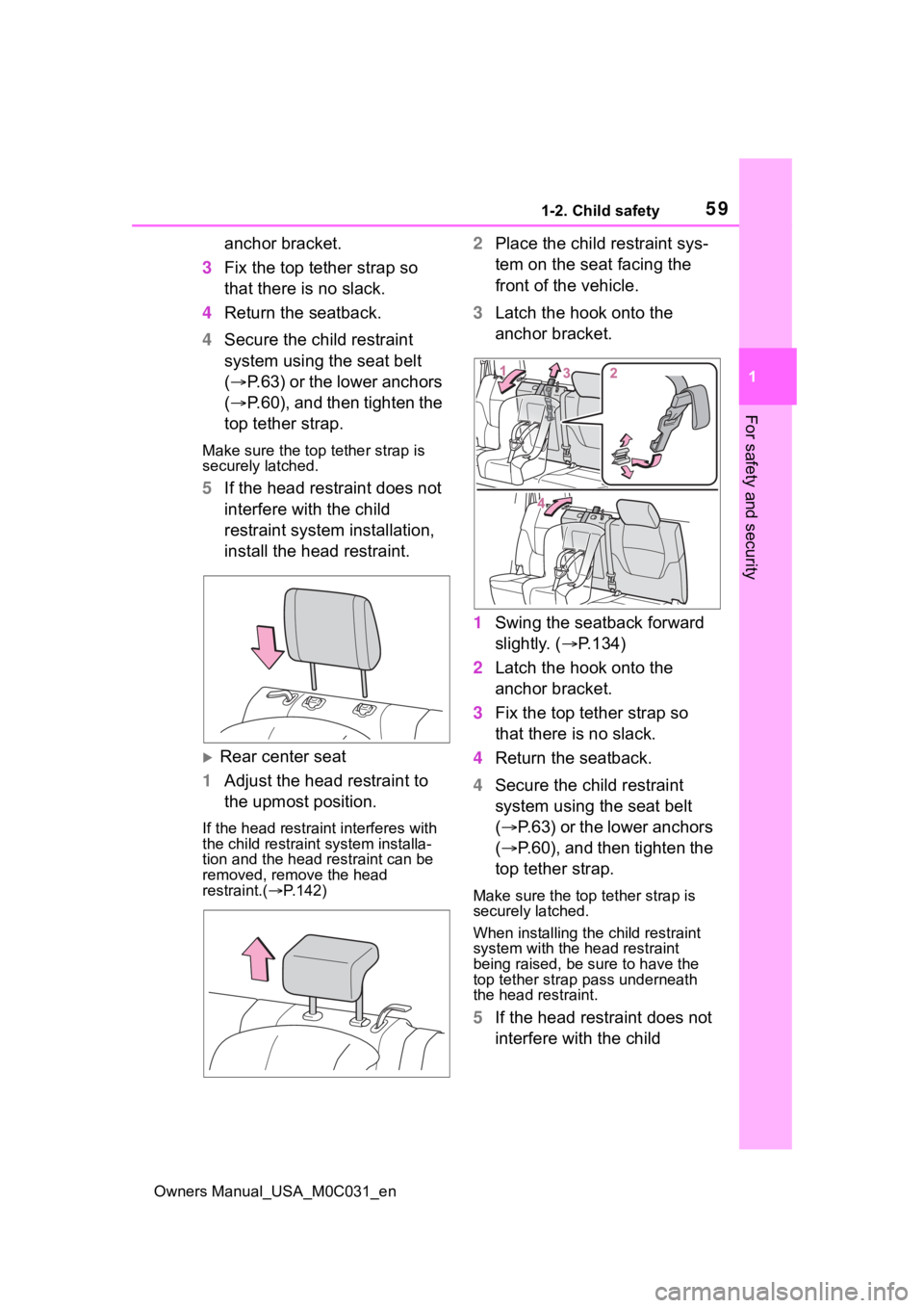
Rear center seat
1 Adjust the head restraint to
the upmost position.
If the head restraint interferes with
the child restraint system installa-
tion and the head restraint can be
removed, remove the head
restraint.( P.142)
2 Place the child restraint sys-
tem on the seat facing the
front of the vehicle.
3 Latch the hook onto the
anchor bracket.
1 Swing the seatback forward
slightly. ( P.134)
2 Latch the hook onto the
anchor bracket.
3 Fix the top tether strap so
that there is no slack.
4 Return the seatback.
4 Secure the child restraint
system using the seat belt
( P.63) or the lower anchors
( P.60), and then tighten the
top tether strap.
Make sure the top tether strap is
securely latched.
When installing the child restraint
system with the head restraint
being raised, be sure to have the
top tether strap pass underneath
the head restraint.
5 If the head restraint does not
interfere with the child
Page 61 of 618
611-2. Child safety
Owners Manual_USA_M0C031_en
1
For safety and security
remove the head restraint.
( P.142)
2 Widen the gap between the
seat cushion and seatback
slightly.
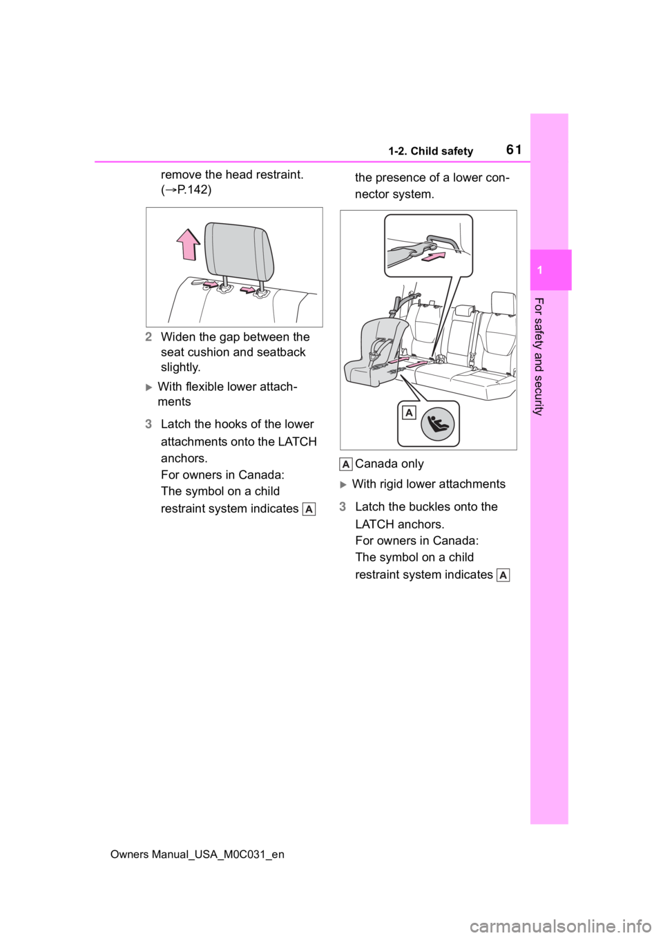
With flexible lower attach-
ments
3 Latch the hooks of the lower
attachments onto the LATCH
anchors.
For owners in Canada:
The symbol on a child
restraint system indicates the presence of a lower con-
nector system.
Canada only
With rigid lower attachments
3 Latch the buckles onto the
LATCH anchors.
For owners in Canada:
The symbol on a child
restraint system indicates
Page 68 of 618

681-3. Emergency assistance
Owners Manual_USA_M0C031_en
1-3.Emergency assistance
*: If equipped
Microphone
“SOS” button
LED light indicators
Speaker
■Certification
P.610
Subscribers have the following
Safety Connect services avail-
able:
Automatic Collision Notifica-
tion
*
Helps drivers receive necessary
response from emergency service
providers. ( P. 7 0 )
*: U.S. Patent No. 7,508,298 B2
Stolen Vehicle Location
Helps drivers in the event of vehicle
theft. ( P. 7 0 )
Emergency Assistance Button
Safety Connect*
Safety Connect is a sub-
scription-based telematics
service that uses Global
Positioning System (GPS)
data and embedded cellular
technology to provide
safety and security fea-
tures to subscribers. Safety
Connect is supported by
Toyota’s designated
response center, which
operates 24 hours per day, 7
days per week.
Safety Connect service is
available by subscription on
select, telematics hardware-
equipped vehicles.
By using the Safety Con-
nect service, you are agree-
ing to be bound by the
Telematics Subscription
Service Agreement and its
Terms and Conditions, as in
effect and amended from
time to time, a current copy
of which is available at Toy-
ota.com. All use of the
Safety Connect service is
subject to such then-appli-
cable Terms and Condi-
tions.
System components
Services
Page 70 of 618

701-3. Emergency assistance
Owners Manual_USA_M0C031_en
When the power switch is turned
to ON, the red indicator light
comes on for 2 seconds then
turns off. Afterward, the green
indicator light comes on, indicat-
ing that the service is active.
The following indicator light pat-
terns indicate specific system
usage conditions:
Green indicator light on =
Active service
Green indicator light flashing
= Safety Connect call in pro-
cess
Red indicator light (except at
vehicle start-up) = System
malfunction (contact your Toy-
ota dealer)
No indicator light (off) =
Safety Connect service not
active
■Automatic Collision Notifi-
cation
In case of either airbag deploy-
ment or severe rear-end colli-
sion, the system is designed to
automatically call the response
center. The responding agent
receives the vehicle’s location
and attempts to speak with the
vehicle occupants to assess the
level of emergency. If the occu- pants are unable to communi-
cate, the agent automatically
treats the call as an emergency,
contacts the nearest emer-
gency services provider to
describe the situation, and
requests that assistance be sent
to the location.
■Stolen Vehicle Location
If your vehicle is stolen, Safety
Connect can work with local
authorities to assist them in
locating and recovering the
vehicle. After filing a police
report, call the Safety Connect
response center at 1-800-331-
4331 in the United States, 1-
877-855-8377 in Puerto Rico or
1-888-869-6828 in Canada, and
follow the prompts for Safety
Connect to initiate this service.
In addition to assisting law
enforcement with recovery of a
stolen vehicle, Safety-Connect-
equipped vehicle location data
may, under certain circum-
stances, be shared with third
parties to locate your vehicle.
Further information is available
at Toyota.com.
■Emergency Assistance But-
ton (“SOS”)
In the event of an emergency on
the road, push the “SOS” button
to reach the Safety Connect
response center. The answer-
ing agent will determine your
vehicle’s location, assess the
emergency, and dispatch the
Safety Connect LED light
Indicators
Safety Connect services
Page 77 of 618
771-4. Hybrid system
Owners Manual_USA_M0C031_en
1
For safety and security
■Running out of fuel
When the vehicle has run out of fuel
and the hybrid system cannot be
started, refuel th e vehicle with at
least enough gasoline to make the
low fuel level warning light ( P.507)
go off. If there is only a small
amount of fuel, th e hybrid system
may not be able to start. (The stan-
dard amount of fuel is about 21.9 L
[5.8 gal., 4.8 Imp. gal.] when the
vehicle is on a level surface. This
value may vary whe n the vehicle is
on a slope. Add extra fuel when the
vehicle is inclined.)
■Electromagnetic waves
●High voltage parts and cables on
Hybrid Electric Vehicles incorpo-
rate electromagnetic shielding,
and therefore emi t approximately
the same amount of electromag-
netic waves as conventional gaso-
line powered vehicles or home
electronic appliances.
●Your vehicle may cause sound
interference in so me third party-
produced radio parts.
■Hybrid battery (tr action battery)
The hybrid battery (traction battery)
has a limited service life. The lifes-
pan of the hybrid battery (traction
battery) can change in accordance
with driving style and driving condi-
tions.
■Starting the hybrid system in an
extremely cold environment
When the hybrid battery (traction
battery) is extremely cold (below
approximately -31°F [-35°C]) under
the influence of t he outside tem-
perature, it may no t be possible to
start the hybrid system. In this case,
try to start the hybrid system again
after the temperature of the hybrid
battery increases due to the outside
temperature increase etc.
WARNING
■High voltage precautions
This vehicle has high voltage DC
and AC systems as well as a 12-
volt system. DC and AC high volt-
age is very dangerous and can
cause severe burns and electric
shock that may result in death or
serious injury.
●Never touch, disassemble,
remove or replace the high volt-
age parts, cables or their con-
nectors.
●The hybrid system will become
hot after starting as the system
uses high voltage. Be careful of
both the high voltage and the
high temperature, and always
obey the warning labels
attached to the vehicle.
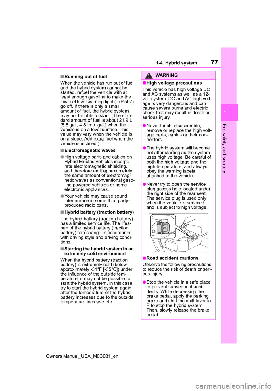
●Never try to open the service
plug access hole located under
the right side o f the rear seat.
The service plug is used only
when the vehicle is serviced
and is subject to high voltage.
■Road accident cautions
Observe the following precautions
to reduce the risk of death or seri-
ous injury:
●Stop the vehicle in a safe place
to prevent subsequent acci-
dents. While depressing the
brake pedal, apply the parking
brake and shift the shift lever to
P to stop the hybrid system.
Then, slowly release the brake
pedal
Page 80 of 618
801-4. Hybrid system
Owners Manual_USA_M0C031_en
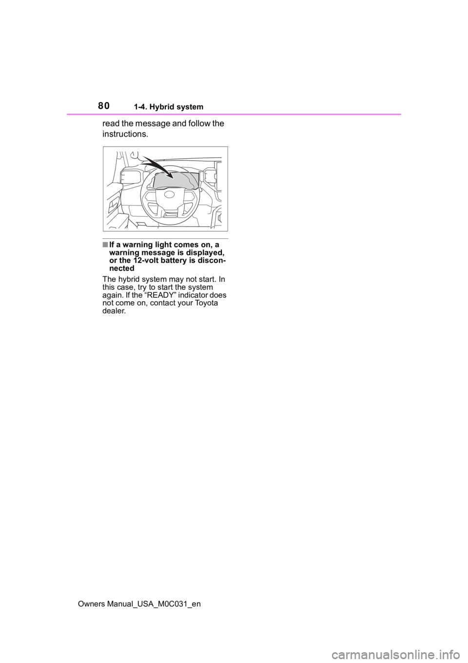
read the message and follow the
instructions.
■If a warning light comes on, a
warning message is displayed,
or the 12-volt battery is discon-
nected
The hybrid system may not start. In
this case, try to start the system
again. If the “READY” indicator does
not come on, contact your Toyota
dealer.