2022 TOYOTA SUPRA engine
[x] Cancel search: enginePage 265 of 498

263
3
3-1. CONTROLS
CONTROLS
The cooling function is switched on
when the engine is running.
The cooling function is switched on
automatically during recirculated-air
mode to dry the air and prevent
condensation.
Depending on the weather condi-
tions, the windscreen and side win-
dows may mist over for a short time
when the drive-ready state has
been switched on.
The cooling function is switched on
automatically in the AUTO pro-
gramme.
When the automatic air condition-
ing is in operation, condensation
develops and exits underneath the
vehicle.
When drive-ready state is switched
on, the system is set to lowest tem-
perature, optimum air flow and
recirculated-air mode.
The function is available at an out-
side temperature above approxi-
mately 0°C/32°F and when
drive-ready state is switched on.
The LED is illuminated when the
system is switched on.
The air flows from the side nozzles
for the upper body area. Therefore
open the side nozzles.
The air flow can be adapted when
the programme is active.
The AUTO programme cools, venti-
lates or heats the interior automati-
cally.
It does this by automatically regu-
lating the air flow, air distribution
and temperature depending on the
interior temperature and the
selected temperature setting.
The LED is illuminated when the
AUTO programme is switched on.
Depending on the selected temper-
ature and external influences, the
air is directed towards the wind-
screen, the side windows the upper
Switching on/off
Press the button.
Maximum cooling effect
Principle
General
Switching on/off
Press the button.
AUTO programme
Principle
Switching on/off
Press the button.
Page 267 of 498
265
3
3-1. CONTROLS
CONTROLS
In order to protect the battery the
air flow rate of the automatic air
conditioning is reduced, if neces-
sary.
The air distribution for air condition-
ing can be set manually.
Windows, upper body area and
footwell.
Upper body area and footwell.
Footwell.
Windows and footwell.
Windows.
Windows and upper body.
Upper body area.
The selected air distribution is
shown on the display for automatic
air conditioning.
If there is condensation, remove it,
see page 265.
Ice and condensation are quickly
removed from the windscreen and
the front side windows.
The LED is illuminated when the
system is switched on.
The air flow can be adjusted manu-
ally when the system is switched
on.
The function is available when the
engine is running.
The rear window heating is
switched off automatically after a
certain period of time.
To adjust the air distribution
manually
Principle
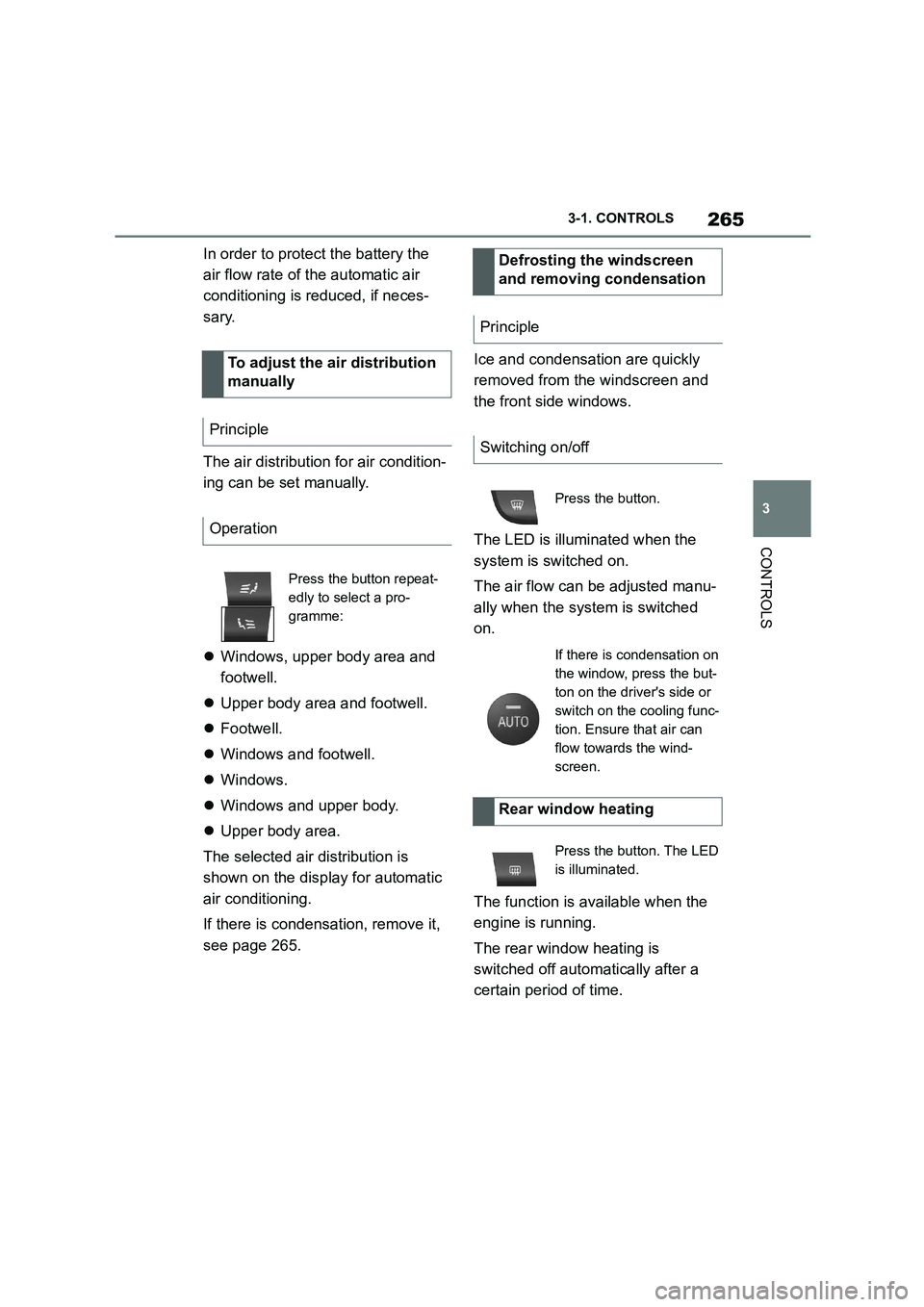
Operation
Press the button repeat-
edly to select a pro-
gramme:
Defrosting the windscreen
and removing condensation
Principle
Switching on/off
Press the button.
If there is condensation on
the window, press the but-
ton on the driver's side or
switch on the cooling func-
tion. Ensure that air can
flow towards the wind-
screen.
Rear window heating
Press the button. The LED
is illuminated.
Page 269 of 498

267
3
3-1. CONTROLS
CONTROLS
The independent ventilation allows
the temperature of the interior to be
adjusted before the journey starts.
Depending on the set temperature
and ambient temperature, the inte-
rior is ventilated or heated using
any available residual heat from the
engine.
The system can be switched on
and off directly or for a preselected
departure time.
The switch-on time is calculated
based on the outside temperature.
The system will switch on in good
time before the preselected depar-
ture time.
Vehicle is in rest or standby state
and not in drive-ready state.
Battery is sufficiently charged.
When activated, the independent venti-
lation uses power from the vehicle bat-
tery. As a result, the maximum
activation time is restricted to protect
the battery. After the engine is started
or after driving a short distance, the
system will be av ailable again.
Ensure that the date and time
are set correctly in the vehicle.
Open the vents to allow the air to
enter the passenger compart-
ment.
The system can be switched on or
off in various ways.
The system switches off automati-
cally after a certain period of time. It
continues to run for a short time
after it has been switched off.
■General
If the vehicle is in standby state, the
independent ventilation can be
switched on or off via the buttons of
the automatic air conditioning.
■Switching on
Press any button, except:
Rear window heating.
Lower side of air flow button.
Seat heating.
■Switching off
The system switches off after leav-
ing and locking the vehicle.
Press and hold the down
button.
1 "My Vehicle"
2 "Vehicle settings"
Independent ventilation
Principle
General
Operating requirements
Switching on/off directly
General
Using the button
Via Toyota Supra Command
Page 270 of 498
2683-1. CONTROLS
3"Climate comfort"
4 "Auxiliary ventilation"
5 "Activate now"
symbol on the automatic air con-
ditioning signals that the system is
switched on.
REST is shown on the air condition-
ing system. The residual heat of the
engine is being used.
To ensure a pleasant interior tem-
perature in the vehicle at the start
of the journey, it is possible to set
different departure times.
One-off departure time: the time
can be set.
System is switched on once.
Departure time with day of the
week: time and day of the week
can be set.
The system is switched on in good time
before the set departure time on the
required days of the week.
Departure time pre-selection is
done in two stages:
Set departure times.
Activate departure time.
At least 10 minutes should pass
between adjusting/ activating the
departure time and the scheduled
departure time, so the climate con-
trol has enough time to work.
■Via Toyota Supra Command
1 "My vehicle"
2 "Vehicle settings"
3 "Climate comfort"
4 "Auxiliary ventilation"
5 Select the required departure
time.
6 Set the departure time.
7 Select the day of the week if
necessary.
■Operating requirements
If a departure time is to control
when the independent ventilation is
switched on, the relevant depar-
ture time must be activated first.
■Via Toyota Supra Command
1 "My vehicle"
2 "Vehicle settings"
3 "Climate comfort"
4 "Auxiliary ventilation"
5 "For departure time"
6 Activate the required departure
time.
Symbol on the automatic air con-
ditioning system signals that a
Display
Departure time
Principle
Setting the departure time
Activating the departure time
Display
Page 272 of 498
2703-1. CONTROLS
cal devices when standby state or
drive-ready state is switched on.
The total load of all sockets must
not exceed 140 watts at 12 volts.
To avoid damage to the socket, do
not insert an incompatible plug.
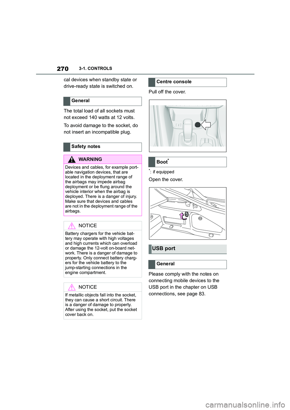
Pull off the cover.
*: if equipped
Open the cover.
Please comply with the notes on
connecting mobile devices to the
USB port in the chapter on USB
connections, see page 83.
General
Safety notes
WA R N I N G
Devices and cables, for example port-
able navigation devices, that are located in the deployment range of
the airbags may impede airbag
deployment or be flung around the vehicle interior when the airbag is
deployed. There is a danger of injury.
Make sure that devices and cables are not in the deployment range of the
airbags.
NOTICE
Battery chargers for the vehicle bat- tery may operate with high voltages
and high currents which can overload
or damage the 12-volt on-board net- work. There is a danger of damage to
property. Only connect battery charg-
ers for the vehicle battery to the jump-starting connections in the
engine compartment.
NOTICE
If metallic objects fall into the socket,
they can cause a short circuit. There
is a danger of damage to property.
After using the socket, put the socket cover back on.
Centre console
Boot*
USB port
General
Page 282 of 498
2804-1. DRIVING HINTS
4-1.DRIVING HINTS
This chapter describes all standard,
country-specific and special equip-
ment available for the model series.
It may therefore describe equip-
ment and functions which are not
installed in your vehicle, for exam-
ple on account of the special equip-
ment selected or the country
specification. This also applies to
safety-relevant functions and sys-
tems. Please comply with the rele-
vant laws and regulations when
using the corresponding functions
and systems.
Moving parts must adapt to one
another.
The following notes will help to
maximise the vehicle's lifetime and
efficiency.
Do not use Launch Control, see
page 159, when running in.
Do not exceed the maximum
engine revs and speed:
With petrol engines, 4500 rpm
and 160 km/h, approximately
100 mph.
Generally avoid kick-down and driv-
ing under full load.
Engine and road speeds can be
gradually increased.
Due to the manufacturing process,
new tyres do not provide maximum
grip immediately.
Drive moderately for the first 300
km, 200 miles.
Driving precautions
Vehicle equipment
Running in
General
Safety note
WA R N I N G
New parts and components can
cause safety and Driver Assistance Systems to respond with a delay.
There is a danger of accidents. After
new parts have been installed or if the vehicle is new, drive moderately and
intervene at an early stage if neces-
sary. Please comply with running-in
procedures for the corresponding parts and components.
Engine, gearbox and differ-
ential
Up to 2000 km, 1200 miles
From 2000 km, 1200 miles
onwards
Ty r e s
Page 284 of 498
2824-1. DRIVING HINTS
temperatures to clean the exhaust
gas particle filter as necessary.
The cleaning process takes a few
minutes, during which the following
may occur:
Engine temporarily runs a bit
roughly.
A slightly higher engine speed is
required to achieve the usual
power output.
A small amount of smoke from
the exhaust, even after stopping
the engine.
Noise, for example from radiator
fan operation, may be heard,
even some minutes after stop-
ping the engine.
It is normal for the radiator fan to
keep running for several minutes,
even after short trips.
The self-cleaning function of the
exhaust particle filter is an auto-
matic process that is supported by
different measures, for example
additional heating.
General
Cleaning the exhaust gas
particle filter while driving
Radio signals
WA R N I N G
Certain vehicle functions may be
affected by interference from high-fre- quency radio signals. Such signals
are output from a series of transmis-
sion systems, for example from air traffic beacons or relay stations for
mobile telecommunications.
We recommend you consult any
authorized Toyota retailer or Toyota authorized repairer, or any reliable
repairer should you experience any
difficulties in this regard.
Mobile communication in the
vehicle
WA R N I N G
There is a possibility of reciprocal
interference between the vehicle elec- tronics and mobile radio devices.
Radiation is generated when mobile
radio devices are transmitting. There
is a danger of injury or damage to property. If possible, only use mobile
radio devices, for example mobile
telephones, in the interior if they are connected directly to an external
antenna in order to eliminate recipro-
cal interference and to dissipate the radiation from vehicle's interior.
Page 286 of 498
2844-1. DRIVING HINTS
This situation, known as aquaplan-
ing, means that the tyre can actu-
ally lose contact completely with
the road surface and the vehicle
can neither be steered, nor the
brakes properly applied.
Please comply with the following
when driving through water:
Deactivate the Automatic
Start/Stop function.
Only drive through still water.
Only drive through water up to a
max. depth of 25 cm, 9.8 in.
Drive through water at a walking
speed of no more than 5 km/h, 3
mph.
The vehicle is equipped with the
Anti-lock Brake System ABS as
standard.
Perform full brakin g in situations
that require it.
The vehicle remains steerable. Any
obstacles can be avoided by steer-
ing as smoothly as possible.
A pulsing of the brake pedal and
hydraulic regulating sounds indi-
cate that the anti-lock brake system
ABS is functioning.
In certain braking situations, the
perforated brake discs can cause
functional noise. However, func-
tional noises have no effect on the
efficiency and operational safety of
the brakes.
In wet weather, on gritted roads and
in heavy rain, apply the brakes
lightly every few kilometres/miles.
Driving through water
General
Safety note
NOTICE
Driving through excessively deep water too fast can result in water
entering the engine compartment,
electrical system or transmission. There is a danger of damage to prop-
erty. When driving through water, do
not exceed the maximum water depth and speed specified above.
Safe braking
General
Objects in the range of movement
of the pedals
WA R N I N G
Objects in the driver's footwell can
restrict the pedal travel or block a
pedal that has been pressed. There is a risk of accident. Ensure that items in
the vehicle are stowed securely and
cannot get into the driver's footwell. Only use floor mats that are suitable
for the vehicle and can be securely
fastened to the floor. Do not use loose floor mats, and do not place several
floor mats on top of one another.
Make sure that there is sufficient space for the pedals. Ensure that floor
mats are securely reattached after
removal, for example for cleaning.
Wet roads