2022 TOYOTA GR SUPRA weight
[x] Cancel search: weightPage 97 of 356

973-1. CONTROLS
3
CONTROLS
1Backrest angle
2 Height
3 Backrest width*
4 Lumbar support*
5 Forward/back
6 Seat angle*
*: if equipped
Pull the lever and apply your
weight to or lift your weight off
the backrest as required. Pull the lever up or press the
lever down repeatedly until the
seat reaches the desired height.
Pull the lever and slide the seat
in the desired direction.
After releasing the lever, move
the seat gently forward or back
to make sure it engages prop-
erly.
Manually adjustable seats
Overview
Backrest angle
654321
Height
Forward/back
Page 110 of 356
1103-1. CONTROLS
WARNING
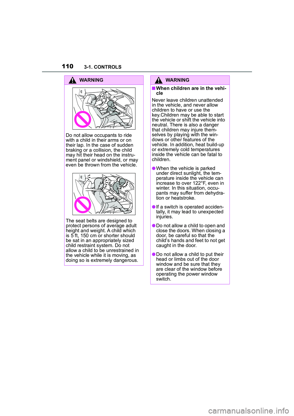
Do not allow occupants to ride
with a child in their arms or on
their lap. In the case of sudden
braking or a collision, the child
may hit their head on the instru-
ment panel or windshield, or may
even be thrown from the vehicle.
The seat belts are designed to
protect persons of average adult
height and weight. A child which
is 5 ft, 150 cm or shorter should
be sat in an appropriately sized
child restraint system. Do not
allow a child to be unrestrained in
the vehicle while it is moving, as
doing so is extremely dangerous.
WARNING
■When children are in the vehi-
cle
Never leave children unattended
in the vehicle, and never allow
children to have or use the
key.Children may be able to start
the vehicle or shift the vehicle into
neutral. There is also a danger
that children ma y injure them-
selves by playing with the win-
dows or other features of the
vehicle. In addition, heat build-up
or extremely cold temperatures
inside the vehicle can be fatal to
children.
●When the vehicle is parked
under direct sunlight, the tem-
perature inside the vehicle can
increase to over 122°F, even in
winter. In this situation, occu-
pants may suffer from dehydra-
tion or heatstroke.
●If a switch is operated acciden-
tally, it may lead to unexpected
injuries.
●Do not allow a child to open and
close the doors. When closing a
door, be careful so that the
child’s hands and feet to not get
caught in the door.
●Do not allow a child to put their
head or limbs out of the door
window and be sure that they
are clear of the window before
operating the power window
switch.
Page 245 of 356
2453-1. CONTROLS
3
CONTROLS
The glove compartment can be
locked with an integrated key,
refer to page 83. This prevents
access to the glove compart-
ment.
After the glove compartment is
locked, the remote control can
be handed over without the inte-
grated key, for instance when
the vehicle is parked by valet
parking.
There are storage compart-
ments in the doors.Locking
Compartments in the
doors
General information
Safety information
WARNING
Breakable objects, such as glass
bottles or glasses, can break in
the event of an accident or a brak-
ing or evasive maneuver. Broken
glass can be scattered in the car's
interior. There is a risk of injury or
risk of damage to property. Do not
use any breakable objects while
driving. Only stow breakable
objects in closed storage com-
partments.
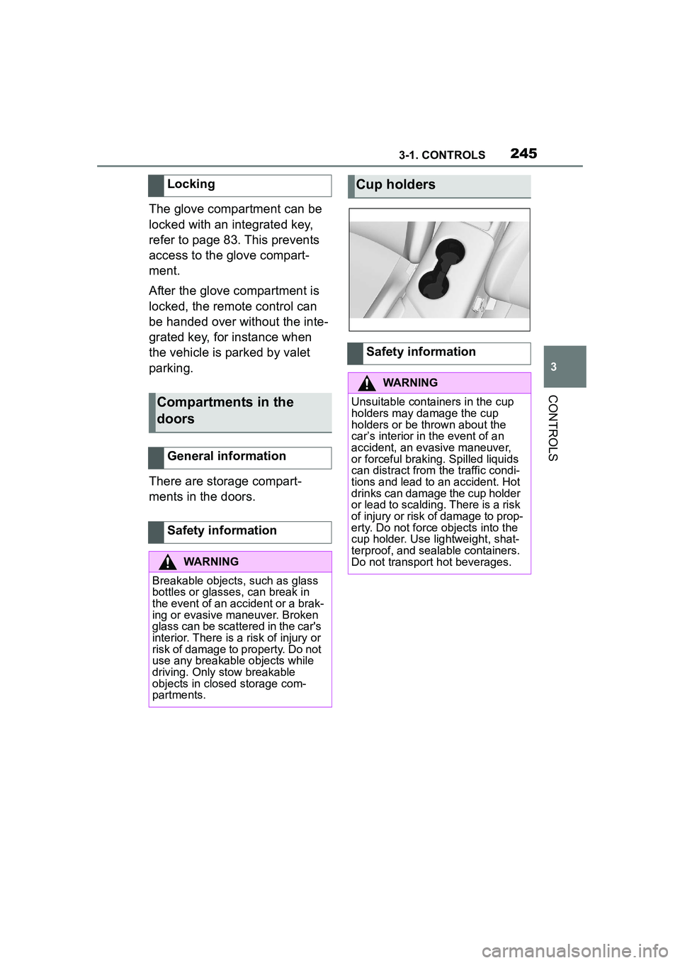
Cup holders
Safety information
WARNING
Unsuitable containers in the cup
holders may damage the cup
holders or be thrown about the
car’s interior in the event of an
accident, an evasive maneuver,
or forceful braking. Spilled liquids
can distract from the traffic condi-
tions and lead to an accident. Hot
drinks can damage the cup holder
or lead to scalding. There is a risk
of injury or risk of damage to prop-
erty. Do not force objects into the
cup holder. Use lightweight, shat-
terproof, and sealable containers.
Do not transport hot beverages.
Page 246 of 356
2463-1. CONTROLS
This chapter describes all stan-
dard, country-specific and
optional features offered with
the series. It also describes fea-
tures and functions that are not
necessarily available in your
vehicle, e.g., due to the selected
options or country versions. This
also applies to safety-related
functions and systems. When
using these functions and sys-
tems, the applicable laws and
regulations must be observed.1Locate the statement “The
combined weight of occu-
pants and cargo should
never exceed XXX kg or XXX
lbs” on your vehicle’s plac-
ard.
2 Determine the combined
weight of the driver and pas-
sengers that will be riding in
your vehicle.
Cargo area
Vehicle features and
options
Loading
Safety information
WARNING
High gross weight can overheat
the tires, damage them internally
and cause a sudden drop in tire
inflation pressure. Driving charac-
teristics may be negatively
impacted, reducing lane stability,
lengthening the braking distances
and changing the steering
response. There is a risk of an
accident. Pay attention to the per-
mitted load capacity of the tires
and never exceed the permitted
gross weight.
WARNING
Loose object or devices with a
cable connection to the vehicle,
for instance mobile phones, can
be thrown about the car’s interior
while driving, for instance in the
event of an accident or during
braking and evasive maneuvers.
There is a risk of injury. Secure
loose objects or devices with a
cable connection to the vehicle in
the car’s interior.
WARNING
Improperly stowed objects can
shift and be thrown into the car’s
interior, for instance in the event
of an accident or during braking
and evasive maneuver. Vehicle
occupants can be hit and injured.
There is a risk of injury. Stow and
secure objects and cargo prop-
erly.
NOTICE
Fluids in the cargo area can
cause damage. There is a risk of
damage to property. Make sure
that no fluids leak in the cargo
area.
Steps for Determining Cor-
rect Load Limit
Page 247 of 356
2473-1. CONTROLS
3
CONTROLS
3Subtract the combined
weight of the driver and pas-
sengers from XXX kg or XXX
lbs.
4 The resulting figure equals
the available amount of cargo
and luggage load capacity.
For example, if the “XXX”
amount equals 1,400 lbs and
there will be five 150 lbs pas-
sengers in your vehicle, the
amount of available cargo
and luggage load capacity is
650 lbs (1,400–750 (5 x 150)
= 650 lbs).
5 Determine the combined
weight of luggage and cargo
being loaded on the vehicle.
That weight may not safely
exceed the available cargo
and luggage load capacity
calculated in Step 4.
6 If your vehicle will be towing
a trailer, load from your trailer
will be transferred to your
vehicle. Consult this manual
to determine how this
reduces the available cargo
and luggage load capacity of
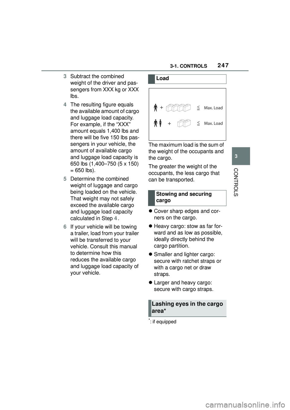
your vehicle. The maximum load is the sum of
the weight of the occupants and
the cargo.
The greater the weight of the
occupants, the less cargo that
can be transported.
Cover sharp edges and cor-
ners on the cargo.
Heavy cargo: stow as far for-
ward and as low as possible,
ideally directly behind the
cargo partition.
Smaller and lighter cargo:
secure with ratchet straps or
with a cargo net or draw
straps.
Larger and heavy cargo:
secure with cargo straps.
*: if equipped
Load
Stowing and securing
cargo
Lashing eyes in the cargo
area*
Page 248 of 356
2483-1. CONTROLS
Attach load securing aids, such
as lashing straps, tensioning
straps, draw straps or cargo
nets, to the lashing eyes in the
cargo area.
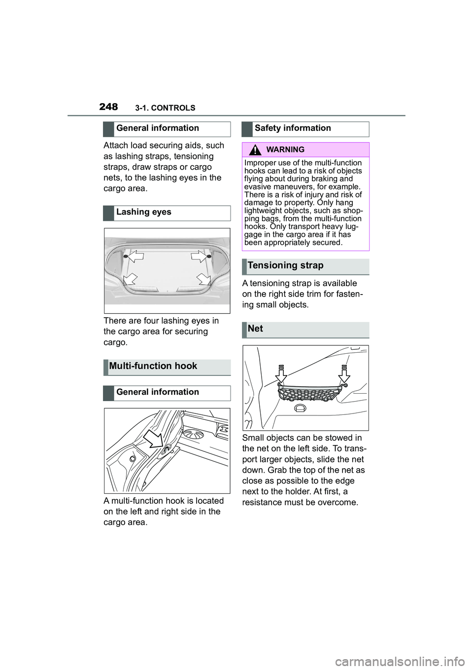
There are four lashing eyes in
the cargo area for securing
cargo.
A multi-function hook is located
on the left and right side in the
cargo area.A tensioning strap is available
on the right side trim for fasten-
ing small objects.
Small objects can be stowed in
the net on the left side. To trans-
port larger objects, slide the net
down. Grab the top of the net as
close as possible to the edge
next to the holder. At first, a
resistance must be overcome.
General information
Lashing eyes
Multi-function hook
General information
Safety information
WARNING
Improper use of the multi-function
hooks can lead to a risk of objects
flying about during braking and
evasive maneuvers, for example.
There is a risk of injury and risk of
damage to property. Only hang
lightweight objects, such as shop-
ping bags, from the multi-function
hooks. Only transport heavy lug-
gage in the cargo area if it has
been appropriately secured.
Tensioning strap
Net
Page 258 of 356
2584-1. DRIVING TIPS
Additional weight increases fuel
consumption.
Attached parts on the vehicle
impair the aerodynamics and
increase the fuel consumption.
Open windows increase air
resistance and therefore lead to
greater fuel consumption.
Tires can affect consumption in
various ways, for instance tire
size may influence consump-
tion.
Check and, if needed, correct
the tire inflation pressure at least
twice a month and before start-
ing on a long trip.
Low tire inflation pressure
increases rolling resistance and
thus raises fuel consumption
and tire wear.Do not wait for the engine to
warm-up while the vehicle
remains stationary. Start driving
right away, but at moderate
engine speeds.
This is the quickest way of
warming the cold engine up to
operating temperature.
Driving smoothly and proactively
reduces fuel consumption.
Avoid unnecessary acceleration
and braking.
By maintaining a suitable dis-
tance to the vehicle driving
ahead of you.
Driving at low engine speeds
lowers fuel consumption and
reduces wear.
If necessary, observe the vehi-
cle's gear shift indicator, refer to
page 142.
When approaching a red light,
take your foot off the accelerator
and let the vehicle coast to a
halt.
For going downhill take your foot
off the accelerator and let the
Remove unnecessary
cargo
Remove attached parts fol-
lowing use
Closing the windows
Tires
General information
Check the tire inflation pres-
sure regularly
Drive away without delay
Look well ahead when
driving
Avoid high engine speeds
Use coasting conditions
Page 269 of 356
2695-1. MOBILITY
5
MOBILITY
R: radial tire code
18: rim diameter in inches
96: load rating, not for ZR tires
Y: speed rating, before the R on
ZR tires
Maximum tire load is the maxi-
mum permissible weight for
which the tire is approved.
Locate the maximum tire load
on the tire sidewall and the
Gross Axle Weight Rating –
GAWR – on the certification
label on the driver door B-pillar.
Divide the tire load by 1.1. It
must be greater than one-half of
the vehicle’s Gross Axle Weight
Rating – GAWR. Note, front vs.
rear GAWR and tire loads,
respectively.
Q = up to 100 mph/160 km/h
R = up to 106 mph/170 km/h
S = up to 112 mph/180 km/h
T = up to 118 mph/190 km/h
H = up to 131 mph/210 km/h
V = up to 150 mph/240 km/h
W = up to 167 mph/270 km/h
Y = up to 186 mph/300 km/h
DOT code: DOT xxxx xxx 3820xxxx: manufacturer code for the
tire brand
xxx: tire size and tire design
3820: tire age
Tires with DOT codes meet the
guidelines of the U.S. Depart-
ment of Transportation.
Regardless of the tire tread,
replace tires at least every 6
years.
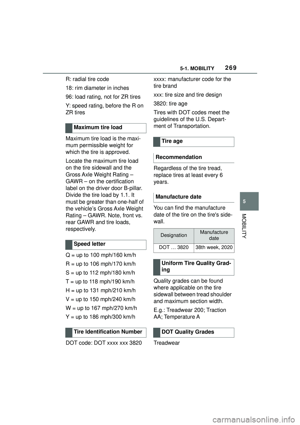
You can find the manufacture
date of the tire on the tire's side-
wall.
Quality grades can be found
where applicable on the tire
sidewall between tread shoulder
and maximum section width.
E.g.: Treadwear 200; Traction
AA; Temperature A
Treadwear
Maximum tire load
Speed letter
Tire Identification Number
Tire age
Recommendation
Manufacture date
DesignationManufacture date
DOT … 382038th week, 2020
Uniform Tire Quality Grad-
ing
DOT Quality Grades