2022 TOYOTA GR SUPRA wheel
[x] Cancel search: wheelPage 212 of 356
2123-1. CONTROLS
Via Toyota Supra Command:
1"My vehicle"
2 "Vehicle settings"
3 "Speed Assistant"
4 "Notes on speed limits" Select the desired setting:
"adjust manually": detected
speed limit can be applied
manually.
"Show current limit": detected
speed limits are displayed in
the instrument cluster without
being applied.
"Off": Speed Limit Assist will
be switched off.
A message is indicated in the
instrument cluster when the sys-
tem and cruise control are acti-
vated.
Safety information
WARNING
The system cannot serve as a
substitute for the driver's personal
judgment in assessing the traffic
situation. Based on the limits of
the system, it cannot inde-
pendently react to all traffic situa-
tions. There is a risk of an
accident. Adjust driving style to
traffic conditions. Watch traffic
closely and actively intervene
where appropriate.
WARNING
The desired speed can be incor-
rectly adjusted or called up by
mistake. There is a risk of an acci-
dent. Adjust the desired speed to
the traffic conditions. Watch traf-
fic closely and actively intervene
where appropriate.
Overview
Buttons on the steering
wheel
ButtonFunction
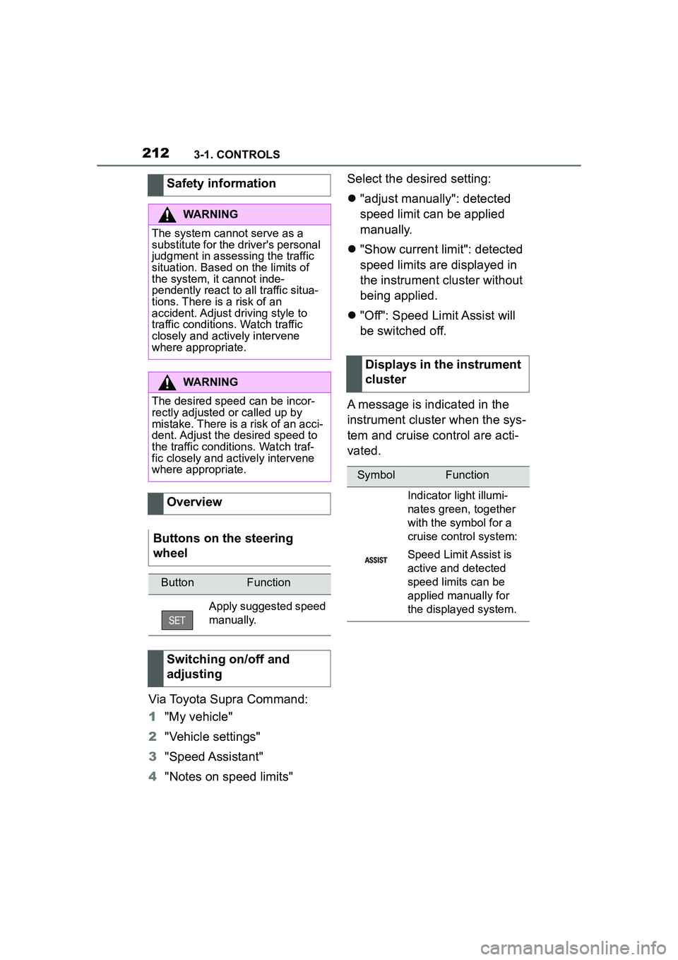
Apply suggested speed
manually.
Switching on/off and
adjusting
Displays in the instrument
cluster
SymbolFunction
Indicator light illumi-
nates green, together
with the symbol for a
cruise control system:
Speed Limit Assist is
active and detected
speed limits can be
applied manually for
the displayed system.
Page 220 of 356

2203-1. CONTROLS
More than one assistance func-
tion can be active at the same
time.
The assistance functions can be
manually activated.
1Move the Controller to the
right, if needed.
2 With corresponding equip-
ment:
3 With corresponding equip-
ment: "Camera image"
"Parking aid lines".
Pathway lines and turning radius
lines are displayed, refer to page
220.
"Obstacle marking".
Depending on the vehicle equip-
ment, the obstacles detected by
Parking Sensors are displayed,
refer to page
221, by markings.
■Pathway lines Pathway lines help you to esti-
mate the space required when
parking and maneuvering on
level roads.
Pathway lines depend on the
steering angle and are continu-
ously adjusted to the steering
wheel movements.
■Turning radius lines
Turning radius lines can only be
superimposed on the camera
image together with pathway
lines.
Turning radius lines show the
course of the smallest possible
turning radius on a level road.
Only one turning radius line is
displayed after the steering
wheel is turned past a certain
angle.
■Parking using pathway and
turning radius lines
1 Position the vehicle so that
the red turning radius line
leads to within the limits of
the parking space.
2 Turn the steering wheel to
the point where the green
pathway line covers the cor-
Display on the Control Dis-
play
General information
Parking aid lines
Page 232 of 356
2323-1. CONTROLS
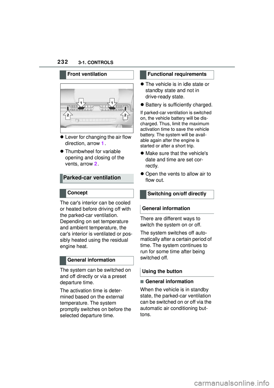
Lever for changing the air flow
direction, arrow 1.
Thumbwheel for variable
opening and closing of the
vents, arrow 2.
The car's interior can be cooled
or heated before driving off with
the parked-car ventilation.
Depending on set temperature
and ambient temperature, the
car's interior is ventilated or pos-
sibly heated using the residual
engine heat.
The system can be switched on
and off directly or via a preset
departure time.
The activation time is deter-
mined based on the external
temperature. The system
promptly switches on before the
selected departure time.
The vehicle is in idle state or
standby state and not in
drive-ready state.
Battery is sufficiently charged.
If parked-car ventilation is switched
on, the vehicle battery will be dis-
charged. Thus, limit the maximum
activation time to save the vehicle
battery. The system will be avail-
able again after the engine is
started or after a short trip.
Make sure that the vehicle's
date and time are set cor-
rectly.
Open the vents to allow air to
flow out.
There are different ways to
switch the system on or off.
The system switches off auto-
matically after a certain period of
time. The system continues to
run for some time after being
switched off.
■General information
When the vehicle is in standby
state, the parked-car ventilation
can be switched on or off via the
automatic air conditioning but-
tons.
Front ventilation
Parked-car ventilation
Concept
General information
Functional requirements
Switching on/off directly
General information
Using the button
Page 254 of 356
2544-1. DRIVING TIPS
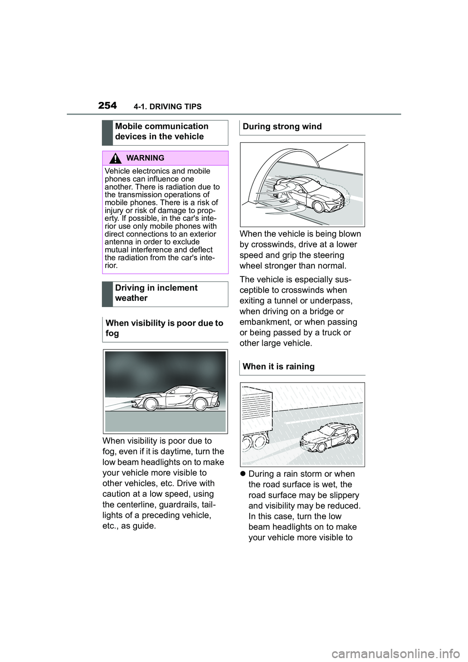
When visibility is poor due to
fog, even if it is daytime, turn the
low beam headlights on to make
your vehicle more visible to
other vehicles, etc. Drive with
caution at a low speed, using
the centerline, guardrails, tail-
lights of a preceding vehicle,
etc., as guide.When the vehicle is being blown
by crosswinds, drive at a lower
speed and grip the steering
wheel stronger than normal.
The vehicle is especially sus-
ceptible to crosswinds when
exiting a tunnel or underpass,
when driving on a bridge or
embankment, or when passing
or being passed by a truck or
other large vehicle.
During a rain storm or when
the road surface is wet, the
road surface may be slippery
and visibility may be reduced.
In this case, turn the low
beam headlights on to make
your vehicle more visible to
Mobile communication
devices in the vehicle
WARNING
Vehicle electronics and mobile
phones can influence one
another. There is radiation due to
the transmission operations of
mobile phones. There is a risk of
injury or risk of damage to prop-
erty. If possible, in the car's inte-
rior use only mobile phones with
direct connections to an exterior
antenna in order to exclude
mutual interference and deflect
the radiation from the car's inte-
r i o r.
Driving in inclement
weather
When visibility is poor due to
fog
During strong wind
When it is raining
Page 261 of 356
261
5
5
MOBILITY
MOBILITY
.5-1. MOBILITYRefueling ..................... 262
Wheels and tires ......... 264
Engine compartment ... 290
Operating materials..... 293
Maintenance ............... 301
Replacing components .................................. 303
Breakdown assistance .................................. 313
Care ............................ 322
Page 264 of 356

2645-1. MOBILITY
This chapter describes all stan-
dard, country-specific and
optional features offered with
the series. It also describes fea-
tures and functions that are not
necessarily available in your
vehicle, e.g., due to the selected
options or country versions. This
also applies to safety-related
functions and systems. When
using these functions and sys-
tems, the applicable laws and
regulations must be observed.
The tire characteristics and tire
inflation pressure influence the
following:
• The service life of the tires.
• Road safety.
• Driving comfort.
• Fuel consumption.The tire inflation pressure table,
refer to page 266, contains all
tire inflation pressure specifica-
tions for the specified tire sizes
at the ambient temperature. The
tire inflation pressure values
apply to tire sizes approved by
the manufacturer of the vehicle
for the vehicle type.
To identify the correct tire infla-
tion pressure, please note the
following:
If the tire's speed code cannot
be found, then the tire inflation
pressure for the corresponding
tire size applies.
• Tire sizes of your vehicle.
• Maximum permitted driving
speed.
Wheels and tires
Vehicle features and
options
Tire inflation pressure
General information
Safety information
WARNING
A tire with too little or no tire infla-
tion pressure may heat up signifi-
cantly and sustain damage. This
will have a negative impact on
aspects of handling, such as
steering and braking response.
There is a risk of an accident.
Regularly check the tire inflation
pressure, and correct it as
needed, for instance twice a
month and before a long trip.
Tire inflation pressure
specifications
In the tire inflation pressure
table
Page 265 of 356

2655-1. MOBILITY
5
MOBILITY
The current tire inflation pres-
sure values and the intended
tire inflation pressure values for
the mounted tires can be dis-
played on the Control Display.
To ensure that they are dis-
played correctly, the tire sizes
must be stored in the system
and must have been set, refer to
page 280, for the mounted tires.
The current tire inflation pres-
sure value is located on each
tire.
The reference tire inflation pres-
sure value is located in the
lower area of the Control Dis-
play.
Tires heat up while driving. The
tire inflation pressure increases
with the tire temperature.
Tires have a natural, consistent
loss of tire inflation pressure.
The displays of inflation devices
may under-read by up to 0.1
bar/2 psi.The tire inflation pressure speci-
fications in the tire inflation pres-
sure table only relate to cold
tires or tires at the same tem-
perature as the ambient tem-
perature.
Only check the tire inflation
pressure levels when the tires
are cold, i.e.:
• Driving range of max. 1.25
miles/2 km has not been
exceeded.
• If the vehicle has not moved again for at least 2 hours after
a trip.
Check the tire inflation pressure
of the emergency wheel in the
cargo area regularly, and correct
it as needed.
1 Determine, refer to page 264,
the intended tire inflation
pressure levels for the
mounted tires.
2 Check the tire inflation pres-
sure in all four tires, using a
pressure gauge, for example.
3 Correct the tire inflation pres-
sure if the actual tire inflation
pressure deviates from spec-
ified tire inflation pressure.
4 Check whether all valve caps
are screwed onto the tire
valves.
On the Control Display
Checking the tire inflation
pressure
General information
Checking using tire inflation
pressure specifications in
the tire inflation pressure
table
Page 270 of 356
2705-1. MOBILITY
Traction AA A B C
Temperature A B C
All passenger vehicle tires must
conform to Federal Safety
Requirements in addition to
these grades
The treadwear grade is a com-
parative rating based on the
wear rate of the tire when tested
under controlled conditions on a
specified government test
course. E.g., a tire graded 150
would wear one and one-half, 1
g, times as well on the govern-
ment course as a tire graded
100. The relative performance
of tires depends upon the actual
conditions of their use, however,
and may depart significantly
from the norm due to variations
in driving habits, service prac-
tices and differences in road
characteristics and climate.
The traction grades, from high-
est to lowest, are AA, A, B, and
C.
Those grades represent the
tire's ability to stop on wet pave-
ment as measured under con-
trolled conditions on specified
government test surfaces of
asphalt and concrete. A tire
marked C may have poor trac-tion performance.
The traction grade assigned to
this tire is based on
straight-ahead braking traction
tests, and does not include
acceleration, cornering, hydro-
planing, or peak traction charac-
teristics.
The temperature grades are A,
the highest, B, and C, represent-
ing the tire's resistance to the
generation of heat and its ability
to dissipate heat when tested
under controlled conditions on a
specified indoor laboratory test
wheel. Sustained high tempera-
ture can cause the material of
the tire to degenerate and
reduce tire life, and excessive
temperature can lead to sudden
tire failure.
The grade C corresponds to a
level of performance which all
passenger vehicle tires must
meet under the Federal Motor
Vehicle Safety Standard No.
109. Grades Band A represent
higher levels of performance on
the laboratory test wheel than
the minimum required by law.
Treadwear
Tr a c t i o n
Temperature