2022 TOYOTA GR SUPRA ESP
[x] Cancel search: ESPPage 221 of 356

2213-1. CONTROLS
3
CONTROLS
responding turning radius
line.
Depending on the vehicle equip-
ment, obstacles behind the vehi-
cle are detected by the Parking
Sensors.
Obstacle markings can be faded
into the image of the rearview
camera.
The colored thresholds of the
obstacle markings match the
markings of the Parking Sen-
sors.
With the rearview camera
switched on:
1 Move the Controller to the
left, if needed.
2 "Camera image"
3
"Brightness"
"Contrast" 4
Set the desired value.
Additional information:
• Cameras, refer to page 40.
If the camera is deactivated, for
instance if the trunk lid is open,
the camera image is displayed
hatched in gray.
Very low obstacles as well as
high, protruding objects such as
ledges may not be detected by
the system.
Depending on the vehicle equip-
ment, some assistance func-
tions also consider data from the
Parking Sensors.
Follow the notes in the Parking
Sensors chapter.
The objects displayed on the
Control Display may be closer
than they appear. Do not esti-
mate the distance from the
objects on the display.
*: if equipped
Obstacle marking
Setting brightness and
contrast via Toyota Supra
Command
System limits
System limits of the sensors
Deactivated camera
Detection of objects
RCTA (Rear cross traffic
alert) function*
Page 223 of 356

2233-1. CONTROLS
3
CONTROLS
1"My vehicle"
2 "Vehicle settings"
3 "Parking"
4 "Cross traffic alert"
5 "Cross traffic alert"
If the system was activated on
the Control Display, it is auto-
matically switched on as soon
as Parking Sensors or Pan-
orama View is active and a gear
is engaged.
If reverse gear is engaged, the
rear system is switched on.
The system is automatically
switched off in the following situ-
ations:
When the speed exceeds
walking speed.
When a certain driving dis-
tance is exceeded.
With an active parking opera-
tion of the parking assistant.
The respective display is called
up on the Control Display. A sig-
nal tone may sound and the light
in the exterior mirror may flash. The light in the exterior mirror
flashes if vehicles are detected
by the rear sensors and your
own vehicle is moving back-
wards.
In the Parking Sensors view, the
respective boundary area
flashes red, if vehicles are
detected by the sensors.
In addition to the optical indica-
tor, a warning signal sounds if
your own vehicle moves into the
respective direction.
Switching on automatically
Switching off automatically
WARNING
General informationLight in the exterior mirror
Display in the Parking Sen-
sors view
Acoustic warning
Page 234 of 356
2343-1. CONTROLS
6Set the departure time.
7 Select day of the week, if
needed.
■Functional requirement
If a departure time is to influ-
ence the switching on of
parked-car ventilation, the
respective departure time must
be activated first.
■Via Toyota Supra Command
1 "My Vehicle"
2 "Vehicle settings"
3 "Climate functions"
4 "Comfort ventilation"
5 "For departure time"
6 Activate the desired depar-
ture time.
The symbol on the automatic
air conditioning signals an acti-
vated departure time. This chapter describes all stan-
dard, country-specific and
optional features offered with
the series. It also describes fea-
tures and functions that are not
necessarily available in your
vehicle, e.g., due to the selected
options or country versions. This
also applies to safety-related
functions and systems. When
using these functions and sys-
tems, the applicable laws and
regulations must be observed.
The integrated Universal
Remote Control in the interior
mirror can operate up to 3 func-
tions of remote-controlled sys-
tems such as garage door
drives, barriers, or lighting sys-
tems.
The Integrated Universal
Remote Control replaces up to 3
different hand-held transmitters.
To operate the remote control,
the buttons on the interior mirror
must be programmed with the
Activating the departure time
Display
Interior equipment
Vehicle features and
options
Integrated Universal
Remote Control
Concept
General information
Page 235 of 356
2353-1. CONTROLS
3
CONTROLS
desired functions. The
hand-held transmitter for the
particular system is required in
order to program the remote
control.
Before selling the vehicle, delete
the stored functions for the sake
of security.
If possible, do not install the
antenna of the remote-con-
trolled system, e.g. the garage
door drive, near metal objects to
ensure the best possible opera-
tion.Additional questions are
answered by:
Your Toyota dealer.
www.homelink.com on the
Internet.
HomeLink is a registered trade-
mark of Gentex Corporation.
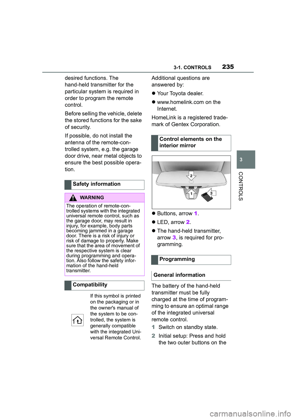
Buttons, arrow 1.
LED, arrow 2.
The hand-held transmitter,
arrow 3, is required for pro-
gramming.
The battery of the hand-held
transmitter must be fully
charged at the time of program-
ming to ensure an optimal range
of the integrated universal
remote control.
1 Switch on standby state.
2 Initial setup: Press and hold
the two outer buttons on the
Safety information
WARNING
The operation of remote-con-
trolled systems with the integrated
universal remote control, such as
the garage door, may result in
injury, for example, body parts
becoming jammed in a garage
door. There is a risk of injury or
risk of damage to property. Make
sure that the area of movement of
the respective system is clear
during programming and opera-
tion. Also follow the safety infor-
mation of the hand-held
transmitter.
Compatibility
If this symbol is printed
on the packaging or in
the owner's manual of
the system to be con-
trolled, the system is
generally compatible
with the integrated Uni-
versal Remote Control.
Control elements on the
interior mirror
Programming
General information
Page 238 of 356
2383-1. CONTROLS
The system, such as the garage
door, can be operated using the
button on the interior mirror
while the drive-ready or standby
state is switched on. To do this,
hold down the button within
receiving range of the system
until the function is activated.
The interior mirror LED stays lit
while the wireless signal is being
transmitted.
All stored functions will be
deleted. The functions cannot
be deleted individually.
Press and hold the two outer
buttons on the interior mirror
simultaneously for approxi-
mately 10 seconds until the LED
on the interior mirror flashes
green rapidly.Fold the sun visor down or up.
A vanity mirror is located in the
sun visor behind a cover. When
the cover is opened, the mirror
lighting switches on.
The lighter socket can be used
as a socket for electrical equip-
ment when standby and
drive-ready state are switched
on.
The total load of all sockets
must not exceed 140 watts at 12
volts.
Do not damage the socket by
using non-compatible connec-
tors.
Operation
WARNING
The operation of remote-con-
trolled systems with the integrated
universal remote control, such as
the garage door, may result in
injury, for example, body parts
becoming jammed in a garage
door. There is a risk of injury or
risk of damage to property. Make
sure that the area of movement of
the respective system is clear
during programming and opera-
tion. Also follow the safety infor-
mation of the hand-held
transmitter.
Deleting stored functions
Sun visor
Glare shield
Vanity mirror
Sockets
Concept
General information
Page 246 of 356
2463-1. CONTROLS
This chapter describes all stan-
dard, country-specific and
optional features offered with
the series. It also describes fea-
tures and functions that are not
necessarily available in your
vehicle, e.g., due to the selected
options or country versions. This
also applies to safety-related
functions and systems. When
using these functions and sys-
tems, the applicable laws and
regulations must be observed.1Locate the statement “The
combined weight of occu-
pants and cargo should
never exceed XXX kg or XXX
lbs” on your vehicle’s plac-
ard.
2 Determine the combined
weight of the driver and pas-
sengers that will be riding in
your vehicle.
Cargo area
Vehicle features and
options
Loading
Safety information
WARNING
High gross weight can overheat
the tires, damage them internally
and cause a sudden drop in tire
inflation pressure. Driving charac-
teristics may be negatively
impacted, reducing lane stability,
lengthening the braking distances
and changing the steering
response. There is a risk of an
accident. Pay attention to the per-
mitted load capacity of the tires
and never exceed the permitted
gross weight.
WARNING
Loose object or devices with a
cable connection to the vehicle,
for instance mobile phones, can
be thrown about the car’s interior
while driving, for instance in the
event of an accident or during
braking and evasive maneuvers.
There is a risk of injury. Secure
loose objects or devices with a
cable connection to the vehicle in
the car’s interior.
WARNING
Improperly stowed objects can
shift and be thrown into the car’s
interior, for instance in the event
of an accident or during braking
and evasive maneuver. Vehicle
occupants can be hit and injured.
There is a risk of injury. Stow and
secure objects and cargo prop-
erly.
NOTICE
Fluids in the cargo area can
cause damage. There is a risk of
damage to property. Make sure
that no fluids leak in the cargo
area.
Steps for Determining Cor-
rect Load Limit
Page 252 of 356
2524-1. DRIVING TIPS
4-1.DRIVING TIPS
This chapter describes all stan-
dard, country-specific and
optional features offered with
the series. It also describes fea-
tures and functions that are not
necessarily available in your
vehicle, e.g., due to the selected
options or country versions. This
also applies to safety-related
functions and systems. When
using these functions and sys-
tems, the applicable laws and
regulations must be observed.
Moving parts need to begin
working together smoothly.
The following instructions will
help you to achieve a long vehi-
cle life and good efficiency.
During break-in, do not use the
Launch Control, refer to page
130.Do not exceed the maximum
engine and road speed:
For gasoline engine 4,50
0
r
pm and 100 mph/160 km/h.
Avoid full load or kickdown
under all circumstances.
The engine and vehicle speed
can gradually be increased.
Tire traction is not optimal due to
manufacturing circumstances
when tires are brand-new; they
achieve their full traction poten-
tial after a break-in time.
Drive conservatively for the first
200 miles/300 km.
Things to remember
when driving
Vehicle features and
options
Breaking-in period
General information
Safety information
WARNING
Due to new parts and compo-
nents, safety and driver assis-
tance systems can react with a
delay. There is a risk of an acci-
dent. After insta lling new parts or
with a new vehicle, drive conser-
vatively and intervene early if nec-
essary. Observe the break-in
procedures of the respective parts
and components.
Engine, transmission, and
axle drive
Up to 1,200 miles/2,000 km
From 1,200 miles/2,000 km
Tires
Page 254 of 356
2544-1. DRIVING TIPS
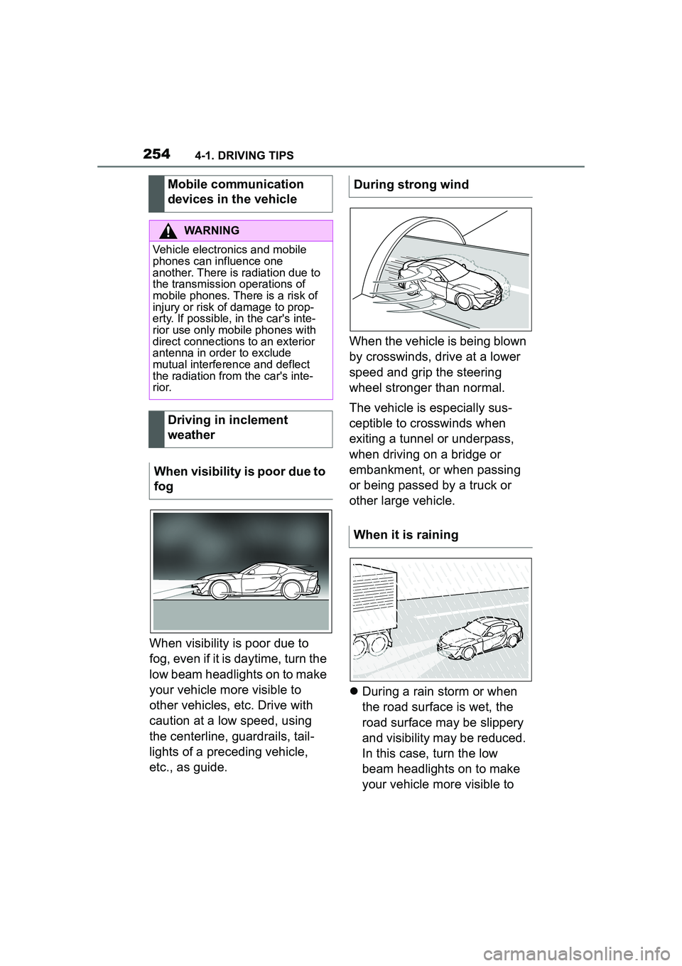
When visibility is poor due to
fog, even if it is daytime, turn the
low beam headlights on to make
your vehicle more visible to
other vehicles, etc. Drive with
caution at a low speed, using
the centerline, guardrails, tail-
lights of a preceding vehicle,
etc., as guide.When the vehicle is being blown
by crosswinds, drive at a lower
speed and grip the steering
wheel stronger than normal.
The vehicle is especially sus-
ceptible to crosswinds when
exiting a tunnel or underpass,
when driving on a bridge or
embankment, or when passing
or being passed by a truck or
other large vehicle.
During a rain storm or when
the road surface is wet, the
road surface may be slippery
and visibility may be reduced.
In this case, turn the low
beam headlights on to make
your vehicle more visible to
Mobile communication
devices in the vehicle
WARNING
Vehicle electronics and mobile
phones can influence one
another. There is radiation due to
the transmission operations of
mobile phones. There is a risk of
injury or risk of damage to prop-
erty. If possible, in the car's inte-
rior use only mobile phones with
direct connections to an exterior
antenna in order to exclude
mutual interference and deflect
the radiation from the car's inte-
r i o r.
Driving in inclement
weather
When visibility is poor due to
fog
During strong wind
When it is raining